Complete 2012.m version
Includes:
Instructions:
1. Download the file containing the installation of CYPE programs:
2. Decompress in any folder of the hard drive
3. Open the chosen language folder
4. Follow the installation instructions that appear on screen
- Improvements in the 2012.m version update patch (15th May 2012)
- Improvements in the 2012.l version update patch (24th April 2012)
- Improvements in the 2012.k version update patch (12th March 2012)
- Improvements in the 2012.j version update patch (21st February 2012)
- Improvements in the 2012.i version update patch (7th February 2012)
- Improvements in the 2012.h version update patch (26th December 2011)
- Improvements in the 2012.g version update patch (1st December 2011)
- Improvements in the 2012.f version update patch (21st November 2011)
- Improvements in the 2012.e version update patch (14th November 2011)
- Improvements in the 2012.d version update patch (10th October 2011)
- Improvements in the 2012.c version update patch (5th August 2011)
- Improvements in the 2012.b version update patch (23rd June 2011)
- Other versions
Improvements in the 2012.m version update patch (15th May 2012)
Code implementation and improvements in its application
Code regarding loads on structures. Wind loads
BS EN 1991-1-4:2005 (United Kingdom)
Eurocode 1: Actions on Structures. Part 1-4: General Actions – Wind actions. National Application Document for the United Kingdom.
Implemented in CYPECAD.
Code regarding loads on structures. Seismic loads
NSR-10 (Colombia); RPA 99/v 2003 (Algeria) and RPS 2011 (Morocco)
NSR-10 (Columbia): Reglamento Colombiano de Construcción Sismo Resistente (2010).
RPA 99/ 2003 (Algeria): Règles Parasismiques Algériennes RPA 99 / VERSION 2003.
RPS 2011 (Morocco): Règlement de Construction Parasismique (version revisée 2011).
These codes had already been implemented in previous versions of CYPECAD and Metal 3D with the dynamic analysis method (spectral modal), which each of them proposes.
The 2012.m version includes, for each of them:
- A static analysis method (equivalent lateral force)
The analysis method selection (dynamic or static) is carried out using the Analysis method option within the dialogue box where the seismic load is defined. - Correction due to base shear
This correction is applied to the seismic analysis when this is done using the dynamic analysis (spectral modal). More information on this topic can be found in the following section (Correction due to base shear).
Correction due to base shear for seismic design using dynamic analysis method
Certain seismic codes require for a minimum base shear to be met when the spectral-modal dynamic method is applied to analyse seismic loading. This check was already included in the 2012.l version for the SANS 10160-4:2011 (South Africa) code and the IS 1893 (Part 1): 2002 (India) code. The 2012.m version also includes this check for the NSR-10 (Columbia), RPA 99/v 2003 (Algeria) and RPS 2011 (Morocco) codes.
The value of the total dynamic shear at the base (Vd), obtained having carried out the modal combination (CQC), for any of the analysis directions, cannot be less than a specific limiting value. This value is equal to a percentage (α) of the shear at the base of the structure which has been analysed with the static method (Vs). In other words, the following condition must be met: ![]()
If the minimum base shear condition is not met, the results of the dynamic analysis must be adjusted by the following factor: ![]()
The adjustment covers all the results of the dynamic analysis, including the displacements, distortions, forces at the floors, floor shears, base shear and forces in the elements.
Export of corbels and piles to IFC format
In the 2012.k version, a new feature was implemented in CYPECAD whereby the majority of structural elements designed by the program could be exported to IFC format (Industry Foundation Classes). As of the 2012.m version, the exported elements list is completed by including corbels and piles.
Therefore, as of the 2012.m version, all the structural elements designed by CYPECAD can be exported to IFC format.
Please recall that the export to IFC is carried out using the Export to IFC format option (File > Export).
Budget adjustment for a bill of quantities with no job units
The 2012.m version of Arquimedes allows for the budget of a bill of quantities to be adjusted (by indicating the material execution budget value, the value of the contract execution budget or by indicating an adjustment coefficient), even though no job units have been introduced and only a chapter structure is present where the user has included the costs. In previous versions, the cost of a last level chapter could be introduced directly if it did not have any job units, but the adjustment of the budget did not act upon the costs of chapters without any job units.
Edition of box culvert reinforcement tables
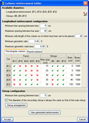
In previous versions of the Box Culverts program, the program contained internal reinforcement tables which could not be configured by users. The 2012.m version allows for these tables to be configured by indicating the admissible diameters and the spacing the reinforcement bars can have for each of the elements making up the culvert:
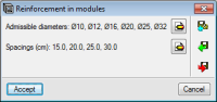
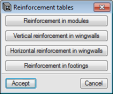
- Reinforcement in modules
- Vertical reinforcement in wingwalls
- Horizontal reinforcement in wingwalls
- Reinforcement in footings
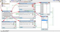
The admissible diameters and spacings between bars are defined in the Reinforcement tables dialogue box (Job > Reinforcement tables) using the ![]() button. The reinforcement configuration for each element can be saved in libraries and managed for other jobs using the following tools:
button. The reinforcement configuration for each element can be saved in libraries and managed for other jobs using the following tools:
 Export the reinforcement table configuration so to use it in other jobs.
 Import a reinforcement table configuration from those exported using the Export option.
 Select a reinforcement table configuration from those exported using the Export option, for it to be imported by default in new jobs.
Improvements in the 2012.l version update patch (24th April 2012)
- Code implementation and improvements in its application
- Concrete code
- Code regarding loads on structures. Wind loads
- Code regarding loads on structures. Seismic loads
- Improvements in the parallel analysis with 4 processors
Code implementation and improvements in its application
- ACI 318-11 (USA)
Building Code Requirements for Structural Concrete
Implemented in Embedded retaining walls, Reinforced concrete cantilever walls and Box culverts.
The ACI 318M-11 code (Metric Building Code Requirements for Structural Concrete) had already been implemented in previous versions for the same programs as for which the ACI 318-11 code has been implemented.
- IS 456: 2000 (India)
Plain and Reinforced Concrete - Code of Practice.
This code was already implemented in the 2011.h version in CYPECAD and Metal 3D. As of the 2012.l version, it has been implemented in Embedded retaining walls, Reinforced concrete cantilever walls and Box culverts.
Code regarding loads on structures. Wind loads
South African National Standard 10160-3:2011. Basis of structural design and actions for buildings and industrial structures. Part 3: Wind actions.
Implemented in CYPECADCode regarding loads on structures. Seismic loads
- SANS 10160-4: 2011 (South Africa)
South African National Standard 10160-4: 2011. Basis of structural design and actions for buildings and industrial structures. Part 4: Seismic actions and general requirements for building.
Implemented in CYPECAD and Metal 3D. Both Dynamic (spectral modal) and Static (equivalent lateral force) analysis methods have been implemented.
The correction due to base shear is included in this code. Certain seismic codes require for a minimum base shear to be met, when the spectral-modal dynamic method is applied to analyse seismic loading.
The value of the total dynamic shear at the base (Vd), obtained having carried out the modal combination (CQC), for any of the analysis directions, cannot be less than a specific limiting value. This value is equal to a percentage (α) of the shear at the base of the structure which has been analysed with the static method (Vs). In other words, the following condition must be met:

If the minimum base shear condition is not met, the results of the dynamic analysis must be adjusted by the following factor:

The adjustment covers all the results of the dynamic analysis, including the displacements, distortions, forces at the floors, floor shears, base shear and forces in the elements.
- IS 1893 (Part 1): 2002 (India)
Criteria for earthquake resistant design of structures. Part 1 General Provisions and Buildings.
This code was already implemented in CYPECAD and Metal 3D. As of the 2012.l version, the correction due to base shear is included in the same way as has been implemented for the SANS 10160-4: 2011 (South Africa) code.
Additionally, as of the 2012.l version, the analysis method (dynamic or static) is carried out using the Analysis method option from the dialogue box where the seismic loads are defined.
Centre of mass and centre of stiffness
Since the 2012.i version, CYPECAD provides an on-screen representation of the centre of mass and the centre of stiffness, if an analysis with static seismic loads is carried out. As of the 2012.l version, the centre of mass and the centre of stiffness are always represented on screen (regardless of whether the analysis has been carried out with static seismic loads, dynamic seismic loads, or no loads). Please recall that for these two points to be visible at each floor, the centre of mass and centre of stiffness reference (Groups > Show references) must be activated.
Additionally, as of the 2012.l version, when the job is analysed using the Indian static seismic code, IS 1893 (Part 1): 2002 (Section 7.5), the Justification of seismic action report, which is generated by the program (File > Print > Job report) includes the coordinates of the centres of mass and the centres of stiffness of all the floors. As of the 2012.l version, the centres of mass and centres of stiffness of each floor are included in this report for all the seismic codes used by the programs to analyse, regardless of whether the analysis is static or dynamic.
Therefore, as of the 2012.l version, each time the structure is analysed, the positions of the centre of mass and the centre of stiffness of each floor are obtained. To do so, the program needs to know the values of the Portion of live load to consider and the Portion of snow load to consider, which are used to determine the total mass of the building. These two values are indicated by the user in the dialogue box where the parameters defining the seismic action are defined. If the seismic analysis of the structure is not activated, these two values are specified using the new option: Centre of mass and centre of stiffness, located in the Analyse menu. This option is also available if seismic action is activated, but, in the dialogue which appears, only the portion of live load and snow load are indicated and coincides with that which has been introduced for the seismic action data (Job > General data > With seismic loading option > select corresponding seismic code).
Export of stairs to IFC format
As of the 2012.k version, CYPECAD allows for the export to IFC format (Industry Foundation Classes) of all the designed structural elements (except corbels and stairs). In the 2012.l version, the export to IFC of stairs has been implemented.
In CYPECAD, the export to IFC is carried out using the Export to IFC format (File > Export).
Improvements in the parallel analysis with 4 processors
The Parallel analysis with 4 processors module allow for the potential offered by computers with 4 multiprocessors to be used for CYPECAD, Metal 3D and the Dynamic fire simulation.
As of the 2012.l version, this module also allows for 6 or 8 processors to be used.
Improvements in the 2012.k version update patch (12th March 2012)
- Code implementation and improvements in its application
- Concrete code
- Code regarding loads on structures. Wind loads
- Code regarding loads on structures. Seismic loads
- CYPECAD
Code implementation and improvements in its application
- Eurocode 2 (France)
NF EN 1992-1-1 :2005/NA: Mars 2007
Implemented in CYPECAD and Metal 3D. Includes the National Application Document for France. By using this code in CYPECAD, Detailed Ultimate Limit State Check Reports can be generated for concrete columns and other tools, such as the new column editor and the automatic generation of column reinforcement tables, can be used.
More information on the codes included with these features and the use of these tools can be found in the Detailed Ultimate Limit State Check Reports of the new column editor section of the New features of CYPECAD. - NTC: 14-01-2008 (Italy)
Norme techniche per le construzioni
This code was already implemented in the 2012.i version in Metal 3D. As of the 2012.k version, it is also implemented in CYPECAD. Using this code in CYPECAD, Detailed Ultimate Limit State Check Reports can be generated for concrete columns and other tools, such as the new column editor and the automatic generation of column reinforcement tables, can be used.
More information on the codes included with these features and the use of these tools can be found in the Detailed Ultimate Limit State Check Reports of the new column editor section of the New features of CYPECAD. - EHE-08 (Spain)
Instrucción de hormigón estructural
This code was already implemented in all CYPE programs which design concrete elements (CYPECAD, Metal 3D, Soil retention elements and Box culverts) as of the 2009.1.e version.
In the 2012.k version, users have the possibility to choose whether or not CYPECAD is to consider the comments of Article 44.2.3.4.1. "Transverse reinforcement" of the EHE-08 code published by the "Ministerio de Fomento"
This comment indicates the following:
For beams within building elements with depths no greater than 30cm, the limit, according to the article, for the transverse spacing of the transverse reinforcement (St, trans) could oblige the user, in certain cases, to have to provide additional crossties which were not strictly necessary. In these cases, the spacing between transverse stirrups is acceptable if it complies with the following condition:
St, trans ≤ 2d < 350 mm
As it is a comment on the code, it is not obligatory and so it is up to the user's criteria whether or not to apply it. The 2012.k version of CYPECAD has this option activated by default for new jobs initiated with this version. For jobs coming from previous versions, the option is not activated by default, so that the results will continue to be the same as for that previous version. In any case, the user can activate or deactivate it by selecting the option Apply the condition of the comment within the Comments on article 44.2.3.4.1 of the EHE-08 code dialogue box (Job >General data > By position button > Beam options button > Comments on article 44.2.3.4.1 of the EHE-08 code). Please recall that to be able to activate this option, the EHE-08 code must be selected in CYPECAD. - ACI 318M-11 (USA - International)
Building Code Requirements for Structural Concrete.
This code was implemented in the 2012.i version in the Box Culverts program. As of the 2012.k version, it is also implemented for Reinforced concrete cantilever walls and Embedded retaining walls.
Code regarding loads on structures. Wind loads
- NSE2 (Guatemala)
Normas de Seguridad Estructural de edificaciones y obras de infraestructuras para la Republica de Guatemala.
Implemented in CYPECAD - RC80 (Costa Rica)
Reglamento de construcciones
Implemented in CYPECAD - REP-04 (Panama)
Reglamento para el diseño estructural en la República de Panamá
Implemented in CYPECAD
Code regarding loads on structures. Seismic loads
- NSR-10 (Colombia)
Reglamento Colombiano de Construcción Sismo Resistente (2010)
This code was implemented in the 2011.c version for CYPECAD and Metal 3D. In the 2011.k version, the specific analysis for the Seismic Microzoning of Bogota D.C. was implemented for both programs. Now, in the 2012.k version, the Seismic Microzoning of Cali has been implemented.
Article A.2.1.2.1 of the NSR-10 Regulation on Studies of Seismic Microzoning states: "When the municipal or district authorities have approved a seismic microzoning study, carried out in accordance with that stated in section A.2.9, which contains the recommendations for the site where the building will be built, be it using site effects of special spectral forms, these results must be used, as well as the site coefficient values, given in the regulation, instead of those shown in A.2.4 and A.2.6."
In the Code for the calculation of seismic loading dialogue box corresponding to the NSR-10 code (Job > General data > activate with seismic loading > select Colombia and NSR-10), where the option Cali has been implemented in the Seismic zone section for which any of its seismic microzones can be selected. Its selection has its corresponding design seismic spectrum definition. - NTC - 2008 (Italy)
Norme Tecniche per le Costruzioni (14 gennaio 2008) Paragrafo 3.2 Azione Sismica.
This code was already implemented in CYPECAD and Metal 3D as of the 2011.e version. In the 2012.j version, the seismic parameters corresponding to the location could be introduced (the program selects them automatically when the user introduces the coordinates or the city). Now, in the 2012.k version, as well as contemplating the seismic spectrum associated with a return period of 475 years for the analysis of the structure (since the NTC - 2008 code was implemented), the spectrum associated with a return period of 50 years is considered for the analysis of displacements due to seismic action.
CYPECAD allows for all the designed structural elements (except corbels and stairs) to be exported to IFC (Industry Foundation Classes) format. This way all the information which has been introduced and generated in CYPECAD can be read in CAD/BIM programs such as Allplan, Archicad, Revit Architecture etc.
To carry out the export, the option IFC (File > Export) has been implemented in CYPECAD.
Transverse spacing of transverse reinforcement (comments of Article 44.2.3.4.1 of the EHE-08 code)
The possibility of taking into account the comments of Article 44.2.3.4.1 of the EHE-08 code "Transverse reinforcement" published by the "Ministerio de Fomento" in the document "Modificaciones de los comentarios de los miembros de la Comisión permanente del Hormigón a la Instrucción de Hormigón estructural EHE 08 (Octubre 2010)". This comment refers to the transverse spacing of the transverse reinforcement in building elements with depths not exceeding 30 cm.
Improvements in the 2012.j version update patch (21st February 2012)
Code implementation and improvements in its application
Code regarding loads on structures. Wind loads
- CHOC-04 (Honduras)
Código Hondureño de la Construcción. Normas Técnicas Complementarias. XII. Cargas y Fuerzas Estructurales. Diseño por Viento.
Implemented in CYPECAD
Code regarding loads on structures. Seismic loads
- NTC - 2008 (Italy)
Norme Tecniche per le Construzioni (14 gennaio 2008) Paragrafo 3.2 Azione Sismica.
This code was already implemented in CYPECAD and Metal 3D in the 2011.e version. Now the seismic parameters describing the location can be introduced. The user can indicate the geographical coordinates or town to which the location belongs. The program then automatically introduces the corresponding seismic parameters (acceleration, amplification factor and initial period).
Assign soil data to foundation beams and mat foundations
The option, Assign soil data (Beam Definition tab > Beams/Walls) has been implemented which allows for the user to define the subgrade modulus and allowable bearing pressure of the soil below the foundation beams and mat foundations that have been introduced, without having to edit these foundation elements.
Upon selecting this option, the Assign soil data dialogue box opens. Within it, the properties of the soil can be introduced, so they can then be assigned to foundation beams and mat foundations in one three different ways:
- Assign button
This option closes the dialogue box and assigns the introduced soil data to the foundation beams and mat foundations which are subsequently selected using the left mouse button, by clicking on them one by one or using a capture window. - Assign all button
This option closes the dialogue box and assigns the introduced soil data to all the foundation beams and mat foundations that have been introduced on the current floor. - Copy from button
This option closes the dialogue box and allows for the user to copy the soil data of the foundation beam or mat foundation which is selected using the left mouse button. Upon doing so, a new dialogue box Assign soil data appears containing the data of the selected foundation beam or mat foundation. This data can now be assigned to other foundation beams or mat foundations using the Assign or Assign all buttons.
The Assign soil data option (Beam Definition tab > Beams/Walls) will appear deactivated if no foundation beams or mat foundations have been introduced in the current floor.
The option Assign data to corbels (Beam Definition tab > Beams/Walls > Corbels) has been implemented in the program. This option opens a new dialogue box where the materials, geometry and reinforcement of a corbel can be defined, so to then assign these properties (using the Assign button) to any corbels which have been introduced.
The corbel properties indicated in this dialogue box can also be copied from other corbels using the Copy from button.
Checks for reinforced concrete columns with sections smaller than 19 cm in accordance with the NBR 6118:2007 (Brazil) code
Implemented in this update patch are the checks specified by the Brazilian NBR 6118:2007 code, specific for reinforced concrete columns with a section in which one of the dimensions lies between 19 cm and 12 cm. These checks appear in the ultimate limit state check reports of concrete columns. In previous versions, the program would indicate that these columns failed.
Change text into capital/small case letters
Three new options have been implemented which allow users to change uppercase letters to lowercase letters in the description, summary or notes texts of the concept which has been selected in the Decomposition tree.
These options are represented by three buttons in the toolbar located in the summary field (bottom part of the screen) and appear upon selecting a cell in the Summary column of the Decomposition tree window.
These buttons are as follows:
 Changes the selected text into uppercase letters.
 Changes the selected text into lowercase letters.
 Modifies the selected text and changes the first letter of each sentence into an uppercase letter and leaves the remaining letters in lowercase.
For all three cases, if no text has been selected, the modification shall be applied to all the contents of the window in which the cursor is located (complete concept description, summary and notes windows). If the cursor is not situated in any of the aforementioned texts, the modification shall be applied to the complete description of the concept.
Improvements in the 2012.i version update patch (7th February 2012)
- Code implementation and improvements in its application
- CYPECAD
- Arquimedes and Job control
Code implementation and improvements in its application
- NTC: 14-01-2008 (Italy)
Norme tecniche per le construzioni
Implemented in Metal 3D - ACI 318M-11 (USA – International)
Building Code Requirements for Structural Concrete
Implemented in Box Culverts - ACI 318M-08 (USA – International), CIRSOC 201:2005 (Argentina), NCH430.OF2008 (Cile) and NTE E.060:2009 (Peru)
- The following new features have been implemented in CYPECAD for concrete codes ACI 318M-08 (USA – International), CIRSOC 201:2005 (Argentina), NCH430.OF2008 (Cile) and NTE E.060:2009 (Peru):
- Detailed Ultimate Limit State reports for concrete columns in CYPECAD’s new column editor
- CYPECAD’s new column editor
- Automatic generation of column reinforcement tables
These tools were already available in CYPECAD for the following concrete codes:
- EHE-08 (Spain) [as of the 2012.c version]
- Eurocode 2 (EU International) [as of the 2012.d version]
- Eurocode 2 (Portugal) [as of the 2012.d version]
- IS 456: 2000 (India) [as of the 2012.e version]
- NBR 6118:2007 (Brazil) [as of the 2012.e version]
More information on the Detailed reports on the Ultimate Limit State checks of concrete columns in CYPECAD's new column editor can be found by clicking on the link.
Code regarding loads on structures. Wind loads
- Grouping of wind codes by country
In the wind code selection dialogue boxes in CYPECAD and Portal Frame Generator, the user first of all selects the country and to the right of the dialogue box selects the wind code of the country with which the job is to be analysed, for those countries with more than one wind code available in the program. In previous versions, all the wind codes were listed, with a description of the country of each code. This grouping was carried out in a similar manner for seismic codes in the 2010.h version. - ASCE/SEI 7-10 (USA – International)
Minimum Design Loads for Buildings and Other Structures
Implemented in CYPECAD - NCh432.Of71 (Chile)
Cálculo de la acción del viento sobre las construcciones
Implemented in CYPECAD
Code regarding loads on structures. Seismic loads
- IS 1893 (Part 1): 2002 (Section 7.5) (India)
Criteria for earthquake resistant design of structures. Part 1 General Provisions and Buildings (Section 7.5)
Implemented in CYPECAD. The dynamic seismic analysis in accordance with this code was implemented in the 2010.m version. As of the 2012.i version, the static seismic analysis in accordance with section 7.5 of the code has been implemented. Therefore, as of the 2012.i version, users can choose whether to carry out a static or dynamic analysis using this code. - NCh433.OF1996 Mod.2009 (Dºnº61. De 2011) (Chile)
Norma Chilena Oficial. Diseño Sísmico de Edificios. Includes modifications of the Decreto nº 61 (V. y U.) de 2011
Implemented in CYPECAD and Metal 3D - Eccentricity of seismic action with static seismic loading defined using coefficients per floor.
Seismic load eccentricity can now be defined at each floor when defining the static seismic load acting on a structure using the coefficients per floor option.
Positive and negative eccentricities for seismic action can be defined along the X-axis or Y-axis of each floor.
Static seismic analysis in CYPECAD jobs with integrated 3D structures
Before the 2012.i version, CYPECAD structures which included an integrated 3D structure could not be analysed with static seismic loading, as the bars of these structures were not grouped by floor. As of the 2012.i version, the program has a new option: Assign floors (Integrated 3D structure edition window > Bar > Assign floors), which for a static seismic analysis, allows the user to assign the bars to floors that have been created in CYPECAD. The floors can be assigned automatically or manually:
- Automatic assignment
The program automatically assigns all the bars of the integrated 3D structure which is being edited to the floors that have been created in CYPECAD. If a bar coincides approximately with one of the floors defined in CYPECAD, the program will assign the bar to that floor. If the bar is situated approximately between two floors, the program will assign the bar to both floors, in such a way that the mass of the bar will be divided between both floors for the static seismic analysis. Any bars which have been assigned automatically can then be modified using the Manual assignment option.
After selecting the option, the user has two ways of seeing to which floor each bar has been assigned:- By placing the mouse on a bar
A information window will appear providing information on the bar and its Location (floor to which the bar has been assigned). - By carrying out a zoom until the description of the bar can be seen
In this case, the floor or floors to which the bar has been assigned can be seen as well as its description.
- By placing the mouse on a bar
- Manual assignment
In this case, the user decides to which floor, defined in CYPECAD, the bars of the integrated 3D structure are to be assigned. Having selected this option, one or several bars can be selected by clicking on them using the left mouse button, or by opening a capture window, or combining both bar selection methods. Once the selection has been carried out, by clicking on the right mouse button, the user can choose to which floor the selected bars are to be assigned or between which two floors the bar is located.
The user can see to which floor each bar has been assigned to, in the same way as for the Automatic assignment.
The Assign floors option is only available if a code with static seismic analysis has been selected in CYPECAD. For the 2012.i version, the codes are:
- IS 1893 (Part 1): 2002 (Section 7.5) (India)
Bear in mind that a dynamic seismic analysis (IS 1893 (Part 1): 2002) or a static seismic analysis (IS 1893 (Part 1): 2002 (Section 7.5)) can be carried out with this code. - Analysis using coefficient per floor
Located within the International code group
Representation of the centre of mass and centre of stiffness at each floor with the static seismic analysis
If a static seismic analysis is carried out, CYPECAD represents the centre of mass and the centre of stiffness on screen. To do so, the Centre of mass and centre of stiffness reference must be activated (Groups > Show references). The static seismic analysis codes included in the 2012.i version can be consulted in the previous section.
When the job is analysed using the IS 1893 (Part 1): 2002 (Section 7.5) (India) static seismic code, within the seismic action justification report generated by the program (File > Print > Job report), the coordinates of the centre of mass and centre of stiffness of all the floors are included.
Improvements in the Column schedule and Column detailing
Users can now configure the size of the texts and thickness of the lines represented in the Column schedule and Column detailing drawings (File > Print > Job drawings > Add a drawing > Select the type of drawing (Detailing of columns or column schedule > Pen thickness and text button)
Within the Detailing of columns drawing, the horizontal scale (cross-section) and vertical scale (elevation) do not have to be the same. Additionally, further options have been implemented in the Detailing of columns drawings: Detailing of each column and Detailing of columns in plan.
Improved export and import of Accounts and Purchase groups in Job control
Within the dialogue boxes which open using the Export accounts and Import accounts menu options (Job control > Accounts) users can export or import depending on a specific accounts file. This option is useful to export or import supplier accounts, client accounts, etc. of a specific geographical area.
Within the Purchase groups dialogue box (Job control > Purchase management > Purchase groups), two new buttons have been implemented: Export purchase groups and Import purchase groups. As occurs with the export and import account options, these options are useful for exporting and importing purchase groups of a specific geographical area.
Improved offer reception for purchase management
Within the Offer reception dialogue box (Job control > Purchase management > Offer reception), a Paste button has been implemented which copies the contents of the Windows clipboard to the offer reception table of the selected supplier. So the data of the clipboard can be used in Arquimedes, a table of the document which has been sent by the supplier must first have been copied to the clipboard. This table can be copied with any file format in which the supplier sends the offers (spreadsheet, text processor, PDF...). The procedure to follow is indicated below:
- Open the document which has been received from the supplier. The information Arquimedes requires from this document are the offer prices of the supplier and their code.
- Select the table or part of the table containing the prices to be pasted to Arquimedes, in such a way that the first column of the selected table contains the concept codes and the last contains the price of each concept. This way, Arquimedes can identify to which concept each price corresponds to. Only the concept prices which are identified by their code will be taken.
Another option is to only select the price column. In this case, please ensure that the order of the prices coincides with the contents of the list. - Copy the selected data to the clipboard, return to Arquimedes and press the Paste button to import the received prices.
Improved purchase comparative management
The Purchase comparatives dialogue box has been improved (Job control > Purchase management > Purchase comparatives) and now displays the selected supply totals by supplier and future contract.
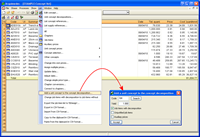
Change concept codes in the file to export to FIEBDC-3
Within the Export to FIEBDC-3 dialogue box (File > Export > Export to FIEBDC-3), a new option has been included: Change concept codes in the export file, which allows for the concept codes of the database which is going to be generated in the export, to be modified. This is useful for users which have to redo all the codes of the chapters and job items so to adapt them to the presentation requirements of the project or to adapt them to an internal code system of a company.
Reduction of the concept code characters in the file to export to FIEBDC-3
As of previous program versions, users have been able to reduce the number of characters of the codes of the chapters of a database when they are exported to FIEBDC-3 format. To do so, an option was implemented: Reduce codes with more than 13 characters (File > Export > Export to FIEBDC-3 > Accept the dialogue box > Export to FIEBDC-3 dialogue box > Compatibility with Presto section). This allows Presto (which limited the number of concept characters to 13) to interpret correctly, the codes of the BC3format file generated by Arquimedes when there are codes containing more than thirteen characters. More recent versions of Presto increased the maximum number of allowable characters. There are other tools which also limit the maximum number of characters with different values.
For this reason, as of the 2012.i version, the option Reduce codes with more than 13 characters can be configured and users can choose the maximum number of characters which the concepts that are going to be exported to FIEBDC-3 can contain. This way, concepts which have a greater number than that indicated will be reduced by Arquimedes in the resulting FIEBDC-3 export file and so will be interpreted correctly by other applications which limit the number of characters of the concept when reading FIEBDC-3 formats.
Improvements in the 2012.h version update patch (26th December 2011)
- Plane stress walls (new CYPECAD module)
- Code implementation and improvements in its application
- CYPECAD
Plane stress walls (new CYPECAD module)
CYPECAD’s new module: Plane stress walls, designs reduced thickness reinforced concrete walls with a single reinforcement plane, which are used as load bearing walls to support vertical loads and also resist horizontal forces acting in the plane of the wall. They are commonly used in some countries: Columbia, Ecuador, India or Peru.
More information on this module can be found at the Plane stress walls webpage.
Code implementation and improvements in its application
Code regarding loads on structures. Wind loads
- COVENIN 2003-89 (Venezuela)
Acciones del viento sobre construcciones.
Implemented in CYPECAD and Portal frame generator - NC 285: 2003 (Cuba)
Carga de viento. Método de cálculo.
This code is already implemented in CYPECAD as of the 2010.e version. As of the 2012.h version, it is also implemented in the Portal frame generator.
Code regarding loads on structures. Seismic loads
- 2011 PRBC (Puerto Rico)
2011 Puerto Rico Building Code. Section: 1613 Earthquake Loads.
Implemented in CYPECAD and Metal 3D.
- Bill of quantities of the structure designed in CYPECAD for the French version
The French version of CYPECAD generates and exports the bill of quantities of the designed structure to Arquimedes. - Assign foundations to walls
The option, Assign foundations, has been implemented in the Assign walls dialogue (Beams/Walls > Assign walls). This option assigns foundations to a previously introduced wall without the need of having to edit it.
Improvements in the 2012.g version update patch (1st December 2011)
- Code implementation
- CYPECAD and Metal 3D. Joints
- Arquimedes
- ANSI/AISC 360-10 (LRFD) (USA – International)
Specification for Structural Steel Buildings.
This code was implemented in the 2012.e version for the design of rolled and welded steel sections in CYPECAD, Metal 3D and the Portal Frame Generator. As of the 2012.g version, the code has been implemented in the five joints modules (Joints I, Joints II, Joints III, Joints IV and Joints V). - NTC: 14-01-2008 (Italy)
Norme tecniche per le construzioni (14 gennaio 2008).
This code was implemented in the 2011.h version for the design of rolled and welded steel sections in CYPECAD, Metal 3D and the Portal Frame Generator. As of the 2012.g version, the code has been implemented in the five joints modules (Joints I, Joints II, Joints III, Joints IV and Joints V).
Code regarding loads on structures. Seismic loads
- PS-92 (version révisée 2010) France
Règles de Construction Parasismique
Règles PS applicables aux batiments – PS 92 (version révisée 2010)
Code implemented in CYPECAD and Metal 3D
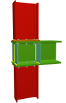
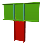
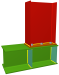
Column-beam connections with continuous beam at the node


New types of column-beam connections have been implemented in the Joints I, Joints II, Joints III and Joints IV modules, in which the beam is continuous at the node and the column is interrupted.
- For Joints I, Joints II, Joints III and Joints IV
- Column below continuous beam
- Column above continuous beam
- For Joints III and Joints IV (as well as the types stated above)


- Column above and below continuous beam
The nodes must have the following properties so they can be resolved with the new types of continuous beam joints:
- Coplanar webs
The webs of the columns and beam must be coplanar. - Without any perpendicular sections
The joint is not designed if there are sections reaching the node perpendicularly to the plane defined by the columns and the beam. - Slope of the beam
The beam can be inclined. - Fixity of the columns to the beam
For the Joints II and Joints IV (bolted) modules, columns must be fixed (moment connection) to the beam, whereas in the case of the Joints I and Joints III (welded) modules, the columns can be fixed or simply connected to the beam. - Flange width of the beam with fixed column
- At end frame nodes
The width of the flange, for columns situated at the end frame nodes, has to be greater than the flange of the column. - At intermediate frame nodes
For columns situated at intermediate frame nodes (with continuous beam at the node), the width of the flange of the beam must be greater than or equal to the width of the flange of the column.
- At end frame nodes
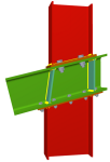
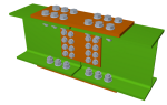
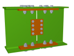
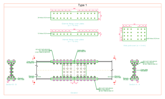
Splice connection with bolted cover plates
Splice connections of two sections using bolted cover plates have been implemented in the Joints II and Joints IV (bolted) modules. They can be designed in accordance with any of the codes used by these modules (implemented codes for Joints II and implemented codes for Joints IV).
The nodes must have the following properties so the splice connection can be resolved with bolted cover plates:
- Coplanar webs and parallel axes
Both sections must have coplanar webs and parallel axes. - Section depths and packs
The sections do not have to have the same depth or their axes aligned. The program uses packs if they are required, as long as the required thickness for a pack is greater than or equal to 2mm. Otherwise a gap is left. - Column connections
The program tries to design the splice connections between columns using cover plates. If this is not possible, it will design them using front plates (if the column sections are the same). - Non-vertical section connections
The design sequence is the opposite to the columns’ design sequence. In other words, the program tries to design the splice connection of the two sections using front plates (if the sections are the same). If it is not possible, it tries to design them using cover plates. - Cover plate design
Web cover plates are designed to resist the shear acting perpendicular to the axes of the sections, whereas the flange cover plates are designed to support the remaining five forces.
- Cover plate layout
- Sections with the same internal depth
Initially, the program only provides internal cover plates at the flanges. If it fails, external cover plates are added. - Sections with different internal depth
Initially, the program provides an external cover plate. If it fails, internal cover plates are added.
- Sections with the same internal depth
 Connection stiffness
Section splice connections resolved using cover plates are considered rigid, hence the rotational stiffness at the ends of both sections need not be defined.
More code implementations for joint design
The codes indicated below were implemented in a previous version for the design of rolled and welded steel sections in CYPECAD, Metal 3D and the Portal Frame Generator. As of the 2012.g version, the code has been implemented for the design of welded and bolted connections in the five joints modules (Joints I, Joints II, Joints III, Joints IV and Joints V).
- ANSI/AISC 360-10 (LRFD) (USA – International)
Specification for Structural Steel Buildings - NTC: 14-01-2008 (Italy)
Norme tecniche per le construzioni (14 gennaio 2008).
Add a unit item to the concept decomposition of a price bank
The option Add a unit concept to the concept decomposition for price banks has been implemented in the program (Concept list > Show > Concept list). This option was already available in previous versions for bills of quantities.
In a price bank, this option opens the Add a unit concept to the concept decomposition dialogue box, in which the user selects the types of concepts with decomposition (job items with decomposition and unjustified job items) to which a unit item selected from the same dialogue can be added. This unit item will be included in the decomposition of concepts present in the Concept list window which are of the selected type or types.
This option is useful for adding the same unit concept to a group of decomposed prices or unclassified simple prices in a price bank.
Add indirect expenses to a price bank when exported in HTML format
As of previous versions, it is possible to export a price bank in HTML format, so to publish it as a web-page (File > Export > Publish price bank in HTML format). In the 2012.g version, this export can be carried out including the indirect expenses of a specific chapter. The indirect expenses percentage and the chapter to which it is applied are indicated in the Publish price bank in HTML format dialogue box which appears when the option mentioned in File > Export.
Connection with Allplan 2012 (32-bits)
Arquimedes has been updated to adapt to the changes introduced in the 2012 (32-bit) version of Allplan so to maintain the connection between both applications.
Connection with ArchiCAD 15 (32-bits)
Arquimedes has been updated to adapt to the changes introduced in ArchiCAD 15 (32-bit) so to maintain the connection between both applications.
Improvements in the 2012.f version update patch (21st November 2011)
CYPE’s Project Management program is now available to our users in English. Create, manage and control bills of quantities, project certifications and specifications with this highly versatile tool.

For more information on Arquimedes and its features please click here.
Code regarding loads on structures. Seismic loads
- 2009 IBC (USA International): International Building Code
Code implemented in CYPECAD and Metal 3D - RPS 2011 (Morocco): Règlement de Construction Parasismique (version révisée 2011)
Code implemented in CYPECAD and Metal 3D
Improvements have been included for when generating the Column schedule drawing obtained once the job has been analysed using codes which provide users with detailed ultimate limit state reports. These improvements are detailed below:
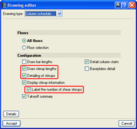
Improvements in the configuration options of the Column schedule drawing
The following options have been implemented, providing the user with further configuration options for the Column schedule drawing of the job:
- Draw stirrup lengths
- Detailing of stirrups
- Label the number of shear stirrups
Improvements in layer organisation of the Column schedule drawing
Improvements have been implemented in the organisation of the layers used in the Column schedule drawing:
- The longitudinal reinforcement and transverse reinforcement belong to different layers.
- The labels of the longitudinal reinforcement and labels of the transverse reinforcement belong to different layers.
- The text and lines of the Column schedule and the text and lines of the table containing the reinforcement data belong to different layers.
- Concrete column sections and steel column sections belong to different layers.
- Dimension text of the column transverse sections and their corresponding lines belong to different layers.
Improvements in the 2012.e version update patch (14th November 2011)
Code implementation and improvements in its application
- IS 456:2000 (India) and NBR 6118:2007 (Brazil)
The following features have been implemented for IS 456:2000 (India) and NBR 6118:2007 (Brazil): - Detailed Ultimate Limit State reports for concrete columns in CYPECAD’s new column editor
- New column editor of CYPECAD
- Automatic generation of column reinforcement tables
CYPECAD's new column editor offers extensive and thorough information on the data, checks, details and results of all the reinforced concrete and steel columns of the job, including detailed Ultimate Limit State (U.L.S.) reports. The U.L.S. reports allow the user to verify, justify and optimise column design in CYPECAD.
These tools were already available in CYPECAD, as of the 2012.c version, for the EHE-08 code (Spain) and as of the 2012.d version for Eurocode 2 (International and Portugal).
More information on this tool can be found at the Detailed reports on the Ultimate Limit State checks of concrete columns in CYPECAD’s new column editor in the New Features section.
- ANSI/AISC 360-10 (LRFD) (USA – International): Specification for Structural Steel Buildings.
Code implemented in CYPECAD, Metal 3D and Portal frame generator for the design of rolled and welded steel using the ultimate limit state method (load and resistance factor design).
Code regarding loads on structures. Seismic loads
- COVENIN 1756-1:2001 (Venezuela): Norma Venezolana COVENIN 1756-1:2001. Edificaciones sismorresistentes.
Implemented in CYPECAD and Metal 3D.
Improvements in the 2012.d version update patch (10th October 2011)
Code implementation and improvements in its application
- Eurocode 2 (EU International) and Eurocode 2 (Portugal)
The following features have been implemented for Eurocode 2 (EU International and Portugal):
- Detailed Ultimate Limit State reports for concrete columns in CYPECAD’s new column editor
- New column editor of CYPECAD
- Automatic generation of column reinforcement tables
CYPECAD's new column editor offers extensive and thorough information on the data, checks, details and results of all the reinforced concrete and steel columns of the job, including detailed Ultimate Limit State (U.L.S.) reports. The U.L.S. reports allow the user to verify, justify and optimise column design in CYPECAD.
These tools were already available in CYPECAD, as of the 2012.c version, for the EHE-08 code (Spain).
More information on this tool can be found at the Detailed reports on the Ultimate Limit State checks of concrete columns in CYPECAD’s new column editor in the New Features section.
Code regarding loads on structures. Seismic loads
- CHOC-04 (Honduras): Código Hondureño de la Construcción. Normas Técnicas Complementarias. XII. Cargas y Fuerzas Estructurales. Diseño por Sismo.
New as of the 2012.d version is the possibility of uninstalling CYPE programs using the Add or Remove Programs tool of Windows. The way in which the tool is executed depends on the Windows operating system in use:
- Windows XP, 2000 and 2003 Server
Windows Start button > Control Panel > Add or Remove Programs > Find the program in the list and select it using the left mouse button > select the “Add or Remove” button of the program to uninstall. - Windows Vista, 2008 Server and 7
Windows Start button > Control Panel > Programs and Features > Find the program in the list > click on the program to uninstall with the right mouse button and select the Uninstall option.
With this tool, Windows will delete the following directories or elements from the drive where CYPE programs have been installed:
- Any shortcut to CYPE programs (Desktop or Programs Menu) that was created automatically by the CYPE program installation assistant. If the user modifies the location or name of this shortcut, it will not be deleted.
- The subfolder “Version …” (corresponding to the version which has been selected to uninstall) within the “CYPE Ingenieros” folder.
- The “usr” folder, if the user selects the option to also delete all CYPE program configuration files. This option is deactivated, by default, when the user selects to uninstall the program from the Windows tool. It is recommended the “usr” folder not be deleted if other CYPE program versions are installed in the same drive. Deleting the “usr” folder will cause the loss of any user-configured program options (reinforcement tables, user-defined sections…).
The subfolders contained within “CYPE Ingenieros” will never be deleted (except for the Version … subfolder), as it is within these folders that CYPE saves all its jobs and drawings. If the user wishes to delete these subfolders, it will have to be done manually and care must be taken to ensure that safety copies have been made of all the data which is to be saved.
Improvements in the 2012.c version update patch (5th August 2011)
- Rolled, welded and cold-formed steel codes
- Code regarding loads on structures. Seismic loads
Improvements in code application
- Rolled and welded steel code
- IS 800:2007 (India)
General Construction in Steel – Code of Practice
This code was already implemented in previous versions for the design of simple rolled and welded steel sections in CYPECAD, Metal 3D, the Portal Frame Generator and the five Joints modules (Joints I, Joints II, Joints III, Joints IV and Joints V). Now, in the 2012.c version, the design of composite sections has been implemented. - Cold-formed steel code
- ABNT NBR 14762:2010 (Brazil)
Dimensionamento de estruturas de aço constituídas por perfis formados a frio.
This code was implemented in the previous update patch (2012.b) for CYPECAD, Metal 3D and the Portal Frame Generator. Now, in the 2012.c version, a check on buckling due to distortion for cold-formed steel sections has been implemented within the ultimate limit state (U.L.S.) checks.
Detailed ultimate limit state check reports for concrete columns with CYPECAD's new column editor
The 2012.c version of CYPECAD incorporates a new column editor which displays all the information regarding their design including the generation of detailed ultimate limit state (U.L.S.) check reports. This new tool is available when the job is analysed using the Spanish EHE-08 concrete code and will be implemented for other concrete codes in upcoming versions.
CYPECAD, Metal 3D and the Portal Frame Generator already provide detailed U.L.S. check reports for rolled, welded and cold-formed steel, aluminium and timber.
Now, with the 2012.c version, CYPECAD provides detailed ultimate limit state (U.L.S.) check reports for concrete columns. These reports contain all the checks carried out by the program to design reinforced concrete columns. Hence, these constitute an important document with which the user can verify and justify the design of the concrete columns and optimise their design. The level of detail of these reports also informs the user of all the checks a concrete column is submitted to. The program does not just simply indicate whether the column passes or fails all the checks, it also indicates which specific checks it fails. Additionally, each check is accompanied by the code and article to which the check refers to.
More information on the detailed ultimate limit state check reports for concrete columns can be found in the Detailed ultimate limit state check reports for concrete columns with CYPECAD’s new column editor section of the New features of the 2012 version in CYPECAD page.
Automatic generation of column reinforcement tables
New to CYPECAD for the 2012.c version, as well as the new column editor and the detailed ultimate limit state check reports, is the automatic generation of column reinforcement tables for jobs analysed using the Spanish EHE-08 concrete code and will be implemented for other concrete codes in upcoming versions.
The automatic generation is a wonderful new feature for users who wish to use personalised column reinforcement tables, which will save them time and effort by them not having to undertake the usual laborious tasks, and with complete guarantee that the reinforcement table generated by CYPECAD is coherent and fulfils their expectations. Additionally, users who in previous versions rejected the idea of creating their own column reinforcement tables due to the complexity of the process, can now personalise them easily.
More information on the automatic generation of column reinforcement tables can be found in the Automatic generation of column reinforcement tables section of the New features of the 2012 version in CYPECAD page.
Justification of seismic action report
A new report has been implemented in CYPECAD and Metal 3D justifying the values used for the analysis of seismic loads. This substitutes the Participation coefficients report of previous versions and is referred to as the Justification of seismic action report (in CYPECAD: File> Print > Reports, and in Metal 3D: Analysis > Dynamic seismic loading).
In previous versions, the Participation coefficients report displayed the summarised results of the seismic analysis carried out by the program.
As of the 2012.c version, the Justification of seismic action report of CYPECAD and Metal 3D provides the following information:
- Seismic general data
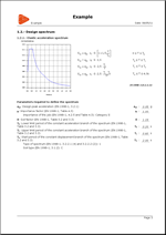
- Analysis spectrum
This displays: - The detailed development of the elastic and design spectrums used internally by the program for the analysis
- The values of the parameters required to define these spectrums
- The formulae and representation of the parameters defining the spectrums
- Reference to the seismic articles used.
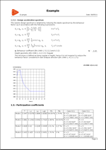
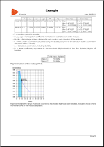
- Participation coefficients
This displays: - The participation coefficients table
The results displayed are justified with the data exposed in the previous section, as they establish how the design spectral accelerations are obtained based on the spectrums that have been defined, by substituting the modal periods that have been calculated. - Modal period representation
An image is attached displaying the range of periods covered by the modes that have been studied, indicating those where more than 30% of the mass is displaced.
Collective protection systems. New tools
New tools have been created and some of the existing options have been improved for the provision of vertical safety nets and guardrails, and for limiting stacking zones (Health and Safety tab):
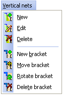
- Vertical nets
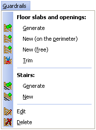
New options have been implemented: New bracket, Move bracket, Rotate bracket and Delete bracket in the Vertical nets menu. Using these tools, the brackets of the safety nets that have been generated can be added, moved, rotated and deleted. - Guardrails
The New option within the Guardrails menu now has two further options: - New (on the perimeter)
This option works in the same way as it did previously (places guardrails on the perimeters and openings indicated by the user). - New (free)
The program already generated guardrails at elevations changes between floor slabs represented in CYPECAD, but could not detect this change if it was not defined using structural elements. Now, using this option, guardrails can be provided at any position. - Stacking zones
Within the Stacking zones menu, the Trim option has been improved and the Move text option has been implemented: - Trim
Allows for the user to draw a closed polygonal outline so that the area of the stacking zone lying within it is deleted. In previous versions, this option only allowed the user to define a straight line to divide a stacking zone and delete the smallest of the two areas. - Move text
Allows for the user to move the text box in the stacking zone.
Improvements in the 2012.b version update patch (23rd June 2011)
This version revision contains improvements on the new Export to XML ADENE format module of the Portuguese version of the Building Services programs and the implementation of international codes and improvements in its application.
- Concrete code
- ABNT NBR 6118:2007 (Brazil)
Projeto de estruturas de concreto – Procedimento
Implemented in CYPECAD and Metal 3D. - CBH 87 (Bolivia)
ICS 91.080.40 Estructuras de hormigón. Año 1987
Implemented in CYPECAD and Metal 3D. - Eurocode 2 EN 1992-1-1
The following codes have been implemented in the Embedded Retaining Walls program:- Eurocode 2 (UE – International). General document.
- Eurocode 2 (Bulgaria). Document adapted to Bulgaria.
- Eurocode 2 (Romania). Document adapted to Romania.
- Eurocode 2 (Portugal). Document adapted to Portugal.
- NCh430.Of2008 (Chile)
Hormigón armado – Requisitos de diseño y cálculo
Implemented in CYPECAD and Metal 3D. - NTCRC:2004 (Mexico)
Normas técnicas complementarias para diseño y construcción de estructuras de concreto para el Distrto Federal
Implemented in CYPECAD and Metal 3D. - NTE E.060:2009 (Peru)
Concreto armado
Implemented in CYPECAD and Metal 3D. - Rolled and welded steel code
- ABNT NBR 8800:2008
Projeto de estruturas de aço e de estruturas mistas de aço e concreto de edificios
As of the 2012.b version, Composite sections have been included for this Brazilian code. The ABNT NBR 8800:2008 code was implemented in previous versions for the design of welded and bolted connections resolved by the Joints I, Joints II, Joints III, Joints IV and Joints V modules, and for the design of rolled and welded simple steel sections in CYPECAD and Metal 3D. - Cold formed steel code
- ABNT NBR 14762:2010 (Brazil)
Dimensionamento de estruturas de aço constituídas por perfis formados a frio.
This Brazilian code has been implemented for cold formed steel sections. The sections which can be used are the same as those available with the NBR 14762:2001 code, which is currently no longer in force. Both codes are implemented in CYPECAD, Metal 3D and the Portal Frame Generator. - Code regarding loads on structures. Wind loads
- E.020 Technical Code (Peru)
Norma técnica de edificación E.020 cargas – Apartado 5. Cargas debidas al viento.
Section 5 of the E.020 technical building code of Peru regarding wind loads has been implemented in the Portal Frame Generator. This code was already implemented in previous versions of CYPECAD. - Code regarding loads on structures. Seismic loads
- ABNT NBR 15421:2006 (Brazil)
Projeto de estruturas resistentes a sismos – Procedimento
Implemented in CYPECAD and Metal 3D - R-001 2011 (Dominican Republic)
Reglamento para el Análisis y Diseño Sísmico de Estructuras
Implemented in CYPECAD and Metal 3D.
Metal 3D now allows for structural analysis models to be imported from IFC files. IFC files which only contain the physical model and not the structural analysis model, do not contain any information which Metal 3D can read.
In IFC format files, the structural analysis model is composed of structural type entities, such as nodes, bars, loads, etc. Additionally, the relationship between nodes and bars is defined in an explicit way by means of fixity conditions. It is similar to the model a user would define in Metal 3D.
The entities Metal 3D currently imports from the IFC files are the following:
- Nodes (IFCStructuralPointConnection), with its external fixity conditions.
- Bars (IFCStructuralCurveMember), with its end fixity conditions and their descriptions.
These basic features regarding the import of IFC files do not require any special permits in the user license, hence any user whose license includes the 2012 version of Metal 3D will be able to import IFC files with the indicated properties.
Metal 3D carries out the import of IFC files into a new job with the aid of a data introduction assistant. When a new job is created (File > New) the program allows to choose between two options:
- New job
This is the default option that was executed when a new job was created in previous versions. Upon choosing it, the data introduction assistant of Metal 3D opens so the general data of the job can be defined. - Automatic introduction IFC
This option is used to import the structural analysis models from IFC files. Upon selecting it, the same assistant as in the previous option (New job) opens but with two additional steps: - IFC file selection
In this step the user can select: - The IFC file where the information to import is located
- The view of the IFC file to be imported
This option will be available if the IFC file has different views available. The IFC format allows for different groups of structural elements to be defined within the same file, with the aim to be able to analyse specific zones of the structure without the need of having to create a new file containing only that region of interest. For example, the IFC file containing the structure of a warehouse and an intermediate floor slab could contain two views, on with only the intermediate floor and the other with all the elements. - Section library
This step of the program displays the Library selection dialogue box of Metal 3D. Within this dialogue box, the sections each library contains can be visualised, new libraries can be created and the default library to be used by Metal 3D can be selected which will be used by this assistant, in the following stage, to assign them to the section types of the IFC file. - Sections
Metal 3D imports Bar type entities (IFCStructuralCurveMember). At this stage, the program automatically assigns each section defined in the IFC file with the sections available in the default library (selected in the previous step), whose name coincides with the references of the IFC sections. If the same reference is not found in the default library, the corresponding type of section remains as undefined and the user can assign any section within the available libraries of Metal 3D. The manual assigning can be done on all the section types which were assigned automatically.
At the end of the import process, a list is displayed with all incidences that were incurred, if any.
New types of joints for the Joints V module
In the Joints V, Flat trusses with hollow structural sections module, three new types of joints are designed: Bolted splice connection with two CHS elements, Bolted splice connection with two RHS elements, Knee KT joint.
The design of these joints has been implemented for all the available codes in the Joints V module taking into account the design criteria of CIDECT (Comité International pour le Développement et l’Etude de la Construction Tubulaire).
For the program to design truss splice connections, the joints must be analysed using the option Resolve all nodes with bolted connections with the choice of ordinary or prestressed bolts. Using this option, welded connections of the truss will be designed as welded.
- Bolted splice connection of two CHS
This consists of a bolted splice connection of two circular hollow sections using a front plate. They must be aligned and have the same external diameter.
The program provides stiffeners around the plates if required, depending on the acting forces and the dimensions of the elements. It also trims the plates automatically transforming them into a circular flange depending on the dimensions of the elements to join. - Bolted splice connection of two RHS
This consists of a bolted splice connection of two rectangular hollow sections (or square hollow sections or two rolled channels welded together in a box with a continuous chord). They must be aligned, be of the same type and have the same external dimensions.
For this splice connection, only two bolt columns are provided along the two longest sides of the elements to join. No stiffeners are provided in any case, but the front plates are trimmed concentrically and automatically with respect to the dimensions of the elements to join. - Knee KT joint
Joint at the end of a truss chord of 3 elements in KT arrangement.
As occurs with the other joints designed by the Joints V module, the different structural hollow sections (circular hollow sections, rectangular hollow sections, square hollow sections and two rolled channels welded together in a box with a continuous chord) can be combined at the same node with the following conditions: - If the chord of the truss consists of a rectangular hollow section, square hollow section or two channels welded together in a box; the sections of the diagonal and vertical members can be combined at the node with any of the sections implemented in the program (circular hollow sections, rectangular hollow sections, square hollow sections and two rolled channels welded together in a box with a continuous chord).
- If the chord of the truss consists of a circular hollow section, the diagonals and vertical members of the truss must also be circular hollow sections.
Tel. USA (+1) 202 569 8902 // UK (+44) 20 3608 1448 // Spain (+34) 965 922 550 - Fax (+34) 965 124 950