New module
HQE Certification (natural lighting) (CYPELUX for France)
Please see the “Optimisation of natural light in accordance with the NF HQE code” of this webpage for these new features.
Code implementation
Fire safety
ACI 216.1-07
ACI 216.1-07 (Code Requirements for Determining Fire Resistance of Concrete and Masonry. Construction Assemblies).
Implemented in CYPECAD.
More information can be found in the “ACI 216.1-07 code for concrete elements” section of the new features of CYPECAD.
Lighting
NF HQE (Optimisation of natural light – France)
Please see the “Optimisation of natural light in accordance with the NF HQE code” of this webpage for these new features.
Open BIM workflow
Change the path of the BIM project directory
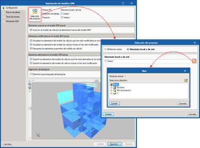
An option has been included to modify the path of the BIM project directory (in the directory where the IFC format files that generate the specific applications of the BIM project are located). In previous versions, the path was fixed. It is recommended the following steps be taken for the path modification to be correct and not lose the connection:
- Copy the BIM project folder
Using the operating system of your computer, copy the folder that contains the BIM project and paste it in its new location. - Update the IFC at each application of the BIM project
Press the “Update IFC” button in each application the IFC is used in, and access the “Project selection” button located in the top part of the “Import of BIM models” panel. - Select the new directory
Select the new path where the folder containing the BIM project is located. - Change the path in the “Open BIM complement for Revit”
If you use the “Open BIM complement for Revit”, you must remember to change the path of the directory where changes in Revit are updated, by doing the following:
- Cancel collaboration
Select the “Cancel collaboration in the Open BIM project” option. - Reconnect in the new directory
Select the “Collaborate in the Open BIM project” option.
- Cancel collaboration
This process must be followed very carefully. If the path of the directory of the project is modified, and a new path is created, which leads to a directory that does not contain the same information as the original project, the system will display error messages due to lack of information. The path must never lead to folders with other projects, nor should the information of the folder that is being moved be modified manually.
The path of the BIM project directory can be modified in CYPE programs that are integrated in the Open BIM workflow (IFC Builder, CYPECAD, StruBIM, CYPELEC, CYPETEL, CYPELUX, CYPESOUND, CYPEFIRE, CYPETHERM) and in the “Open BIM complement for Revit”. In this complement, it was already possible to change the directory as of previous versions, using the procedure indicated in point 4.
CYPECAD
ACI 216.1-07 code for concrete elements
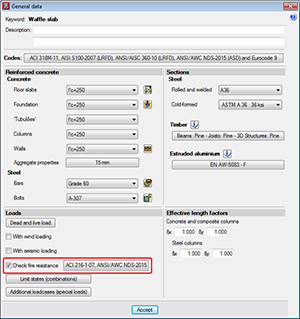
The ACI 216.1-07 code (Code Requirements for Determining Fire Resistance of Concrete and Masonry. Construction Assemblies) has been implemented in CYPECAD.
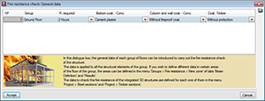
The checks of the ACI 216.1-07 code are carried out automatically when users activate the Check fire resistance box and have selected one of the ACI concrete codes: CIRSOC (Argentina), NSR-10 (Colombia), the ACI code itself, etc.).
As occurs with other codes that have been implemented, with the ACI 216.01-07:
- Users indicate the fire resistance properties: define the required resistance and coatings the program is to design, if necessary.
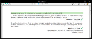
- The check is based on design limits of the elements and the reinforcement cover, which can be increased for greater protection.
- Concrete columns have a specific fire resistance check.
Copy post-tensioned elements
Options have been added to copy post-tensioned elements. These have been included in the “Copy elements of the group”, “Copy symmetrical elements” and “Copy elements in another group” dialogue boxes.
Design of column stirrups
A button has been added in the top part of the column reinforcement editor which allows users to design column stirrups when the longitudinal reinforcement has been modified manually.
Naming of circular column diameters (Ø) with Brazilian codes
When applying Brazilian design codes, the diameter of circular columns is indicated with the Greek letter “Ø” instead of the word “diameter”.
StruBIM Foundations
Analysis and design of mat foundations and slabs bearing on piles
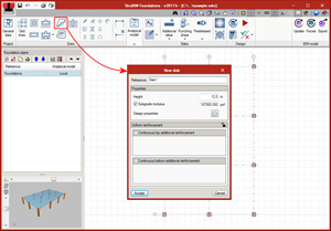
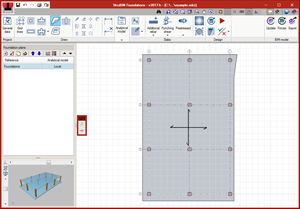
Implemented in the 2017.h version is the design and analysis of mat foundations bearing on the ground and slabs bearing on piles. Using the column or wall supports that have been introduced, or those imported with an “xml” or “ifc” file, users can introduce slabs, openings in slabs and piles as new elements. With these elements, a local analytical model of the foundation plane is generated where the analysis of the forces will be carried out to finally complete the design and check of the slab. As occurs with StruBIM Design, the continuous reinforcement of the slabs can be designed, the punching shear can be designed and checked, and post-tensioned slabs can be defined, analysed and checked.
Element introduction
- Slabs
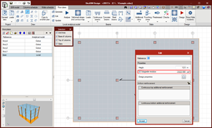
Slabs are introduced on the floor plan by drawing their outline and defining their properties. Users can introduce:- Mat foundations
The subgrade modulus must be defined. - Slabs bearing on piles
No value is assigned to the subgrade modulus (which implies they will not have any external fixity) and the piles on which the slabs will bear are introduced.
- Mat foundations
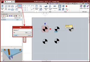
- Piles
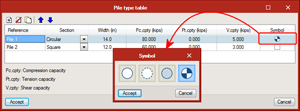
Piles can be introduced at any position of the floor plan. Users can choose the type of pile amongst those defined in the piles table.
Analytical model
Isolated elements (footings and pile caps) are designed and checked directly using the forces defined at the column supports. In the case of slabs, be they mat foundations or slabs bearing on piles, an analysis of the forces must be carried out using a local analytical model.
- Generating the local analytical model
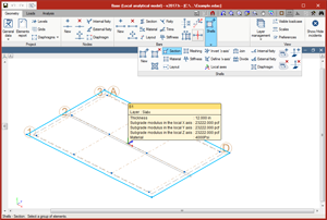
The analytical model is generated automatically. The program allows users to select the discretisation size of the shell in the generating process. Slabs generate shells and the pile supports generate nodes with external fixity. The supports of columns, walls and piles generate non-deformable zones, equivalent to their section, in the slab. - Editing the local analytical model
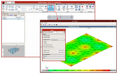
To edit a local model, click on the “Edit” icon. The local model is edited via an interface similar to “StruBIM Analysis”, where users can define the discretisation size of shells, fixity coefficients, stiffness factors, stiffness of the supports, loads, etc. - Updating the local analytical model
The local analytical model can be updated using the “Update” option of the analytical model. This option transfers new or modified data of the elements of the floor plan to the analytical model. For elements whose properties are not the same, StruBIM Foundations displays a warning sign. - Use management of the local model when checking and designing elements
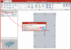
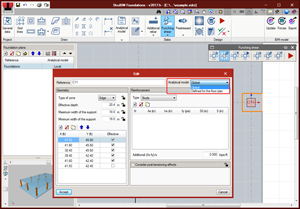
Once the local analytical model has been generated for a floor plan the forces of the mode will be used, by default, to design and check all the elements contained in the plan. Using the “Edit” option of the floor plans list, users can indicate whether the global or analytical model is to be used.
The design and checking process of slabs always uses the local analytical model defined for the floor plan. In punching shear regions, users can select the use of this region in the editing window or before the design process that is launched from the punching shear menu. - Results consultation
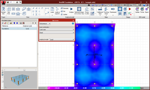
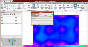
The analysis results of the local model can be viewed from the following windows:
StruBIM Design
Ground bearing slabs
As of the 2017.h version, a subgrade modulus can be assigned to slabs defined in floor plans, regardless of whether they are imported or introduced by users.
The analytical model that is generated based on a mat foundation for which a subgrade modulus has been defined, will be assigned that subgrade modulus in the X, Y and Z directions. This however, can be edited for any direction.
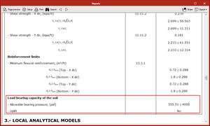
In the “Floor plans” tab, users can consult soil pressure in the contour maps for the different loadcases and combinations. The program checks that allowable bearing pressure defined in “General data” is not exceeded and that there are no uplift points for any combination.
StruBIM Design and StruBIM Foundations
Seismic loadcases
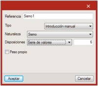
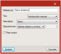
As of the 2017.h version, users can define or import forces in seismic loadcases. Seismic load patterns can include simple seismic load patterns with one or more load arrangements defined by series values, and seismic load patterns defined using envelopes with maximum and minimum values.
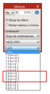
The forces of the elements in loadcases associated with seismic load patterns defined by a “Series of values” can be consulted or defined for each arrangement. In combinations in which this type of loadcase intervenes, each of the layouts defined will be combined with the other terms of the combination.
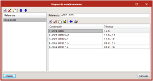
For example, the combination 0.8•D+1•E, where E is a seismic loadcase with 3 load layouts, will generate 3 combinations, one for each layout:
- Combination 1: 0.8•D+1•E1
- Combination 2: 0.8•D+1•E2
- Combination 3: 0.8•D+1•E3
The forces of the elements in loadcases associated with the seismic load patterns defined by “Maximum and minimum values” can be consulted or defined by a group of maximum values and another of minimum values. The design and check of the structural elements are carried out with the combination of each force (maximum or minimum) and the remaining forces (maximums or minimums ).
|
N |
Vx |
Vy |
T |
Mx |
My |
Min. |
Nmin |
Vx,min |
Vy,min |
Tmin |
Mx,min |
My,min |
Max. |
Nmax |
Vx,max |
Vy,max |
Tmax |
My,max |
My,max |
For example, the combination 0.8•D+1•E, where E is a seismic loadcase defined by “Maximum and minimum values”, will generate 64 different force combinations where the maximum or the minimum value of each of the 6 forces of the seismic load pattern will intervene:
- E1 (Nmin; Vx,min; Vy,min; Tmin; Mx,min; My,min)
- E2 (Nmin; Vx,min; Vy,min; Tmin; Mx,min; My,min)
- E3 (Nmin; Vx,min; Vy,min; Tmin; Mx,min; My,min)
CYPELUX, CYPELUX CTE (Spain) and CYPELUX RECS (Portugal)
Display numerical results on the floor plan
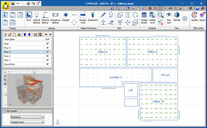
An option has been introduced to display the results obtained at each design point of the zones defined in CYPELUX. This way, as well as being able to visualise the representation of the contour lines and contour maps on plan, it is also possible to inspect the value of each sensor used by the program.
Daylight quotient calculation
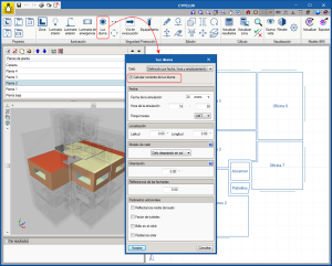
A new option has been added in the “Daylight” panel, which allows users to activate or deactivate the calculation of the daylight quotient, regardless of whether or not the lighting produced due to natural light effects is to be included in the results.
CYPELUX
Optimisation of natural light in accordance with the NF HQE code (Installation in French)
The check: “Optimisation of natural light”, established in the NF HQE code has been implemented. To be able to apply this check, users must have the “Optimisation de l’éclairage naturel suivant la norme NF HQE” permits.
The program calculates the daylight factor at several points of the precinct using the RADIANCE tool. Once calculated, CYPELUX displays the daylight factors on-screen.
If users pace the cursor on a zone, the program displays the level achieved (niveau B, P or TP) for the zone.
CYPELUX generates justification reports for the complete project and for each specific zone. More information can be found in the new features of the 2017.h version on our French webpage.
CYPETHERM HVAC
Space information on floor plans
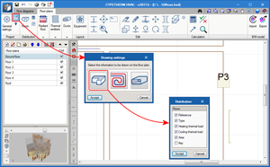
The “Drawing settings” dialogue box (“Floor plans” tab > “Project” section > “Drawing settings” button) has been rearranged. Now there are three buttons to access the drawing preferences of the elements of the installation: “Distribution”, “Radiant floor” and “Ducts”. Users can access the implemented options using the “Distribution” button. Here, the options related to the spaces in the floor plans can be activated. This way, users can choose what information can be visualised on the floor plan, such as the area, etc. The key corresponds to the name of the variable.
As occurs with all tags, it can be moved or hidden using the move tag and hide tag tools.
Representation of equipment on floor plans
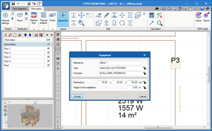
Using the “Equipment” tool, a machine can be represented on the floor plans.
For VRF equipment, if they are assigned a reference that coincides with that of a machine defined in the “Flow diagrams” tab, all the fields containing an open lock will be read and overwritten. The dimensions of all the VRF equipment are defined internally in the program.
Return to the 2017 version download area
Tel. USA (+1) 202 569 8902 // UK (+44) 20 3608 1448 // Spain (+34) 965 922 550 - Fax (+34) 965 124 950
