
![]()
New programs
CYPEFIRE CTE (Spain)
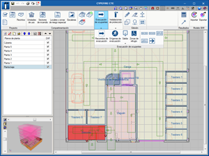
CYPEFIRE CTE is a tool created to help project designers with the design and verification processes of the geometric properties of the building, and fire protection installations. This way, the program performs the necessary checks to ensure the requirements of the CTE DB SI code are met.
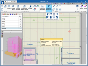
More information on this new CYPE program is available on the CYPEFIRE CTE webpage.
CYPEFIRE Sprinklers
CYPEFIRE Sprinklers is a tool created to design hydraulic networks for fire protection using sprinklers and fire hose reels.
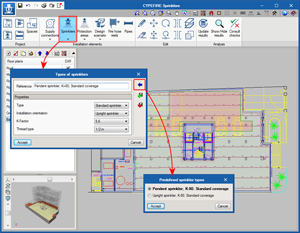
The program carries out the necessary hydraulic calculations and checks to ensure the requirements of the NFPA®13 (National Fire Protection Association) code are met. These include:
- Hydraulic design of any type of any type of network
- Flow and minimum pressure in the sprinklers
- Distribution of the sprinklers
- Maximum allowable distance between sprinklers
- Maximum distance between the sprinklers and the wall
- Design of the tank
- Design of the fire hose reels
CYPEFIRE Sprinklers automatically generates all the technical documents and drawings that are required to justify the requirements of the NFPA®13 code: Analysis of the nodes, Analysis of the pipes and Installation drawings.
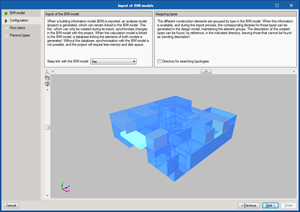
CYPEFIRE Sprinklers is an application that is integrated in the Open BIM workflow. This integration is achieved by importing information files of a previously defined BIM model.
- Imports geometric models included in the spaces using IFC4 format files that have been generated by CAD/BIM programs such as IFC Builder, Allplan, Archicad or Revit.
- Exports, in an IFC file, the information of all the sprinkler system installations so they can be introduced in other programs that work in the Open BIM workflow.
More information on this new CYPE program can be found on the CYPEFIRE Sprinklers webpage.
CYPECAD
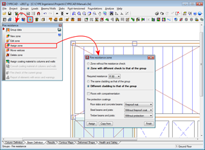
Assign fire resistance check zone
Users could, as of previous versions, create zones with different fire resistance options to those defined in the options of the project in CYPECAD. As of the 2017.g version, the option “Assign zone”, has been added to the fire resistance definition tools. This tool allows users to assign the required resistance and fire protection coatings to several zones, if required. The resistance zones can have the same or different fire protection coatings to those of the group.
Beams at the base of columns with external fixity
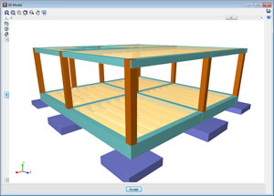
As of the 2017.g version, CYPECAD allows users to analyse the project even if beams (that are not foundation beams, strap beams, supports or walls) have been introduced at the base of columns that have been defined as having external fixity. The program emits a message warning users of this situation, which allows them to ensure the introduction has been carried out intentionally and is not an error.
By introducing these beams at the base of columns with external fixity, users can introduce raised floor slabs containing beams that transmit loads to the columns.
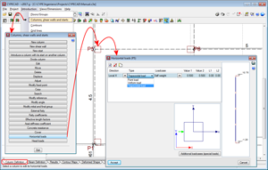
Horizontal trapezoidal loads on columns
Trapezoidal loads have been implemented in the horizontal loads introduction option for columns.
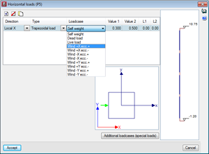
Assign loads to automatic wind load patterns
In previous versions, it was not possible to assign loads defined by users in the wind load patterns that were automatically generated by CYPECAD when wind loads are defined in the “General data” dialogue box (Project > General data). As of the 2017.g version, users can assign an additional load to introduce any of these load patterns in the program.
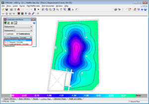
Representation of the U.L.S. of displacement combinations in contour maps
In the previous version (2017.f), the representation of serviceability limit states (S.L.S) of force combinations was implemented in the contour maps. In this version (2017.g), displacement combinations are included.
Warning of repeated column references
As of previous versions, CYPECAD detects if there are any repeated column references when the project is saved (the project is saved manually when users change tabs or the program is closed). As of the 2017.g version, the program indicates which references are repeated.
In projects containing many columns, it may be complicated to visually locate these columns. If users know the repeated references, they can use the “Search” option (Introduction > Columns, shear walls and starts > Search) to quickly locate which columns have been assigned the same reference.
CYPELUX
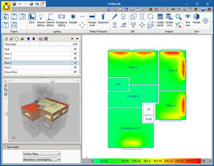
Calculation of the illuminance produced by daylight
As of the 2017.g version, CYPELUX incorporates the calculation of the illuminance produced by natural light. To obtain these values, the CYPELUX project must be associated with a BIM model containing, at least, the geometric definition of the building.
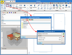
A library is also included in the program, which can be accessed from the toolbar, and contains the types of windows and skylights that are present n the project. Users can indicate the “Transmission grade” and “Refraction index” of the glass.
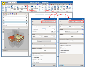
To be able to launch the analysis, as well as having to specify the properties of the glazed openings, the light conditions must be described using the “Daylight” option in the toolbar of the program. Specified in this panel are the daylight parameters such as the type of sky based on the CIE standard, the location of the building and its orientation, which can be obtained from the BIM model, if it has been defined in it.
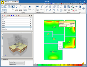
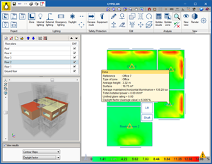
Calculation of the daylight factor
Thanks to the daylight analysis that has been included in CYPELUX, it is now possible to determine the daylight factor values for each project space. The daylight factor expresses the ratio between the illuminance at a point indoors due to natural daylight and the illuminance it would have if there were no obstructions. This coefficient is indicative of the usage level of natural light.
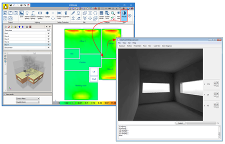
Rendering of the natural light scene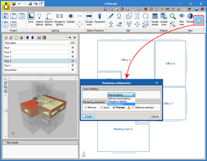
A new option “Natural lighting” as a “Type of lighting” has been added in the “Rendering configuration” panel. This way, it is now possible to select the daylight scene to view the project.
CYPETHERM HVAC
Toshiba variable refrigerant flow (VRF) systems
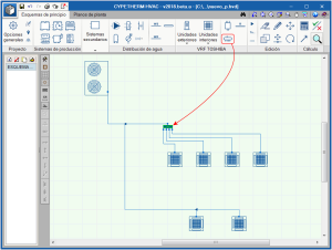
Located in the toolbar of Flow diagram tab is the Toshiba VRF systems block, which contains the elements required to introduce a variable refrigerant flow system of this manufacturer.
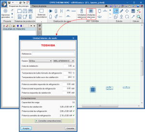
Interior units
Interior units must be located in the same space to be conditioned, and can be cassette, duct, wall, floor or ceiling-type units.
For each type of unit, there is a series of sizes with a nominal heating and cooling power. This nominal power will be corrected by the program depending on the indoor design conditions, pipe lengths and, finally, the capacity of the selected outdoor unit. The panel contains the thermal loads and the design conditions of the space to be conditioned. The program checks that the selected unit is capable of taking on those loads.Exterior units
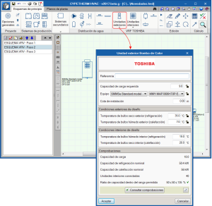
All the indoor unit network is connected with pipes to an outdoor machine, which can be a heat pump (2 pipes), or with heat recovery (3 pipes). That which is selected will determine the type of system.
- Exterior unit, heat pump
In this 2-pipe system, the outdoor unit will provide cold to all the indoor units at the same time, or heat to all the indoor units. - Exterior unit with heat recovery
In this type of 3-pipe system, the machine will provide cold to some indoor units and heat to other indoor units simultaneously. For this to be possible, a flow selector unit must be placed upstream of each indoor unit.
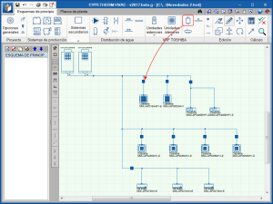
Refrigerant pipes
The pipes are drawn schematically and the program selects their diameters depending on the sum of the capacity coefficients (i.e. the thermal capacity they transport) of the units located downstream and the location of the pipe in the system.
Flow selector units
Flow selector units, also known as boxes, are devices placed in 3-pipe systems, i.e. when the exterior unit is a “with heat recovery” type unit. This device has 2 pipes on one side (which connects to the interior unit) and 3 pipes on the other. Its function is to feed the interior unit with gas or refrigerant, depending on the thermal needs at the time.
Branch circuits
Each time a main pipe splits to create a branch, it does so with a branch circuit. No icon exists for this element as the program automatically places a branch circuit and selects the required size at each branch.
Manifolds
Occasionally, the main pipe has to feed several interior units located at a similar distance. For these cases, it is best to place a manifold with 4 or 8 outlets instead of having several branches that are very close in the main pipe.
Results output
Upon selecting the “Reports” button, the program generates a results report containing all the information regarding the system: element quantities, requirement checks, corrected heating and cooling capacities, circuit diagram.
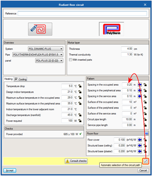
Radiant floors
Circuit quantity details per roll
The required tubing rolls for the designed installation are now included in the radiant floor report, indicating the circuits making it up (including the zone to which they belong) and the length left over from each roll.
Design of the circuit paths
A new option in which the program automatically selects the best path of the circuits in occupied zones and peripheral zones, for the defined conditions, has been implemented in the editing panel of the radiant floor circuits. This option is currently only available for Polytherm manufacturer circuits.
CYPETHERM HE Plus, CYPETHERM REC Plus and CYPETHERM EPlus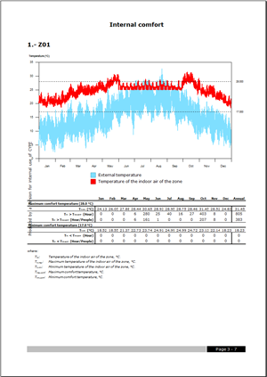
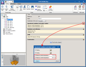
Indoor comfort temperatures and report
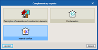
A report has been implemented for the analysis of the results of the energy simulation carried out in the programs of the CYPETHERM group that wok with EnergyPlus (CYPETHERM EPlus, CYPETHERM HE Plus – Spain – and CYPETHERM RECS Plus – Portugal). This report allows users to analyse the evolution of the indoor temperature of the zones with respect to the outdoor temperature. This way, they can evaluate, for example, the temperature in spaces with free fluctuation or check that the systems that have been defined meet the requirement of maintaining the indoor temperature within the defined range. The program also counts the number of hours that the indoor temperature lies outside the comfort limits, and distinguishes between the total number of hours during which this occurs whilst the zone is being occupied. The comfort limits can be defined for air conditioning and for heating.
Arquimedes
New report templates
New report templates have been added for Bolivia, Mexico, Peru and Spain.
More information on these new templates can be found here.
Return to the 2017 version download area
Tel. USA (+1) 202 569 8902 // UK (+44) 20 3608 1448 // Spain (+34) 965 922 550 - Fax (+34) 965 124 950