
(8th August 2013)
![]()
- Code implementation and improvements in its application
- CYPECAD
- Interaction of the structure with the construction elements
- Advanced beam editor
- Vertical openings in beams
- Horizontal and vertical openings in beams are not eliminated after analysing or redesigning
- Capacity design criteria for seismic design with CIRSOC 103-2005 (Argentina)
- Analysis time optimisation during the design of columns using the IS 456: 2000 code (India)
- Post-tensioned slabs
- Export to Tekla Structures (CYPECAD and Metal 3D)
- CYPECAD MEP
- Thermal analysis for Italy
- D.P.R. 2 aprile 2009, n.59
- Selection of heating systems with biomass boilers to carry out the thermal analysis
- Thermal analysis for France
- Air conditioning. Thermal loads represented on-screen using contour lines
- Solar thermal energy installation for the production of hot sanitary water for CYPECAD MEP installed in French
- Export to IFC
- Return to Download Area
Code implementation and improvements in its application
Concrete code
ACI 318M-08 (USA), Nch430.Of2008 (Chile), NTE E.060: 2009 (Peru) and NSR-10 (Columbia)
The tool, Strut3D, was implemented in the 2013.e version, and allows users to check (in CYPECAD and Metal 3D – using the Pile Caps module) pile caps using a general analysis method that analyses the D regions of the reinforced concrete using a strut and tie model. This tool was only available for use with the EHE-08 (Spain) code. Now, with the 2014.b version, the tool has been implemented for use with the following concrete codes:
- ACI 318M08 (USA)
Building Code Requirements for Structural Concrete.
- NCh430.Of2008 (Chile)
Norma Chilena official NCh430.Of2008.
- NTE E.060: 2009 (Peru)
Reglamento Nacional de Edificaciones. Norma E.060 Concreto Armado (2009).
- NSR10 (Columbia)
Reglamento Colombiano de Construcción Sismo Resistente NSR-10.Título C – Concreto structural.
IS 456: 2000 (India)
Indian Standard. Plain and reinforced concrete code of practice (Fourth Revision).
This code was already implemented in CYPECAD. Now, with the 2014.b version, the time required for the design of the concrete columns has been optimised.
Cold-formed steel code
S280GD and S320GD steels for Eurocode 3 (EU) and EAE (Spain)
Steel types S280GD and S320GD have been implemented for Eurocode 3 (including the National Application Documents or general document adaptations for Bulgaria, France, Italy and Portugal) and EAE (Spain).
Loads on structures. Seismic loads
CHOC-08 (Honduras)
Código Hondureño de la Construcción. Normas Técnicas. Capítulo 1. Cargas y fuerzas estructurales. Diseño por Sismo.
Implemented in CYPECAD and Metal 3D.
The dynamic analysis method (spectral modal) or static analysis method (equivalent lateral force) proposed by the CHOC-08 can be selected in both programs. The analysis method (dynamic or static) can be selected using the Analysis method option in the dialogue box in which the seismic action is defined.
When the seismic design is carried out using the dynamic analysis method (modal spectral), CYPECAD considers the correction due to base shear.
CIRSOC 103-2005 (Argentina)
Normas Argentinas para ConstrucciónSismorresistente. Parte II: Construcciones de Hormigón Armado.
The reinforcement ductility criteria and the capacity design criteria for seismic design indicated in CIRSOC-103 2005 were implemented in the 2013.l version. These criteria are applied in CYPECAD when users select CIRSOC 201-2005 and combine it with CIRSOC 103-1991 or CIRSOC 103-2008.
Now, as of the 2014.b version and to calculate the overresistance factors for seismic capacity checks carried out by the Advanced beam editor of CYPECAD, the overresistance moments of the beams are considered at the axes.
Additionally, as of the 2014.b version, the seismic design criteria checks carried out by the Advanced beam editor, and check of the maximum diameter of the continuous reinforcement via internal nodes have been added.
СНиП II-7-81* (Russia)
СТРОИТЕЛЬСТВО В СЕЙСМИЧЕСКИХ РАЙОНАХ. Актуализированная редакция
Construction in seismic regions. Updated edition
Implemented in CYPECAD and Metal 3D.
Thermal insulation
D.P.R. 2aprile 2009, n.59 (Italy)
Regolamento di attuazione del D. Lgs. 192 sul rendimento energetico in edilizia.
This Decree has been implemented for CYPECAD MEP for Italy (Studio termico tab). More information on this implementation can be found in the Thermal analysis for Italy section in this webpage.
CYPECAD
Interaction of the structure with the construction elements
Calculation of the properties of the masonry construction elements
The homogenised values of the properties of the construction elements that are introduced in CYPECAD, to consider their effect in the dynamic analysis of buildings exposed to seismic action, are, as of the 2014.a version: the Thickness of the masonry, Modulus of elasticity X, Modulus of elasticity Y, Shear modulus XY, Poisson’s ratio XY and the Surface load.
All this data is introduced in the Masonry properties – homogenized values – (Beam Definition tab > Loads > Construction elements > Add or Edit option > edit selected type button ![]() or edit type list button
or edit type list button ![]() and add
and add ![]() ). It is the manufacturers, who due the tests they have carried out on their products, will be able to provide more exact values.
). It is the manufacturers, who due the tests they have carried out on their products, will be able to provide more exact values.
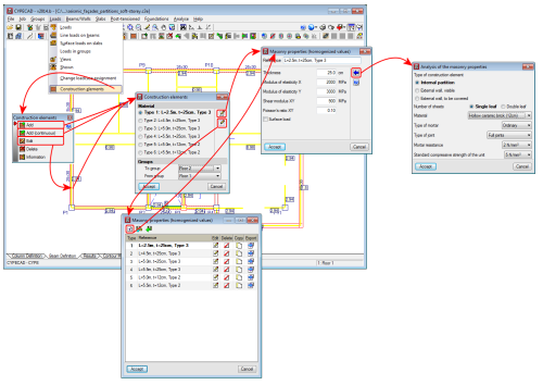
For those cases in which the manufacturers have not provided the required data, a tool has been implemented in the 2014.b version that calculates the homogenised values of the masonry properties based on geometric and resistance data that users can know more easily. This tool is accessed from the previously mentioned dialogue box: Masonry properties – homogenized values, selected using the Property analysis button (![]() ).
).
The properties required by the tool are:
- Type of construction element
- Internal partition
- External wall, visible
- External wall, to be covered
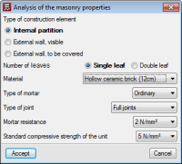 Number of leaves (single or double)
- Material
- Type of mortar
- Type of joint
- Mortar resistance
- Standard compressive strength of the unit
In order to define the material, type of mortar, type of joint, mortar resistance and the standard compressive strength of the unit, users must select the adequate option amongst those offered by the program in a drop-down list.
Advanced beam editor
Vertical openings in beams
Implemented in the previous version (2014.a) was the introduction and check of horizontal openings in beams, for dropped rectangular, “L” or “T” sections (without lattice reinforcement) using the Advanced beam editor of CYPECAD and Continuous beams.
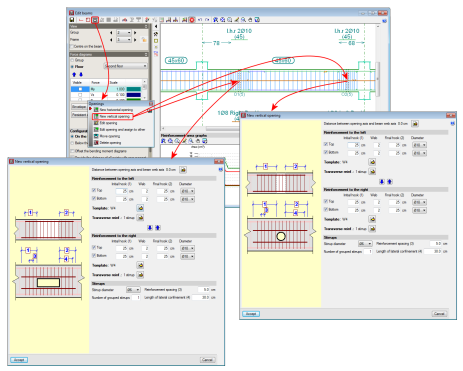
Now, with the 2014.b version, vertical openings (rectangular or circular) can be introduced in flat or dropped rectangular, “L” or “T” beams (without lattice reinforcement).
A new option, New vertical opening, has been implemented to introduce the vertical openings, within the Openings dialogue box (Edit a beam from the Results tab of CYPECAD using the advanced beam editor > select the ![]() button of the editor).
button of the editor).
The program allows for vertical openings to be introduced in the flanges and webs of flat and dropped beams, as long as the following conditions are met:
- The transverse dimension of the vertical opening must be less than one third of the width of the web or less than two thirds of the width of the flange, depending on the zone in which the opening is situated.
- The length of the opening must be less than the width of the web and the depth of the beam.
- The position of the vertical opening must guarantee that the cover is respected at all the surfaces of the opening.
- The free distance between a vertical opening and the support of the beam must be greater than the lateral confinement length of the opening.
Furthermore, the free distance between consecutive openings, be they horizontal or vertical, must be greater than two times the depth of the beam and greater than the width of the web of the beam.
Neither horizontal nor vertical openings may be introduced in the confinement zones established in the selected seismic code.
The resulting section of the beam, having applied the reduction due to the presence of the opening, will be checked using the criteria of the selected code as will, besides the reinforcement of the beam, the reinforcement provided in the opening.
The conditions of the position and dimensions of the openings of the horizontal openings can be consulted in the new features of the 2014.a version.
When a vertical opening is introduced and cuts the reinforcement of the frame, the program emits a warning informing users that the arrangement of the reinforcement bars proposed by the program is to be revised, once the opening has been introduced and checked, as there may be a simpler reinforcement arrangement that can be executed on site. Users could even position some of the additional reinforcement bars of the frame in a second layer so the reinforcement arrangement of the opening would be easier to execute.
The remaining edition and check options of the Ultimate Limit States (U.L.S.) of the openings, operate in the same manner as for horizontal openings and can be consulted in the Advanced beam editor. Horizontal openings in beams section in the new features of the 2014.a version.
Please bear in mind that neither the horizontal nor vertical openings are considered during the analysis phase, hence their position and dimensions are restricted (as has been indicated previously in their introduction conditions) so the forces that are obtained can be considered valid.
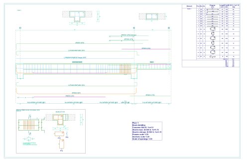
The reinforcement details of the vertical openings are generated automatically within the details of the frame, in the same way as for horizontal openings.
Horizontal and vertical openings in beams are not eliminated after analysing or redesigning
As of the 2014.b version, the horizontal and vertical openings are not eliminated even if the job is analysed or the frame is redesigned. The program rechecks the openings of a frame when they are edited by users.
Capacity design criteria for seismic design with CIRSOC 103-2005 (Argentina)
Information on the improvements that have been carried out upon applying CIRSOC 103-2005 when applying a seismic analysis can be found in the section on Loads on structures. Seismic loads - CIRSOC 103-2005 (Argentina) of this webpage.
Analysis time optimisation during the design of columns using the IS 456: 2000 code (India)
The time required to design the concrete columns, especially using the IS 456: 2000 Indian code, has been optimised.
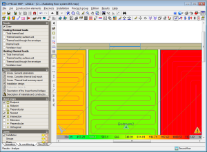
Post-tensioned slabs
Move tendon anchorages
A new option Move anchorages, has been implemented in the Post-tensioned dialogue box (Beam Definition tab or Results tab > Post-tensioned > Post-tensioned > Move anchorages) which allows users to move the anchorage in the direction of the tendon (by selecting the anchorage to be moved with the left mouse button) or move the both anchorages and the tendon perpendicularly to it (if any part of the tendon, except its ends, is selected).
Export to Tekla Structures (CYPECAD and Metal 3D)
The 2014.b version of CYPECAD and Metal 3D allows for the export of jobs to versions 18 and 19 of Tekla Structures.
CYPECAD MEP
Thermal analysis for Italy
D.P.R. 2 aprile 2009, n.59
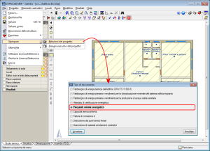
The 2014.b version of CYPECAD MEP for Italy (Studio termico tab) verifies that Decree D.P.R. 2 aprile 2009 n.59 (Regolamento di attuazione del D. Lgs. 192 sul rendimento energetic in edilizia) is met. This decree defines the general criteria, the analysis methodology and minimum requirements for a coordinated homogenous application of the code for the energy efficiency of buildings.
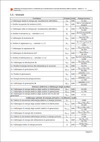
CYPECAD MEP verifies the requirements are met and generates a report (File > Stampare > Relazioni del progetto > Requisiti minimi energetici) with the specifications prescribed in this decree.
Selection of heating systems with biomass boilers to carry out the thermal analysis
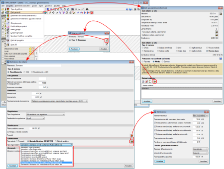
The 2014.b version includes the possibility to select heating systems using biomass boilers with air and water thermovector fluid, loaded manually and automatically; so they are taken into account in the primary energy demand and efficiency analysis of the heating systems of the building. This analysis can be carried out using pre-calculated tabulated values or using the method of the Direttiva 92/42/CEE, as indicated in the UNI/TS 11300-4 code (Utilizzo di energie rinnovabili e di altri metodi di generazione per la climatizzazione invernale e per la produzione di acqua calda sanitaria).
Users can select the type of biomass boiler and the analysis method (Direttiva 92/42/CEE or Prospetti) in the Definizione dei sistemi dialogue box (Studio termico tab > Dati generali > edit or add in the Sistemi collettivi section > edit or create type > select a type of biomass boiler from the Generazione section in the Definizione dei sistemi dialogue box).
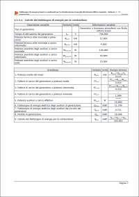
Using the edit button in the Generazione section in the Definizione dei sistemi dialogue box, the data of the selected heating system can be defined.
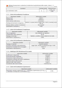
The results can be consulted in the Fabbisogni di energia primaria e rendimenti per la climatizzazione invernale del sistema edifico-impianto report (Studio termico tab > File > Stampare > Relazioni del progetto).
Thermal analysis for France
The following updates have been implemented in the Étude thermique tab of CYPECAD MEP for France:
- Version update of the analysis motor of the RT 2012 code: Coeur de calcul de la RT 2012, V1.1.6.3
- Version update of the XML file of the RT 2012 code: Fiche Standardisée RT 2012, 1163_V1.5
Air conditioning. Thermal loads represented on-screen using contour lines
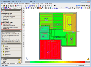
The 2014.b version includes a practical and important new feature which allows users to know the thermal loads of the precincts of a floor of the building at a single glance. It consists of a display, using contour lines, of the heating and cooling thermal loads that have been calculated for each precinct.
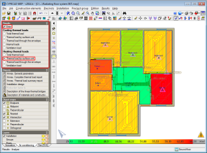
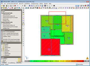
Once the analysis has been carried out in the Air conditioning tab, users can activate the Draw option, within the new Results section in the lateral menu. By activating this option, the data that can be represented on-screen related to the heating and cooling thermal loads is displayed:
- Cooling thermal loads
- Total thermal load
- Thermal load by surface unit
- Thermal load through the envelope
- Internal loads
- Ventilation load
- Heating thermal loads
- Total thermal load
- Thermal load by surface unit
- Thermal load through the envelope
- Ventilation load
The thermal cooling or heating loads can be selected if they have been activated for the analysis in the Load calculation section of the General data dialogue box (Job > General data). The “Air conditioning” option in this dialogue box activates the analysis of both thermal loads and the “Cooling” and “Heating” options only activate the loads their name indicates.
The external, inhabitable, or habitable precincts for which the option “Not air conditioned” has been activated, will appear in white when either the cooling or heating thermal loads are selected. Habitable precincts, whose design parameter for the thermal analysis has the option “Only heated” activated, will appear in white when any type of cooling thermal load has been activated.
As with any data representation carried out by CYPE programs using contour lines, a scale of values of the colours that are displayed is present in the bottom part of the screen. The colour range used in the representation can be changed using either of the two colour palettes in the Colours for the representation of contour maps dialogue box (“General configuration button ![]() ” located in the top right-hand corner of the screen > “Colours for the representation of contour maps” option). The palette with least colours allows for the texts to be visualised better on-screen, although the precincts may be represented with colours which are similar to each other. The palette with most colours may hinder the reading of some texts on-screen but the precincts are represented with a more varied colour range.
” located in the top right-hand corner of the screen > “Colours for the representation of contour maps” option). The palette with least colours allows for the texts to be visualised better on-screen, although the precincts may be represented with colours which are similar to each other. The palette with most colours may hinder the reading of some texts on-screen but the precincts are represented with a more varied colour range.
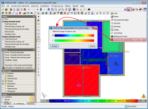
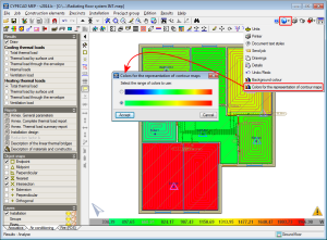
The maximum numerical value that is visible on-screen always corresponds to the colour at the right-hand end of the selected palette and the minimum value with that at the other end. This allows the precincts which are represented on-screen with similar colours to change and so can be better distinguished between one another upon zooming in.
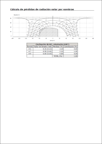
Solar thermal energy installation for the production of hot sanitary water for CYPECAD MEP installed in French
As of previous versions, CYPECAD MEP, allows users to design a solar thermal energy installation, for individual or collective use, for the production of hot sanitary water for Spain and Portugal. In the 2014.a version, these installations were also implemented for other Spanish and Portuguese-speaking countries for which CYPE’s Price generator is available and the design of the installation was adapted so it would be valid for any latitude.
Now, in the 2014.b version, the design of solar thermal energy installations, for individual or collective use, for the production of hot sanitary water has been implemented for French-speaking countries for which the Price generator is available (Algeria, Cameroon, Ivory Coast, France, Gabon, Morocco, Republic of Congo and Senegal).
Therefore, as of the 2014.b version, CYPECAD MEP allows for the design of these installations for the following countries;
- Africa
- Angola
- Algeria
- Cape Verde
- Cameroon
- Ivory Coast
- Gabon
- Morocco
- Mozambique
- Republic of Congo
- Senegal
- America
- Argentina
- Brazil
- Chile
- Colombia
- Ecuador
- Mexico
- Peru
- Europe
- France
- Portugal
- Spain
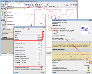
As occurs with the other countries which already included the design of a solar thermal energy installation for the production of hot sanitary water, the countries, which as of the 2014.b version, can design a solar thermal energy installation, allow for the climatic data of the location of the building to be edited from the Solar thermal tab (including the monthly values for the External temperature and the Monthly average daily global irradiation on horizontal surfaces).
Export to IFC
Thickness of the air conditioning and ventilation ducts
The export to IFC format (Industry Foundation Classes) carried out by CYPECAD MEP, now includes the thickness of the air conditioning and ventilation ducts that have been designed by the program.
Tel. USA (+1) 202 569 8902 // UK (+44) 20 3608 1448 // Spain (+34) 965 922 550 - Fax (+34) 965 124 950