
New features and download of the 2013.l version
![]()
- New features in CYPECAD
- Application of the concrete and seismic codes of Argentina in CYPECAD (CIRSOC 201-2005, CIRSOC 103-1991, CIRSOC 103-2005 and CIRSOC 103-2008)
- Seismic analysis with force amplification in open floors or with partitions that are less rigid than on other floors
- Post-tensioned floor slabs
- Advanced beam editor of CYPECAD
- New features in CYPECAD MEP
Code implementations and improvements in their application
Concrete code
CIRSOC 201-2005 (Argentina)
Reglamento Argentino de Estructuras de Hormigón.
This concrete code was already implemented in CYPECAD and Metal 3D as of previous versions. As of the 2013.l version, if users select the CIRSOC 201-2005 code and combine it with CIRSOC 103-1991 (current seismic code of Argentina) or CIRSOC 103-2008 (seismic code which is due to substitute the CIRSOC 103-1991 code), CYPECAD’s Advanced beam editor and column editor may also be used.
Additionally, the U.L.S. reports for columns and beams that are generated by these advanced editors, include reinforcement ductility criteria and the capacity design criteria for seismic design (bending and shear for the seismic design of concrete supports, and capacity design criteria for shear for the seismic design of concrete beams) indicated in the CIRSOC 130-2005 code (Normas Argentinas para Construcción Sismorresistente. Parte II: Construcciones de Hormigón Armado).
The CIRSOC 103-2005 and CIRSOC 103-2008 codes have now been implemented in CYPECAD (as indicated in Loads on structures. Seismic loads). Application of the CIRSOC 103-2005 code is compulsory as of January 2013 whereas CIRSOC 103-2008 is a project code that will substitute CIRSOC 103-1991.
By implementing these seismic codes in CYPECAD, CYPE software is the first structural analysis program that contemplates analysis and design procedures using CIRSOC 103-2005 and CIRSOC 103-2008.
More information on these codes can be found in the section on Application of the concrete and seismic codes of Argentina in CYPECAD in the New features of CYPECAD.
Loads on structures. Seismic loads
CIRSOC 103-2008 (Argentina)
Normas Argentinas para Construcción Sismorresistente – Proyecto de Reglamento CIRSOC 103, Parte I: Construcciones en general.
The 2013.l version of CYPECAD includes the CIRSOC 103-2008 code (code that will substitute the CIRSOC 103-1991 code) to be used together with the CIRSOC 201-2005 concrete code (Reglamento Argentino de Estructuras de Hormigón).
The combination of CIRSOC 103-2008 or CIRSOC 103-1991 together with the CIRSOC 201-2005 concrete code implies the application of reinforcement ductility criteria and the capacity design criteria for seismic design indicated in the CIRSOC 130-2005 code (Normas Argentinas para Construcción Sismorresistente. Parte II: Construcciones de Hormigón Armado), whose application is compulsory as of January 2013. These criteria are justified in the U.L.S. reports generated by the Advanced beam editor and column editor of CYPECAD.
CIRSOC 103-2005 (Argentina)
Normas Argentinas para Construcción Sismorresistente. Parte II: Construcciones de Hormigón Armado.
The 2013.l version of CYPECAD includes the CIRSOC 103-2005 seismic code. This code contemplates reinforcement ductility criteria and the capacity design criteria for seismic design, which are to be used with the CIRSOC 201-2005 concrete code (Reglamento Argentino de Estructuras de Hormigón). Application of the CIRSOC 103-2005 seismic code is obligatory as of January 2013.
Users do not select to apply the CIRSOC 103-2005 code in the program. The combination of the CIRSOC 201-2005 concrete code together with the CIRSOC 103-1991 (current seismic code of Argentina) or CIRSOC 103-2008 (seismic code which is due to substitute the CIRSOC 103-1991 code) implies the application of reinforcement ductility criteria and the capacity design criteria of the CIRSOC 103-2005 code.
More information on these codes can be found in the section on Application of the concrete and seismic codes of Argentina in CYPECAD in the New features of CYPECAD.
CSCR-2010 (Costa Rica)
Código Sísmico de Costa Rica 2010.
This concrete load was already implemented in CYPECAD and Metal 3D as of previous versions. As of the 2013.l version, if users select the CSCR-2010 code and combine it with the ACI 318-08 (USA) concrete code or NCh430.Of2008 (Chile) concrete code, CYPECAD’s Advanced beam editor and column editor may also be used.
Additionally, the U.L.S. reports for columns and beams that are generated by these advanced editors, include the capacity design criteria for bending and shear for the seismic design of concrete supports, and capacity design criteria for shear for the seismic design of concrete beams.
ASCE 7-05 (USA); IBC 2009 (USA); 2011 PRBC (Puerto Rico). Static seismic loads and correct due to base shear
- ASCE 7-05 (USA)
Minimum Design Loads for Buildings and Other Structures
- 2009 IBC (USA)
International Building Code.
- 2011 PRBC (Puerto Rico)
Puerto Rico Building Code.
These codes were already implemented in CYPECAD and Metal 3D as of previous versions for use with the dynamic analysis method (spectral modal).
For this code, the 2013.l version includes in CYPECAD:
- A static analysis method (equivalent lateral force)
Users can select the analysis method (dynamic or static) using the Analysis method option within the dialogue box in which seismic action is defined.
- The correction due to base shear
This correction is applies when the seismic design is carried out using the dynamic analysis method (spectral modal).
Thermal insulation
EN ISO 10077-1
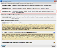
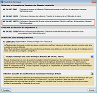
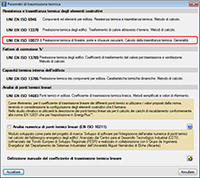
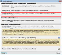
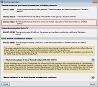
EN ISO 10077-1 has been implemented in the Air Conditioning tab of CYPECAD MEP to calculate, in accordance with this code, the thermal transmittance coefficient for windows and the linear thermal bridge between the carpentry and glazing.
Reference to this code can be seen in the Thermal parameters dialogue box (Job > Thermal parameters in the Air Conditioning tab). Depending on the country that is selected upon creating the job, the corresponding code adaptation shall be applied:
- Spain
- UNE EN ISO 10077-1
Características térmicas de ventanas, puertas y contraventanas. Cálculo del coeficiente de transmisión térmica. Parte 1: Método simplificado. (ISO 10077-1)
- France
- NF EN ISO 10077-1
Performance thermique des fenêtres, portes et fermetures. Calcul du coefficient de transmission thermique. Partie 1: Méthode simplifiée. (ISO 10077-1)
- Italy
- UNI EN ISO 10077-1
Prestazione termica di finestre, porte e chiusure oscuranti. Calcolo della trasmittanza termica. Generalità. Parte 1: Metodo semplificato (ISO 10077-1).
- Other countries
- EN ISO 10077-1
Thermal performance of windows, doors and shutters – Calculation of thermal transmittance. Part 1: Simplified method. (ISO 10077-1).
New features in CYPECAD
Application of the concrete and seismic codes of Argentina in CYPECAD (CIRSOC 201-2005, CIRSOC 103-1991, CIRSOC 103-2005 and CIRSOC 103-2008)
When users select the CIRSOC 201-2005 code (Reglamento Argentino de Estructuras de Hormigón) CYPECAD then allows for the following seismic codes to be selected:
- CIRSOC 103-1991
Normas Argentinas para Construcción Sismorresistente. Reglamento CIRSOC 103 Parte I: Construcciones en general.
- CIRSOC 103-2008
Normas Argentinas para Construcción Sismorresistente. Proyecto de Reglamento CIRSOC 103, Parte I: Construcciones en general.
The CIRSOC 103-2008 code is due to replace the CIRSOC 103-1991 code, which is still in force.
In both cases (and even though CIRSOC 103-1991 contains reinforcement ductility criteria), the reinforcement ductility criteria and capacity design criteria for seismic design of CIRSOC 103-2005 (Normas Argentinas para Construcción Sismorresistente. Parte II: Construcciones de Hormigón Armado) are applied. Capacity design criteria is a new feature of CIRSOC 103-2005 and this code is compulsory as of January 2013. The ductility criteria and capacity design criteria are justified in CYPECAD in the U.L.S. reports generated by its Advanced beam editor and column editor.
The CIRSOC 103-2005 seismic code combined with the CIRSOC 103-1991 or CIRSOC 103-2008 seismic codes, and the CIRSOC 201-2005 concrete codes are complex to apply. This, together with the absence of structural analysis programs that contemplate this code combination, has resulted, in many cases, in them not being applied correctly.
The 2013.l version of CYPECAD includes the implementation of the CIRSOC 103-1991 and CIRSOC 103-2008 seismic codes. Now, using the CIRSOC 201-2005 concrete code (combined with the CIRSOC 103-1991 and CIRSOC 103-2005 seismic codes, or the CIRSOC 103-2008 and CIRSOC 103-2005 seismic codes), CYPECAD becomes the first structural analysis program that contemplates analysis and design procedures using this code combination.
CYPECAD also allows users to select the revoked concrete code; CIRSOC 201-1982 (Proyecto, Cálculo y Ejecución de Estructuras de Hormigón Armado y Pretensado), and hence, be able to check projects which were designed in accordance with it.
Selection of CIRSOC 201-1982 only allows for the CIRSOC 103-1991 seismic code to be selected, together with its reinforcement ductility criteria.
In CYPECAD, the revoked CIRSOC 201-1982 code is not prepared for use with its advanced beam and column editors, and so, even though the program analyses and designs in accordance with that code, it does not generate Ultimate Limit State (U.L.S.) justification reports.
Seismic analysis with force amplification in open floors or with partitions that are less rigid than on other floors
 It is vitally important to consider the effect non-structural elements (façades and partitions) have on the behaviour of a building exposed to seismic action, especially when open floors are present or a floor contains partitions and façades that are less rigid than those on other floors.
There are design codes that oblige project designers to contemplate the absence or reduction of the stiffness of the partitions and façades on specific floors, by applying moment and shear amplification factors to columns, beams, walls and shear walls situated on floors with less stiffness than the rest when resisting the horizontal displacements caused by seismic action. Examples include IS 13920 (India) -Soft Storey- or Proyecto de Reglamento CIRSOC 103-2008 (Argentina). Logically, the tendency of standards and codes which do not contemplate these effects is to gradually take them into account.
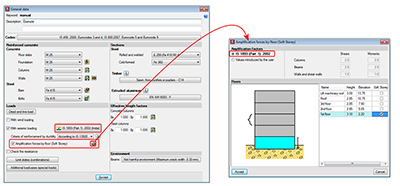
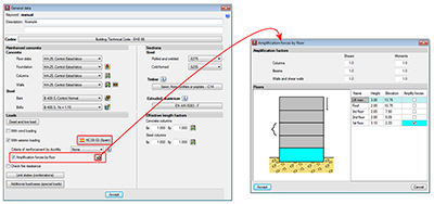
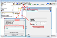
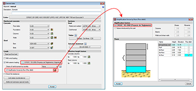 The 2013.l version of CYPECAD allows for moment and shear amplification factors to be applied to columns, beams, walls and shear walls situated on floors chosen by users, regardless of the selected code. To do so, the option Amplification forces by floor has been implemented n the General data dialogue box (Job > General data). Upon activating this option, a dialogue box appears with the same name. If the selected code contemplates the reduced floor stiffness effect due to weaker partitions, the program displays the corresponding moment and shear force amplification factors, which are then applied to the selected floors. Users also have the choice to indicate their own amplification factors. If the selected code does not contemplate these effects, the program allows users to introduce the values they wish for the floors they select.
This method to consider the effect the absence of partitions and façades on specific floors may have when exposed to seismic action, is an approximation to the real behaviour of the building.
 In an upcoming version, CYPE will implement a tool that contemplates, in a more precise manner, the influence the distribution of the partitions and façades has on the building. This tool is the result of a R+D+I project CYPE is developing in collaboration with the Centro Internacional de Métodos Numéricos en Ingeniería (CIMNE) of the Universidad Politécnica de Cataluña (UPC), and is financed by the Centro para el Desarrollo Tecnológico Industrial (CDTI) and co-financed by the European Regional Development Fund (ERDF). The aim of this R+D+I project is to develop a dynamic analysis method for buildings exposed to seismic action which includes the effects of the construction elements used in the partitions and façades, and implement them in a design and analysis software tool. This tool is to satisfy the productivity and safety criteria required for the structural project of a building, in other words, ensure the time required to analyse the job is reasonable.
Post-tensioned floor slabs
Specific parameters for each span of the tendon
The 2013.l version includes a new option; Specific parameters for each span of the tendon. This option is located in the dialogue in which tendons are edited (Beam Definition tab > Post-tensioned > Edit a tendon). Within this dialogue, users can select three options in the Layout section:
- General job parameters (existing option)
This option displays, at information level, the parameters that have been defined in the Options dialogue box. Upon selecting this option, the general parameters of the job are assigned to the tendons being introduced or under edition.
- Particular tendon parameters (existing option)
This option opens a dialogue box where the layout parameters of the tendons being introduced or under edition. By selecting this option, the particular parameters are assigned to those tendons.
- Specific parameters for each span of the tendon (new option implemented in the 2013.l version)
Using this option, users can edit each span of the tendon, so different properties can be assigned to the layout of each span. Each span can be defined as curved or straight. If it is defined as curved, the properties of the layout that can be modified are: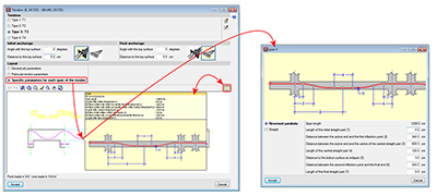
- Span length
- Length of the initial straight part
- Distance between the active end and the first inflection point
- Distance between the active end and the centre of the central straight part
- Length of the central straight part
- Distance to the bottom surface at midspan
- Distance between the second inflection pont and the final end
- Length of the final straight part
When this option is selected, and if users place the mouse cursor on a span of the longitudinal section displayed in the edition dialogue box of the tendon, an information box appears indicating the properties of the span. By clicking on it with the left mouse button, these properties can be edited.
Advanced beam editor of CYPECAD
Elimination of the shift of the bending moment diagrams with the IS 456:2000 (India) code.
When the selected concrete code in CYPECAD is the IS 456: 2000 (India) code, the values of the bending moments and representation of the bending moment diagrams do not appear shifted.
Layout configuration of the grouped frame references in the frames drawings.
 The option: Arrangement of references in grouped frames (File > Print > Job drawings > Add button > Select Frames drawing in “Drawing type” > Configure button > General options tab) has been implemented, which allows for the references of the grouped frames to be placed next to one another (option: Horizontal) or underneath the preceding reference (option: Vertical).
New features in CYPECAD MEP
Air conditioning and thermal analysis
 Implementation of the EN ISO 10077-1 code
EN ISO 10077-1 has been implemented in the Air Conditioning tab of CYPECAD MEP to calculate, in accordance with this code, the thermal transmittance coefficient of windows and the linear thermal bridge between the carpentry and glazing.
More information on this implementation can be found in the section on Thermal insulation, EN ISO 10077-1 on this webpage.
Air conditioning. Geothermal energy harvesting systems
Circulation pump in the energy harvesting system
As of the 2013.l version, the program allows users to introduce circulation pumps (Installation > Water conducting systems > Circulation pump) in the geothermal energy harvesting system, between the manifold and the heat pump.
Head loss in the manifolds of the energy harvesting system
Now, in the 2013.l version, the head loss of the manifolds of the energy harvesting system is calculated using the flow coefficient Kv. This coefficient is a property of the manifold, and so is an implicit piece of data that is imported from the Price Generator when the manifold is selected (for jobs created for countries for which the Price Generator is available). For countries for which the Price Generator is not yet available (or if they do have the Price Generator but the manifold is defined as an element with a generic description or with an editable description linked to the Price Generator), the flow coefficient Kv is a value that can be edited. Users must recall that even though the manifold is imported from the Price Generator, the description of this group (as occurs with the other descriptions of the components and groups of the installation), can be changed into a generic description or to an editable description linked to the Price Generator. In either case, all the properties that are imported can then be edited, including the flow coefficient Kv.
Export to IFC from CYPECAD MEP
Improved export of sanitary ware, fittings and drains
The size and, hence, the effectiveness of the IFC format files containing sanitary ware, fittings and drains has been optimised (introduced in the Sanitation tab of CYPECAD MEP).
New features in Arquimedes and Job Control
 Improved onscreen concept image management
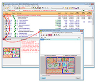
New buttons have been added in the Graphical information of the concept dialogue box (select the code of a concept or the icon representing the concept in the Decomposition tree window > press the graphical information of the concept icon located in the top left-hand corner of the screen). These buttons are used to move one place up or down from the selected element and so help users to organise the graphical information that a concept (chapter, job unit...) may have.
 Improved concept image management in report templates
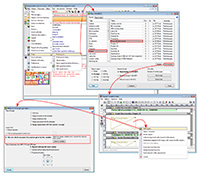
A new option has been implemented: The one which occupies the position given by the variable, located in the Attributes of image type object dialogue box of the Report template editor (File > Print > Print report > Select a template with graphical concepts –for example Price justification annex in the Images group- > Edit template button > click on a drawing type object using the right mouse button and select, from the menu that appears, Edit object).
This option allows for the selection of a whole variable (which must previously be created – Data menu of the Reports template editor > Template variables), that will contain the index of the drawing to be printed. The value of the variable is evaluated before proceeding to print the zone containing the drawing type object, so the image that occupies the order number to which the variable refers to can be printed.
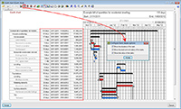 Improved editing of the Gantt chart
The button, Configure Gantt chart display options, has been added in the Gantt chart dialogue box (Show > Gantt chart). This button opens a dialogue box with the same name, where users can activate or deactivate the following columns: duration of the task, start and end dates of the task and value of the tasks, so they can be viewed in the chart.
Document styles
Font sizes 6 and 7 have been included for all CYPE programs for which document styles are available.
Tel. USA (+1) 202 569 8902 // UK (+44) 20 3608 1448 // Spain (+34) 965 922 550 - Fax (+34) 965 124 950