
(5th July 2013)
![]()
- Code implementation and improvements in its application
- CYPECAD
- Interaction of the structure with the construction elements
- Consideration of floors below ground level in the dynamic seismic analysis
- Consideration of the Integrated 3D structures in the dynamic seismic analysis
- Advanced beam editor. Horizontal openings in beams
- Geometry of the openings and types of beams they may be applied to
- Conditions of the position and dimensions of the openings
- Introducing the openings and defining their reinforcement
- U.L.S. checks of the openings
- Reinforcement details of the openings in drawings
- Configuration options for reinforcement layers
New modules
Interaction of the structure with the construction elements
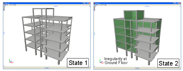
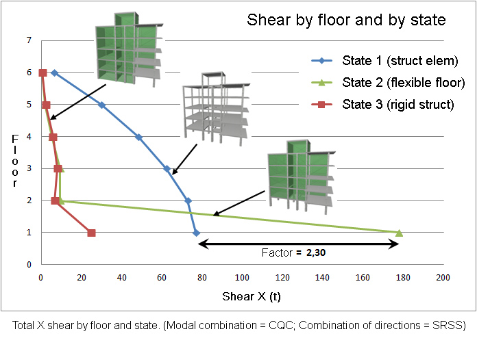
CYPECAD contains a software tool which allows for a dynamic analysis to be carried out on buildings with seismic loads acting upon them, which includes the effects of the non-structural construction elements used in the façades and partitions of the building, and considers various behavioural models of the building corresponding to different situations or states of these elements.
The façades and partitions of the building are considered as being “non-structural” elements, however, during an earthquake, they do provide stiffness to the structure, hence modifying the distribution and magnitude of the forces caused by the seismic action For example, when there is a non-uniform distribution between floors of the stiffness associated with the partitions, the horizontal forces have a greater impact on the columns belonging to the floors with less stiffness, producing shear forces of a high magnitude in the columns. If these have not been designed accordingly, the forces can cause a fragile fracture, endangering the stability of the building, even leading to its collapse.
This is the case of buildings, whose ground floor is destined to be used as retail precincts, and are, generally, irregularly stiff, causing them to be weaker at that floor. The difference in stiffness is due to the height of that floor usually being higher than that of the other floors, and that, due to the use of the floor, is an open floor. Even if the floor below were to have a similar stiffness to that of those above, during the first instants of the earthquake, the partitions of the lower parts of the building fracture, causing an abrupt change in the stiffness, and therefore, an irregularity similar to that described previously. Hence, the stiffness provided by the different non-structural elements can change during the seismic action, due to the cracks and fractures which appear successively.
This module has been developed by CYPE, with the collaboration of the Centro Internacional de Métodos Numéricos en Ingeniería (CIMNE) of the Universidad Politécnica de Cataluña (UPC), financed by the Centro para el Desarrollo Tecnológico Industrial (CDTI) and co-financed by the European Regional Development Fund (ERDF).
There are currently no software tools available on the market for the structural analysis of buildings which integrate the possibility of considering, in a simple manner, the façades and partitions, even though it has been proved that they directly affect the stability, stiffness and safety of the building during an earthquake. Since this CYPECAD module does integrate them, keeping the computation periods within an admissible period, their integration in the building projects will increase their quality and the safety of their occupants, allowing for unfortunate losses, both material and human, to be avoided after an earthquake.
More information can be found on the Interaction of the structure with the construction elements webpage.
Code implementation and improvements in its application
Concrete code
BAEL 91 (R-99) (France)
Règles techniques de conception et de calcul de ouvrages et constructions en béton armé suivant la method des états limites.
This code was implemented in CYPE programs in the 2009.1.a version. In the 2013.b version, a group of codes were included which allowed for the Advanced column editor of CYPECAD to be used (which, besides permitting users to use the advanced column editor, also allowed for the Detailed Ultimate Limit State reports and automatic reinforcement tables to be generated).
Now, in the 2014.a version, the following improvements have been implemented when using the French BEL 91 (R-99) concrete code:
- Use of the Advanced beam editor of CYPECAD, which includes amongst other features:
- Detailed U.L.S. and S.L.S. check reports for concrete beams (including torsion checks)
- U.L.S. and S.L.S. reports for steel beams
- Reinforcement area (required and effective) graphs
- Reinforcement bar bending diagrams and reinforcement detailing in the frame drawings
- And, in general, allows users to edit the resistant elements of the frame graphically, easily, quickly and comfortably (reinforcement, steel sections, lattices, shear studs, etc.)
- By combining the use of the BAEL 91 (R-99) with the following seismic codes, the advanced beam and column editors of CYPECAD can also be used:
- PS 92 (France)
Règles de Construction Parasismique – Règles PS applicable aux bâtiments – PS 92.
- PS 92 (version révisée 2010) (France)
Règles de Construction Parasismique – Règles PS applicable aux bâtiments – PS 92 (version révisée 2010).
- RPA 99/v 2003 (Algeria)
Règles Parasismiques Algériennes RPA 99 / VERSION 2003.
- RPS 2000 (Morocco)
Règlement de Construction Parasismique.
- RPS 2011 (Morocco)
Règlement de Construction Parasismique (version révisée 2011).
Additionally, the U.L.S. reports for columns and beams that are generated by the advanced beam and column editors, include reinforcement ductility criteria and the capacity design criteria for seismic design (bending and shear for the seismic design of concrete supports, and capacity design criteria for shear for the seismic design of concrete beams) indicated in each of the aforementioned codes.
Cold-formed steel code
SANS 10162-2:2011 (South Africa)
South African National Standard. The structural use of steel. Part 2: Cold-formed steel structures.
Implemented in CYPECAD, Metal 3D and Portal frame generator for basic cold-formed sections.
Loads on structures. Seismic loads
PS 92 (France); PS 92 (version révisée 2010) (France); RPA 99/v 2003 (Algeria); RPS 2000 (Morocco); RPS 2011 (Morocco)
When analysing with CYPECAD, if users select the French BAEL 91 (R-99) code and combine it with any of the indicated seismic loads, the program will take into account the reinforcement ductility criteria and the capacity design criteria for seismic design of the selected seismic code. These criteria are justified in the detailed Ultimate Limit State reports generated by the Advanced column and beam editors of CYPECAD.
More information on the combined use of the BAEL 91 (R-99) code with the indicated seismic codes can be found in the BAEL 91 (R-99) (France) section.
Loads on structures. Wind loads
СНиП 2.01.07-85* (Russia)
НАГРУЗКИ И ВОЗДЕЙСТВИЯ. СНиП 2.01.07-85*. 11 Воздействия ветра
Loads and effects. SNIP 2.01.07-85*.11 The effects of the wind
Implemented in CYPECAD.
CYPECAD
Interaction of the structure with the construction elements
CYPECAD contains a software tool which allows for a dynamic analysis to be carried out on buildings with seismic loads acting upon them, which includes the effects of the non-structural construction elements used in the façades and partitions of the building, and considers various behavioural models of the building corresponding to different situations or states of these elements.
More information can be found in the New modules section on this webpage.
 Consideration of floors below ground level in the dynamic seismic analysis
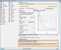
A new section, Degrees of freedom which intervene in the analysis, has been implemented in the seismic parameters dialogue box of each dynamic seismic analysis code – modal spectral analysis – (Job > General data > Select with seismic loading option > select seismic code).
Users are also informed here of the option which performs the same operation for the Integrated 3D structures of CYPECAD.
Consideration of the Integrated 3D structures in the dynamic seismic analysis
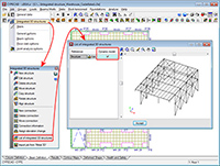
The option to activate or deactivate the possibility of considering the Integrated 3D structures in the dynamic seismic analysis has been implemented. This option is independent for each of the Integrated 3D structures contained in the same CYPECAD job and can be selected in the List of integrated 3D structures dialogue box
Advanced beam editor. Horizontal openings in beams
Geometry of the openings and types of beams they may be applied to
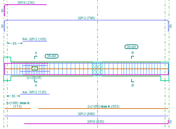
As of the 2014.a version, the Advanced beam editor of CYPECAD and Continuous beams allow for horizontal or circular openings to be introduced in reinforced concrete beams of constant or variable depth, of the following types:
- Dropped, rectangular beams (without lattice)
- Dropped “L” or “T” beams (without lattice)
Conditions of the position and dimensions of the openings
These openings are not considered during the analysis phase, and so, both their position and dimensions should remain restricted so that the efforts obtained may be considered valid. The limitations imposed by the program are the following:
- The height of the horizontal opening must be less than one third of the depth of the beam.
- The length of the horizontal opening must be less than the depth of the beam.
- The position of the horizontal opening must guarantee that the cover is respected in all the faces of the opening, and in the top and bottom surfaces of the beam.
- The free distance between consecutive horizontal openings must be greater than two times the depth of the beam.
- The free distance between a horizontal opening and the supporting side of the beam must be greater than half of its depth.
- No horizontal openings may be introduced in the confinement zones established by the seismic code.
The interaction between the reinforcement of the openings and the rest of the reinforcement introduced by users is completely automatic. When users introduce an opening, the program cuts the skin reinforcement bar at the opening, reorganises the stirrups on which the opening lies, and, if it is displaced, the reinforcement of the frame is modified in accordance. The program checks that the horizontal openings only cut the skin reinforcement bars. If this is not the case, an error message is displayed.
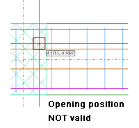
The conditions under which an opening is considered to be correctly defined may vary along the length of the frame (for example, if another opening is introduced very close to it, the stirrups of both openings could overlap, which would generate an undefined situation). If an opening cannot be processed, it is marked with a red dot and an error message is displayed when the mouse cursor is placed over it; and its effects on the previously introduced reinforcement disappear until the opening is deleted or the error is resolved.
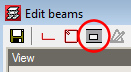 The options to define the openings are located in the Openings floating menu, which can be activated by selecting the
 ![]() button, that appears in the top buttons bar next to the transverse reinforcement edition option.
button, that appears in the top buttons bar next to the transverse reinforcement edition option.
Introducing the openings and defining their reinforcement
The Openings floating menu contains five options:
-
 New opening
Three steps must be followed to introduce a new opening:
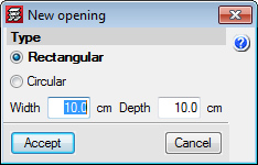
- Select the type of opening and its dimensions
Once the New opening button () is selected, the New opening dialogue appears on screen, in which the type of opening (Rectangular or Circular) and its dimensions are defined.
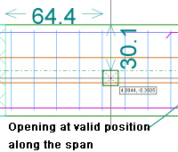
- Confirmation of the position of the opening on the span
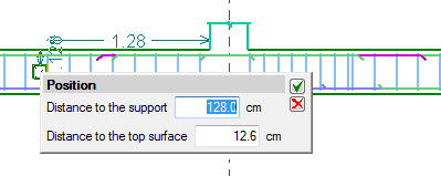
Once the dimensions of the opening have been introduced, users select the position (using the mouse cursor) on the frame at which it is to be introduced. During this process, the program displays the opening with the shape and size that have been specified, and its coordinates, which depend on the position of the mouse cursor. Unless the opening cannot be introduced at the current position of the cursor, two coordinates will always be displayed:
- The distance with respect to the support
- The distance with respect to the top face of the beam
To confirm the position of the opening, simply click on the left mouse button so a panel appears allowing for the numerical position of the opening to be defined.
- Defining the reinforcement of the opening
The reinforcement is composed, for both rectangular and circular openings, of:
- Top reinforcement
- Bottom reinforcement
- Stirrups applied to the corresponding zone of the opening
- Anchorage of bars that are cut due to the interaction with the opening (only affects skin reinforcement bars).
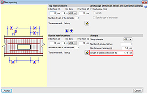

The Length of lateral confinement, which is required in the dialogue box in which the reinforcement of the opening is defined, refers to the zones at either side of the opening. The same stirrup arrangement is used in both zones defined by the lateral confinement length as before the opening was introduced, but with the stirrup diameter and spacing defined for the opening. These zones are used to guarantee the shear is transmitted correctly between the zone of the beam without an opening and the zone with.
Two independent stirrup arrangements can be defined for the parts above and below the opening, and the template of the opening (indicates the points which can tie the stirrups or cross-ties) must be compatible with the base reinforcement template of the span in which it is located (to avoid there being loose stirrups). The number of reinforcement bars of the opening must be greater than or equal to the number of reinforcement bars of the template to guarantee there is a bar at all the positions at which the stirrups are held.
 Edit opening
This option displays the same dialogue in which the reinforcement of the opening has been defined using the New opening () option.
The reinforcement of the opening can also be edited from:
- The edition of the longitudinal reinforcement of the frame
( button on the top bar of the beam editor > Edit). This way a panel is displayed which allows users to edit the reinforcement of the opening.
- The edition of the transverse reinforcement of the frame
( button on the top bar of the beam editor > Edit). Allows users to edit the transverse reinforcement of the opening, the additional reinforcement and anchorage.
 Edit opening and assign
Allows users to match the type of opening and their reinforcement to several openings. First of all, users must select the opening which is to be taken as the source opening (which will allow for any parameters to be edited) and then, select the openings to be matched. This selection can be carried out one-by-one, or using a capture window. Those which are the same are displayed in orange and those that are different in yellow.
 Move opening
Allows users to displace the opening within the same span. Simply select the opening and drag it to its new position. When the opening is placed in its new position, the program applies the same considerations as when a new opening is introduced.
 Delete opening
Users can delete the selected opening or openings. Multiple openings can be selected for deletion (using a capture window), or deleted individually.
U.L.S. checks of the openings
The U.L.S. checks of the introduced openings can be consulted using the existing options in the beam editor, ![]() (U.L.S. checks at the worst case point) and
(U.L.S. checks at the worst case point) and ![]() (U.L.S. checks at a point) buttons. In the case of the worst case point, all the checks of the openings the beam may have are added to the checks of the beam. When consulting the checks at a point, the opening can be selected directly.
(U.L.S. checks at a point) buttons. In the case of the worst case point, all the checks of the openings the beam may have are added to the checks of the beam. When consulting the checks at a point, the opening can be selected directly.
When checking a beam with openings, worst case checks of the beam may appear in the zone in which the opening is situated because the program considers that the zone of the opening should meet the requirements of the section with the opening as well as the section without it.
An element filter has been implemented to help when consulting the checks of the openings using the worst case point option (![]() ).
).
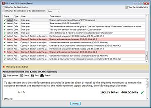
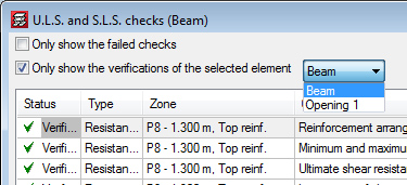
For beams without openings, the panel has exactly the same appearance as it did before.
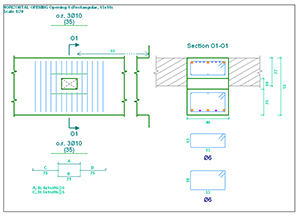
Reinforcement details of the openings in drawings
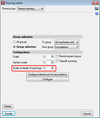
If a frame contains openings, the details of the opening are automatically generated integrated within the details of each frame. The scale of the detail of the opening can be configured by users.
 Configuration options for reinforcement layers
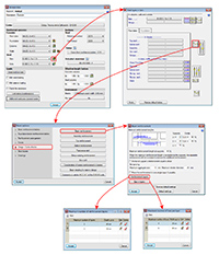
Two new options: Reinforcement layers and Bars in layers, have been implemented in the Beam reinforcement dialogue box (Job > General data > By position button > Beam options > Design/ Code checks > Beam reinforcement – see image). These options allow users to distribute the beam reinforcement in different layers.
- Reinforcement layers
Users can create a table indicating the maximum number of layers depending on the depth of the beam.
- Bars in layers
Users can create a table indicating the maximum number of bars depending on the width of the beam.
CYPECAD MEP
Energy certification for Italy
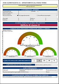 The 2014.a version of CYPECAD MEP for Italy can generate a document containing the national Energy performance certificate model (Attestato di certificazione energetica) (Studio termico > File > Stampare > Relazioni del progetto > Attestato di certificazione energetica).
Solar thermal energy installation for the production of hot sanitary water included for more countries
As of previous versions, CYPECAD MEP allows for user to design a solar thermal energy installation for individual or collective use, for the production of hot sanitary water for Spain and Portugal. As of the 2014.a version, this installation can also be designed for the following countries:
- Angola
- Argentina
- Brazil
- Cape Verde
- Chile
- Colombia
- Mexico
- Mozambique
- Peru
 To do so, the design of the installation has been adapted so it is valid for any latitude.
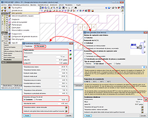
For all the countries for which the solar thermal design is available, the climate data of the location of the building can now be edited from the Solar thermal tab (including the monthly values of the External temperature and Monthly daily average solar irradiation over horizontal surface). In previous versions (for Spain and Portugal), the climate data could only be edited from the Thermal study and Air conditioning tabs.
Tel. USA (+1) 202 569 8902 // UK (+44) 20 3608 1448 // Spain (+34) 965 922 550 - Fax (+34) 965 124 950