- CYPE Architecture
- Open BIM Layout
- StruBIM Steel / CYPE Connect
- StruBIM Steel
- Quantities reports
- Assign material
- Assign insertion point
- Align section to plane
- Invert the direction of the X axis
- Symmetry
- Transparent visibility of tags
- Information texts with the weight of parts and assemblies
- Information texts with the status of connections
- Automatic saving options
- Update of forces when updating the BIM model
- Accessories
- CYPELEC Core
- CYPELEC Electrical Mechanisms
- Applications with a "Bill of quantities" tab
CYPE Architecture
Sketch groups
The program has two new features for grouping or ungrouping drawing elements in the “Sketch” tab. These features can be accessed from the “Sketch” tab in the “Drawing elements” section.
Sketch groups allow us to group lines and surface areas, isolating them from the rest of the elements, with the aim of making it easier to handle sets of drawing elements (move, copy, rotate, symmetries, etc.). The groups also isolate the elements they contain from the rest of the drawing, thus preventing them from overlapping with each other.
The “Sketch” tools interact in the following way with the groups:
- Move, Copy, Rotate, Scale and Symmetry will affect the whole group.
- Extrude will affect the surface areas by adding extruded elements to the group.
- Invert, Edit, Assign colour and Assign label will affect the surface areas, adding the properties to the group.
- Offset will affect the surface areas but will not add the new offset elements to the group.
Each generated group is unique, modifying an element of a group will not affect copies of the same group. To learn how to create matching sets, see the new feature: “Sketch objects”.
Sketch objects
In the “Sketch” tab, the program has new features to create objects from drawing elements. These features can be accessed from the “Sketch” tab in the “Objects” section.
Sketch objects allow us to group lines, surface areas and groups, isolating them from the rest of the elements, with the aim of making it easier to handle sets of drawing elements (move, copy, rotate, symmetries, etc.). The objects also isolate the elements they contain from the rest of the drawing, thus preventing them from overlapping with each other.
When an object is created it is added to a local library, unlike sketch groups that do not have a library.
The library allows users to export and import objects for reuse.
Sketch objects are related to each other, so modifying one object will affect the copies of that object.
To modify an object, users must explode it, make the necessary modifications, and finally recreate the object with the same reference as the one they want to modify. This will overwrite the object in the library and therefore also all its copies.
The “Objects” section of the “Sketch” tab has the following features:
- Library
Allows objects to be imported and exported, and access to the object’s colours. - New
Creates a new object from lines, surface areas and groups. - Insert
Allows an object from the library to be inserted. - Explode
Allows an object to be broken down into lines, surface areas and groups. - Isolate
Creates a new object from an existing object that will no longer be related to the source object. - Add
Allows lines, surface areas or groups to be added to an existing object. The drawing elements will be added to all copied objects.
Objects interact with the Move, Copy, Delete, Rotate, Symmetry and Scale tools, but do not allow the surface areas’ properties to be modified or extruded. To do so, the object must be exploded and then created again.
Entering railings, ridges and valleys using a sketch line
The “Railing” and “Ridge/Valley” tools have a new entry mode: “Using a sketch line”. This entry mode allows users to select one or more sketch lines to enter these elements.
Improved “By surface area” sketch entry mode for glazed surfaces
The “By surface” sketch entry mode of the “Glazed surfaces” tool allows for the multiple selection of sketch surfaces (by dragging).
Open BIM Layout
New option: “Represent lines with print thickness”.
Within the “View on screen” options, the “Represent lines with print thickness” option has been implemented, which allows users to view vector scenes in two ways, with or without the print thickness.
StruBIM Steel / CYPE Connect
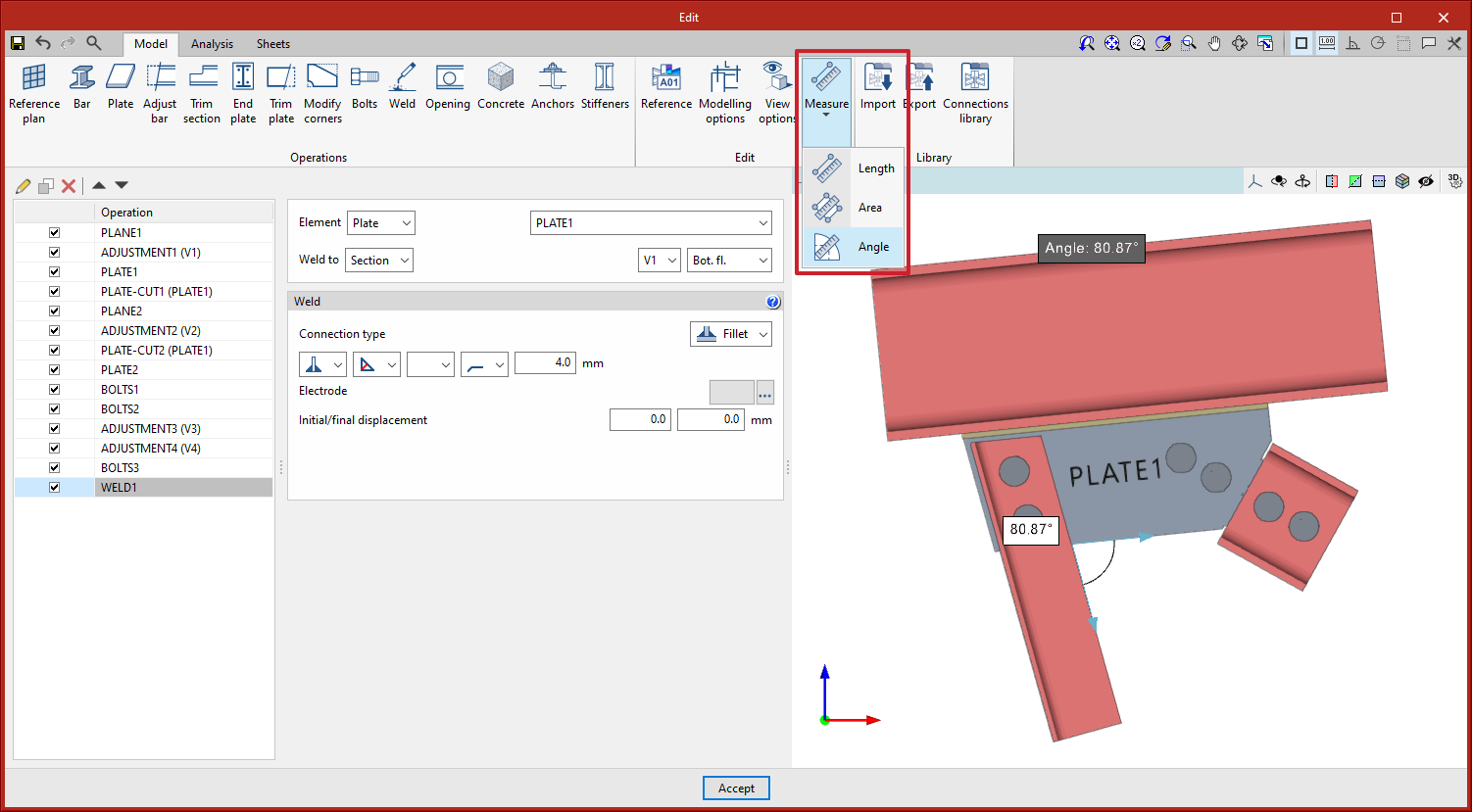
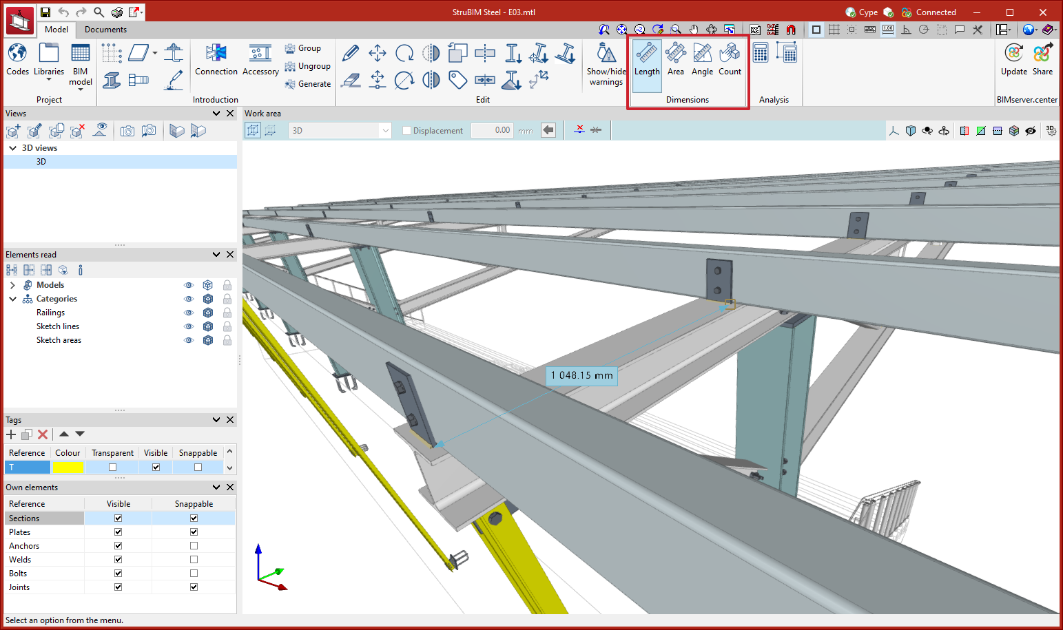
Measurement tools
Version 2023.f includes measurement tools for the work area. In the StruBIM Steel work area, these tools allow users to measure lengths, areas, and angles and to count elements. In CYPE Connect these tools allow users to measure lengths, areas and angles.
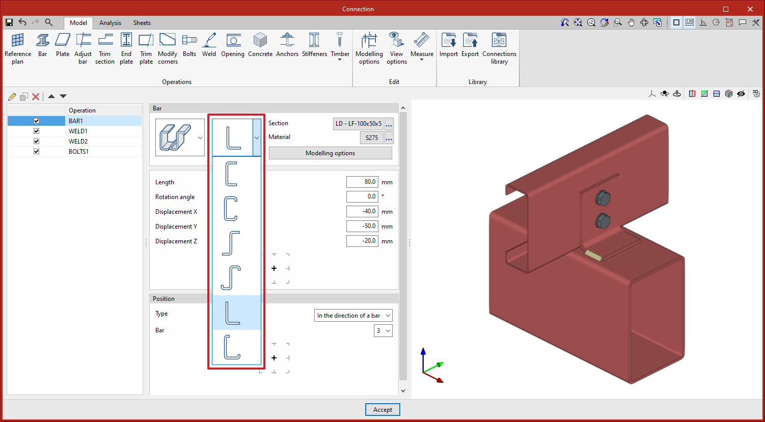
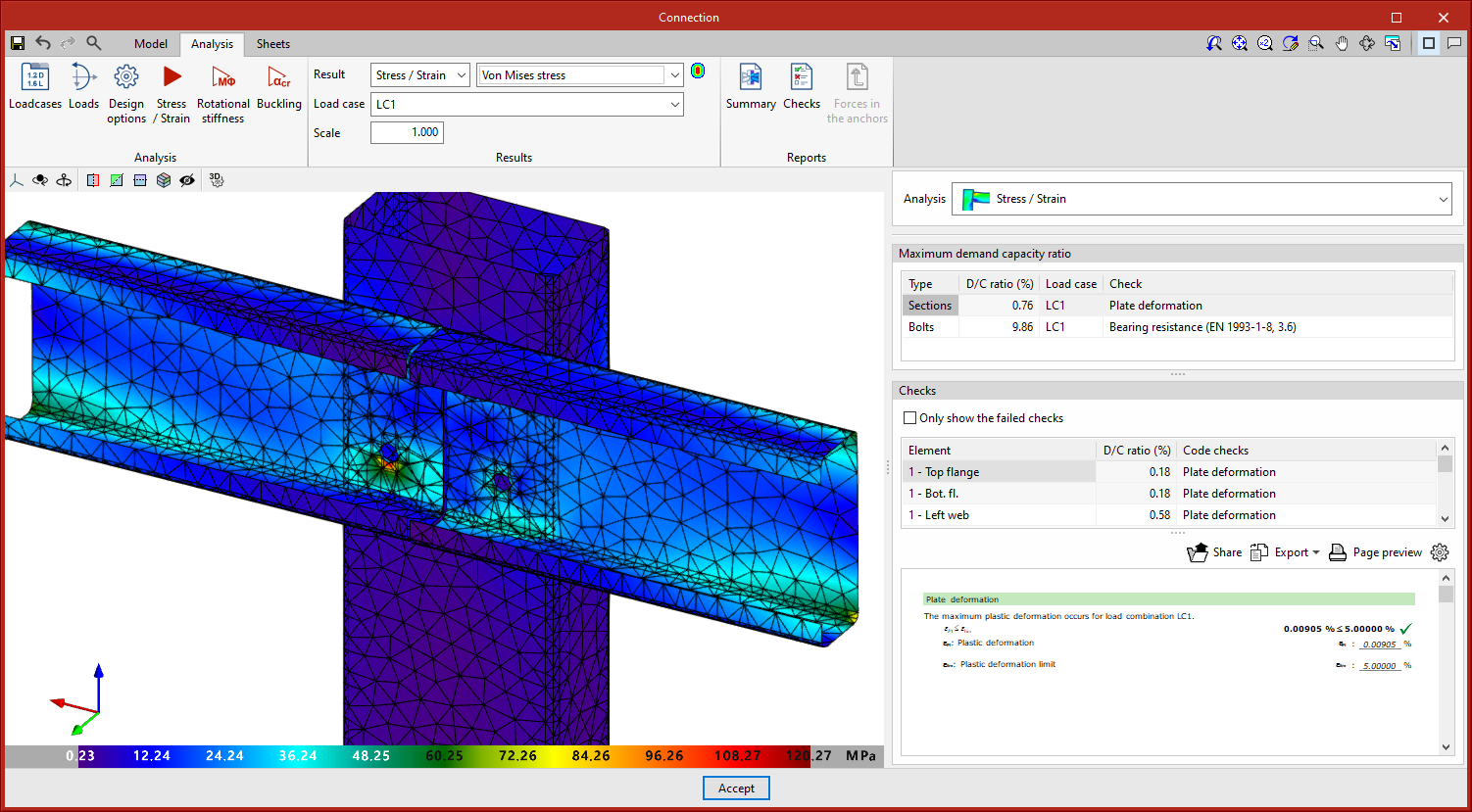
New types of cold-formed sections
In versions before 2023.f, the program could work with rectangular timber bars (CYPE Connect) and rolled steel I sections, C sections, angle sections, T sections, plates and rectangular hollow sections (CYPE Connect and StruBIM Steel). In version 2023.f, six new types of cold-formed sections have been implemented for both CYPE Connect and StruBIM Steel:
- U
- C
- Unstiffened Z
- Stiffened Z
- Unstiffened L
- Stiffened L
These sections are available both as the node’s own bars and as additional bars in the “Bar” operation.
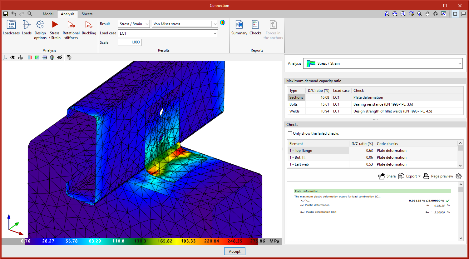
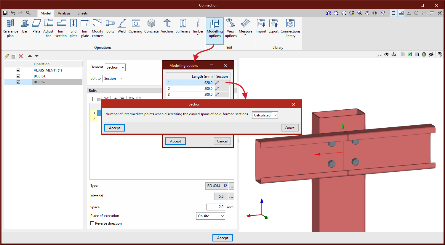
Discretisation of curved segments in sections
As of version 2023.f, curved segments of rectangular hollow sections or cold-formed sections can be discretised, distinguishing them from the adjacent straight segments. When discretising curved segments, the number of sides can be defined in “Modelling options” by selecting “Users” or the program can calculate an optimal number of sides by selecting “Calculated”.
StruBIM Steel
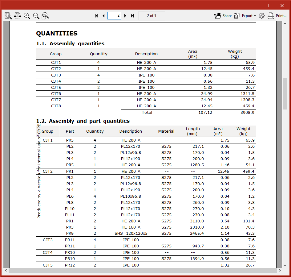
Quantities reports
Quantities reports of the elements of the structure have been implemented. The following tables are included in the implemented reports:
- Assembly quantities
- Assembly and part quantities
- Sections quantities
- Summary by type of section
- Plate quantities
- Bolt quantities
- Weld quantities
- Anchor quantities
These reports can be generated for the whole structure, for a selection of assemblies, or for a selection of parts.
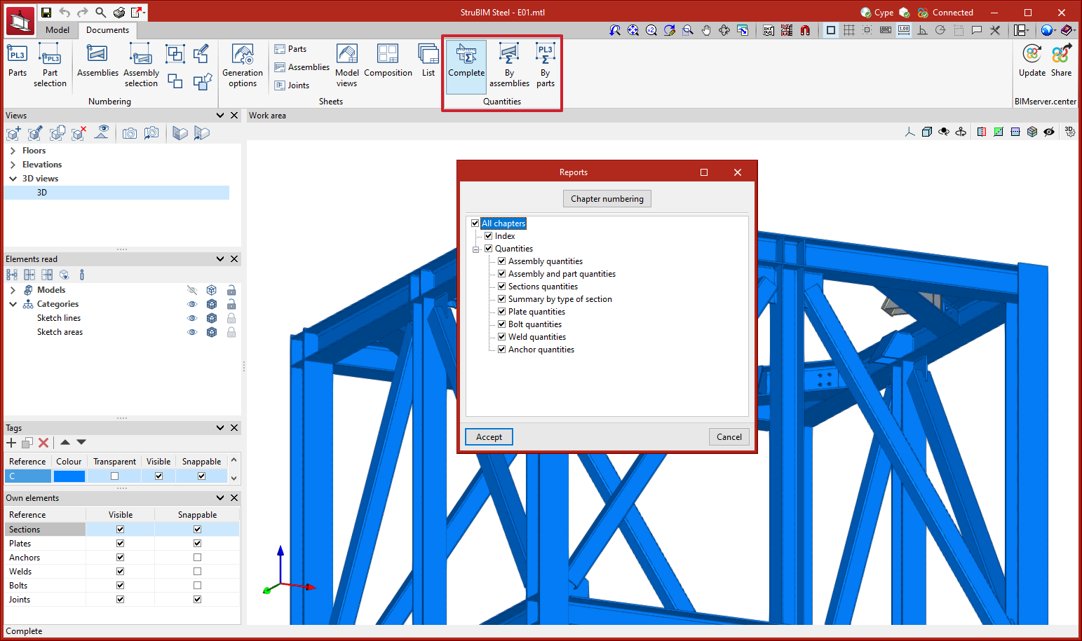
Assign material
A new tool, “Assign material”, can be found in the “Edit” menu. This tool allows the type of material to be assigned to a selection of sections.
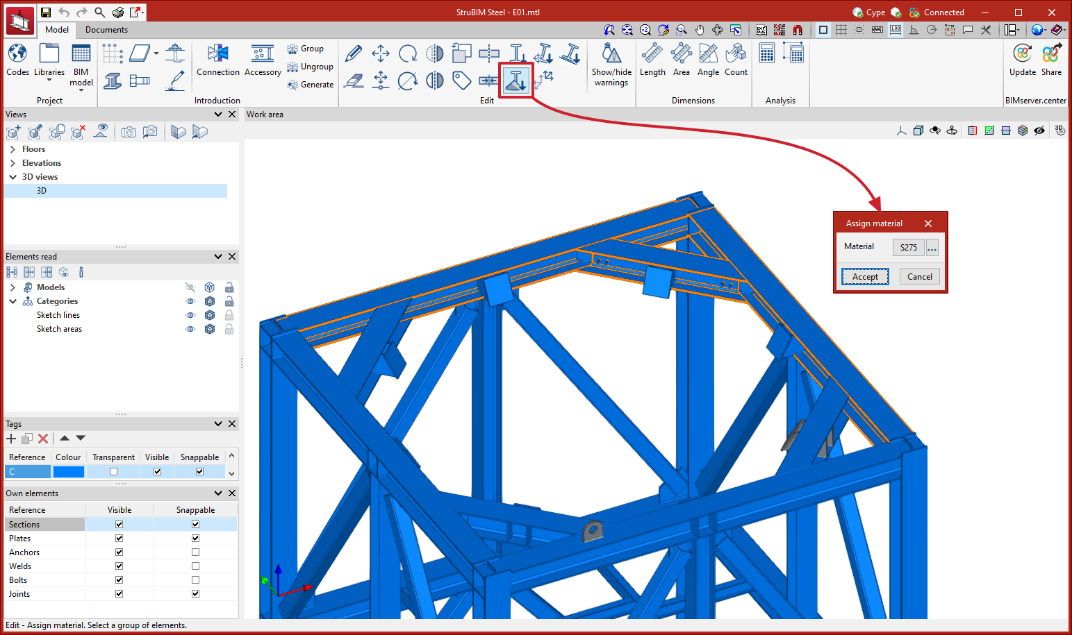
Assign insertion point
A new tool, “Assign insertion point” can be found in the “Edit” menu. This tool allows you to assign the levelling point, rotation angle and Y and Z displacements in local axes to a selection of sections.
Align section to plane
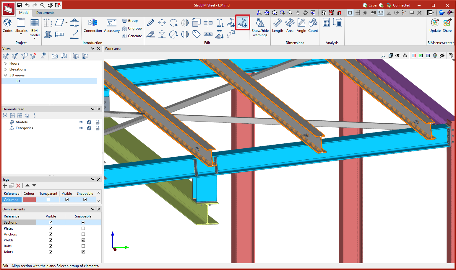
A new tool, “Align section to plane” can be found in the “Edit” menu. This tool allows users to align a selection of sections to a plane. For example, this could be useful when placing the purlins of a roof in line with the top face of the main beams.
After selecting the sections to be aligned, right-click the mouse and select the plane from the faces of the sections and plates in the model.
Invert the direction of the X axis
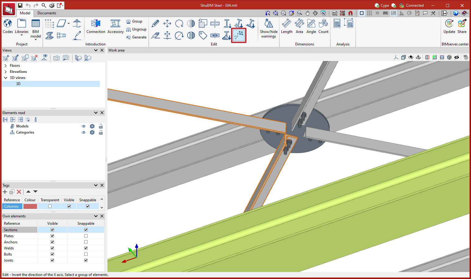
A new tool, “Invert the direction of the X axis” can be found in the “Edit” menu. Using this tool allows users to reverse the direction of the X-axis of a selection of sections.
Symmetry
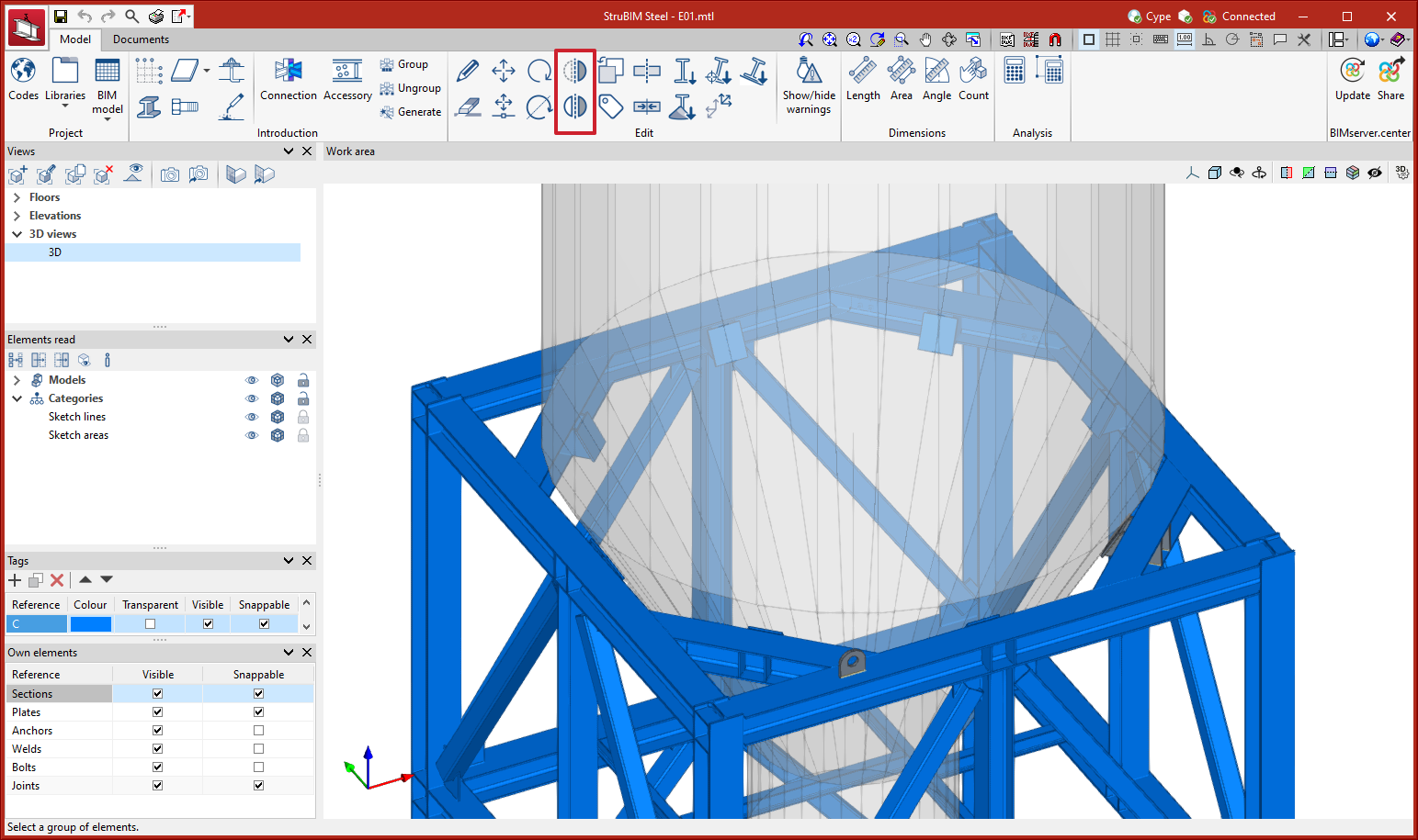
Two new tools have been implemented to carry out operations with symmetry:
- Symmetry (copy)
Copies a selection of elements with symmetry with respect to a vertical plane defined by two points. - Symmetry (move)
Moves a selection of elements with symmetry with respect to a vertical plane defined by two points.
Transparent visibility of tags
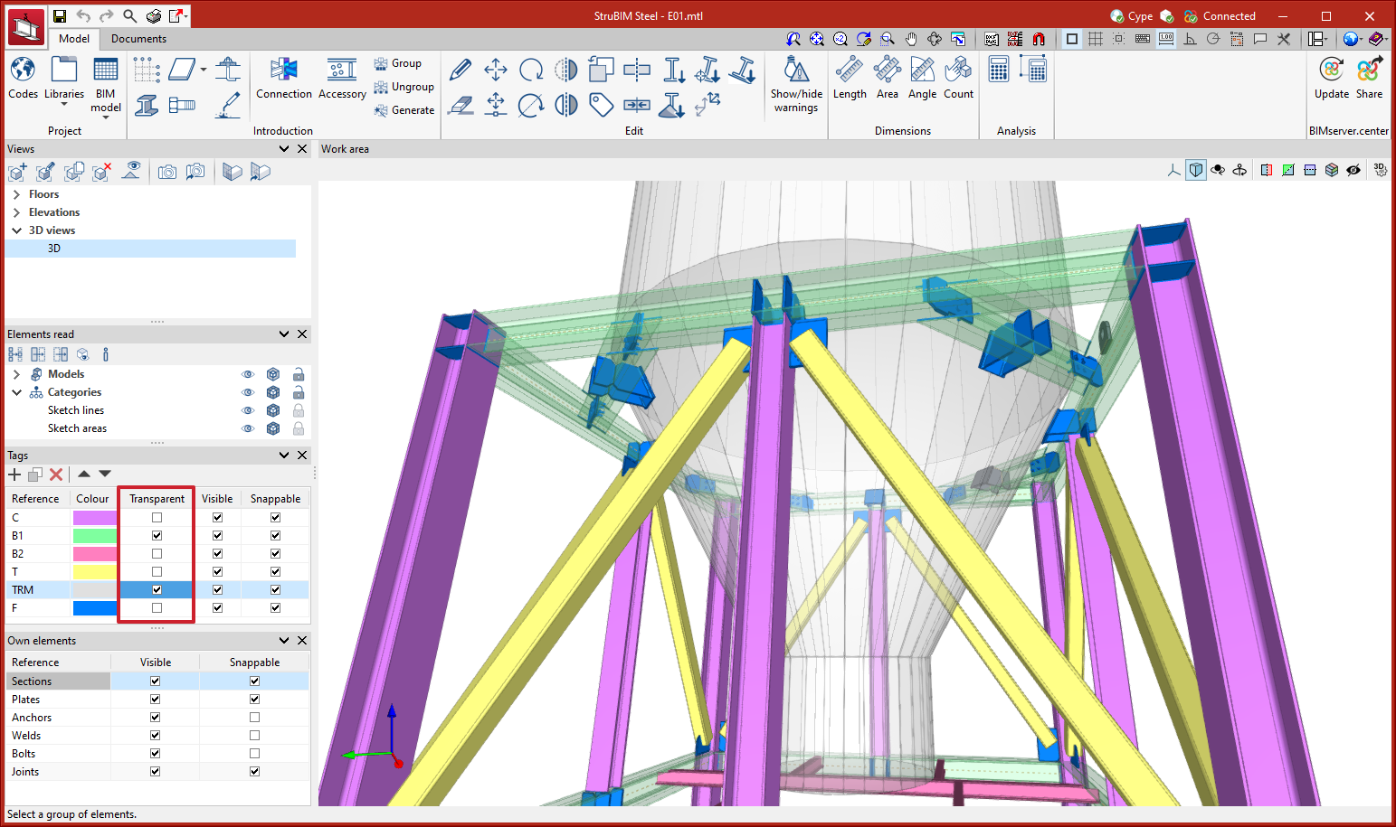
As of version 2023.f, the list of tags includes the new “Transparent” column. Elements will be shown as transparent when their tag is marked as “Transparent”.
Information texts with the weight of parts and assemblies
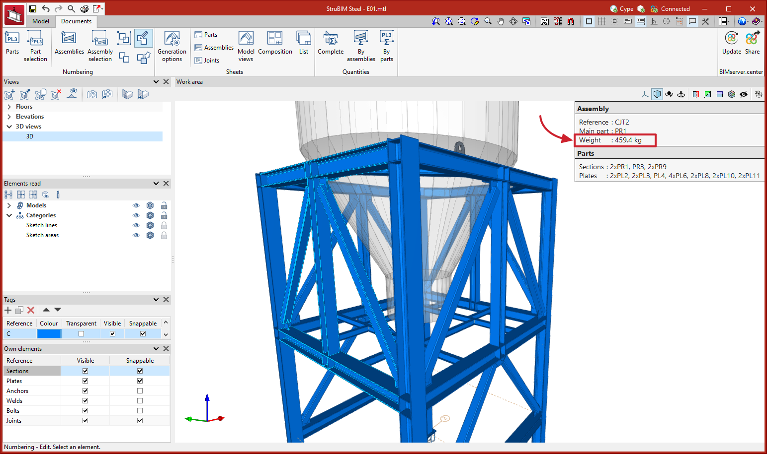
As of version 2023.f, information text panels will include the weight of the selected part or assembly.
Information texts with the status of connections
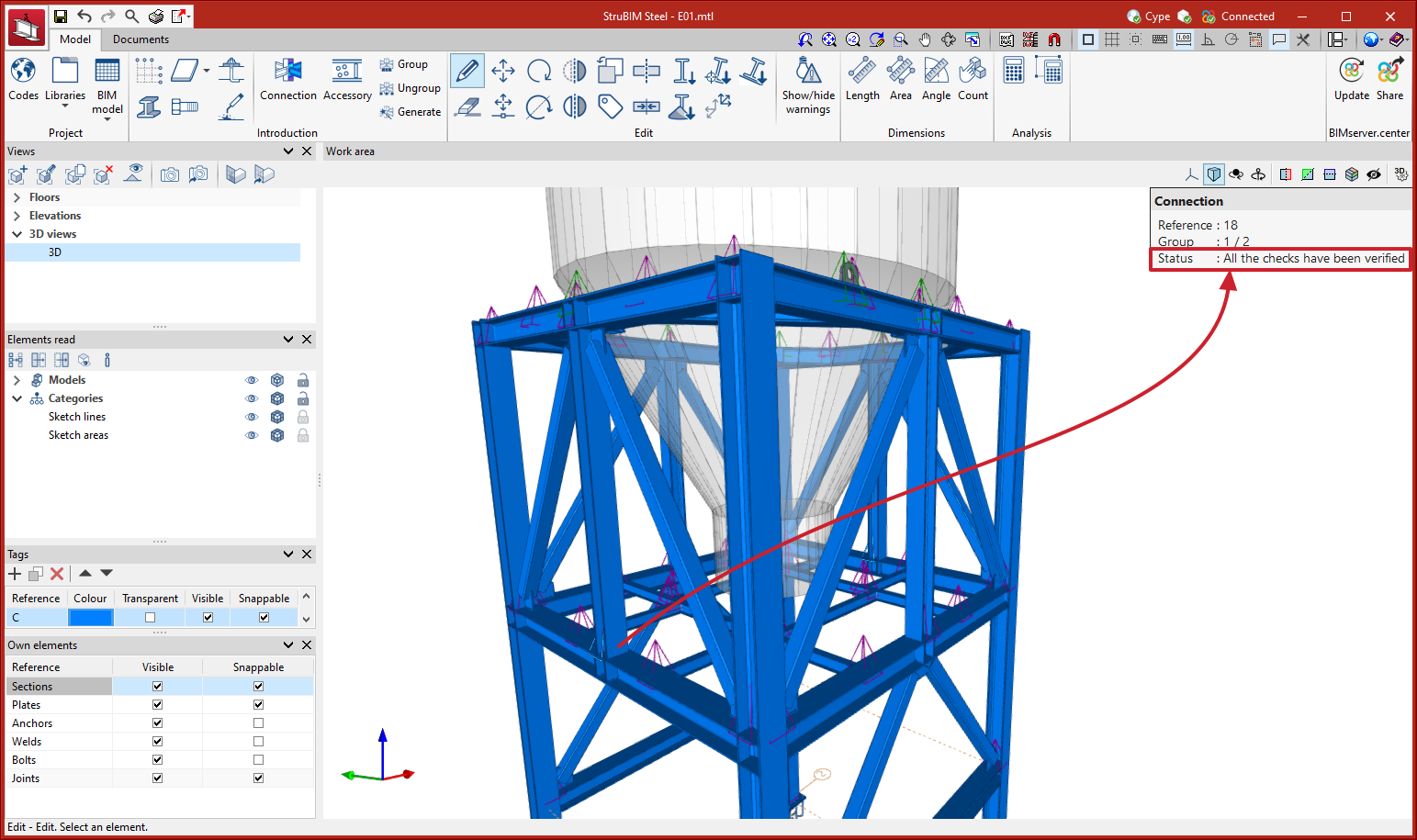
As of version 2023.f, information text windows of the connections will include the status.
Automatic saving options
“Automatic saving options” have been added to the “Configuration” menu. Using these options, users can configure when the job will be saved automatically.
Update of forces when updating the BIM model
As of version 2023.f, when the model is updated, the forces of the connections will be updated automatically. In previous versions, the bars of the model were updated but the forces were updated for each connection when the user clicked on “Generate from the BIM model”.
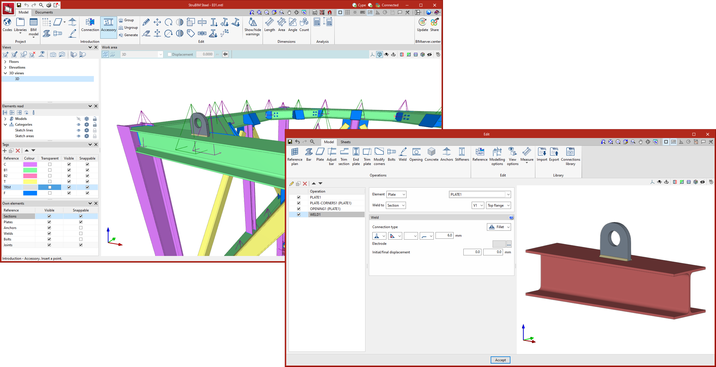
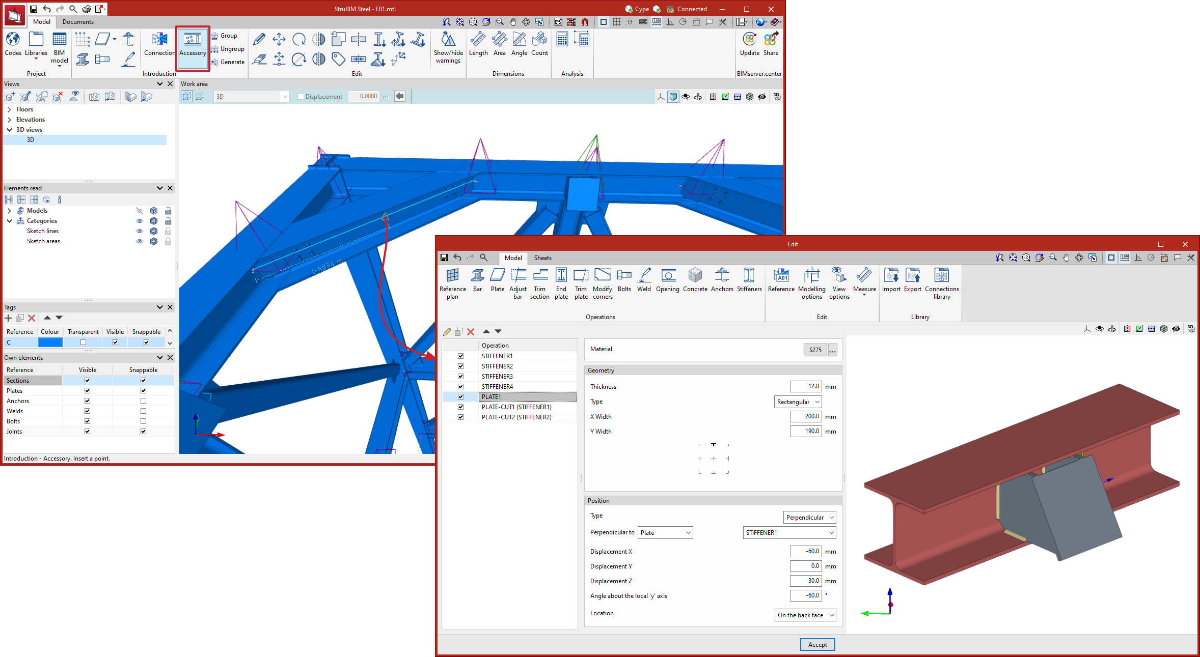
Accessories
In version 2023.f, the “Accessories” tool has been implemented. This tool allows sections to be edited in order to enter elements at intermediate points. The accessories work dialogue box is similar to the CYPE Connect connection editor. The purpose of this tool is to allow users to insert holes, openings, reinforcements, lifting lugs, etc. with the advantages offered by the connection editor. Just like the connections, the accessories can also be grouped together and saved in a library.
The symbol representing the accessories is a green pyramid, as opposed to the purple pyramid corresponding to the connections.
CYPELEC Core
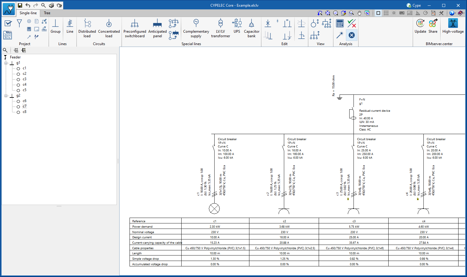
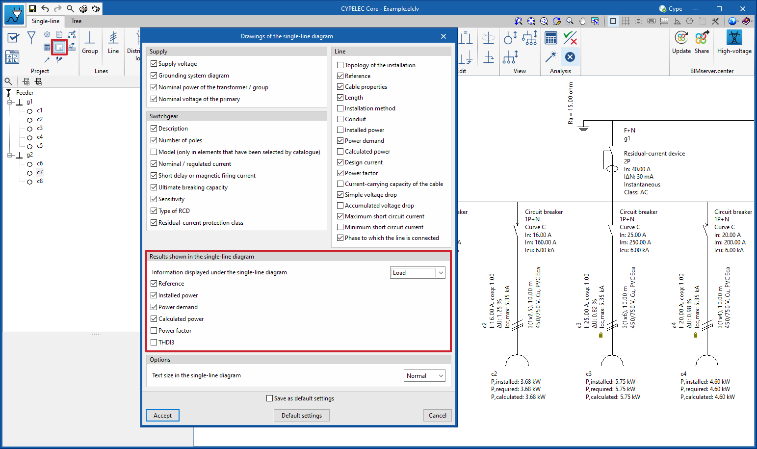
Improved information displayed in the single-line diagram
The information on the results displayed at the bottom of the single-line diagram has been improved. This information can be displayed under the electric load or shown in the form of a properties table.
The information shown is configurable and will depend on the selection indicated in the single-line diagram options.
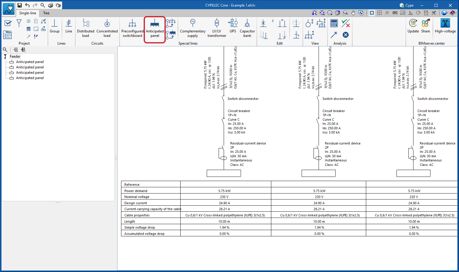
New line: Anticipated panel for power demand
A line called “Anticipated panel” has been added to represent a power supply line to a switchboard or sub-switchboard without having to indicate its internal circuits.
This line acts as a final line and is indicated in cases where users wish to provide a switchboard or sub-switchboard with its expected power demand but without developing its internal circuits.
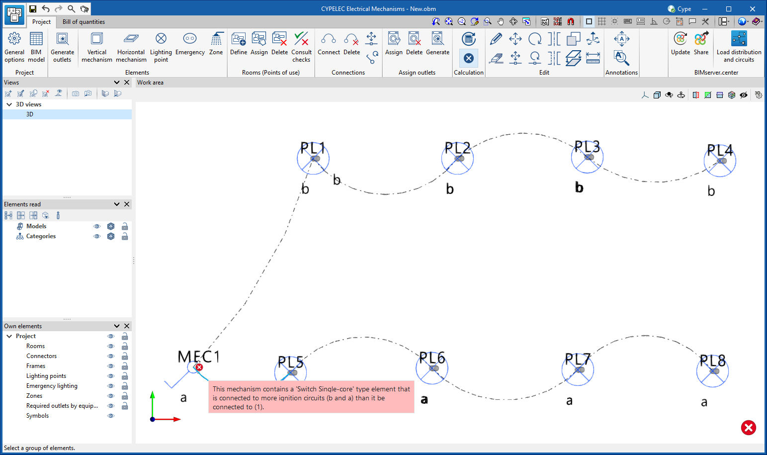
CYPELEC Electrical Mechanisms
Checking the connections between light mechanisms and lighting points (ignition circuits)
The checks related to the connectivity between the different types of switches (single, double, pushbuttons, light regulators, etc.) and lighting points have been improved.
The program will detect if the specified ignition circuits are correct and, if they are not, it will indicate the issue to be corrected.
Applications with a “Bill of quantities” tab
Character set in FIEBDC-3 export (.bc3)
As of version 2023.f, the character set to be used when exporting the bill of quantities in the standard FIEBDC-3 format (.bc3) can be selected from the “Bill of quantities” tab in the applications that have it. For this purpose, the “Character set” field has been included in the export configuration window and has three options:
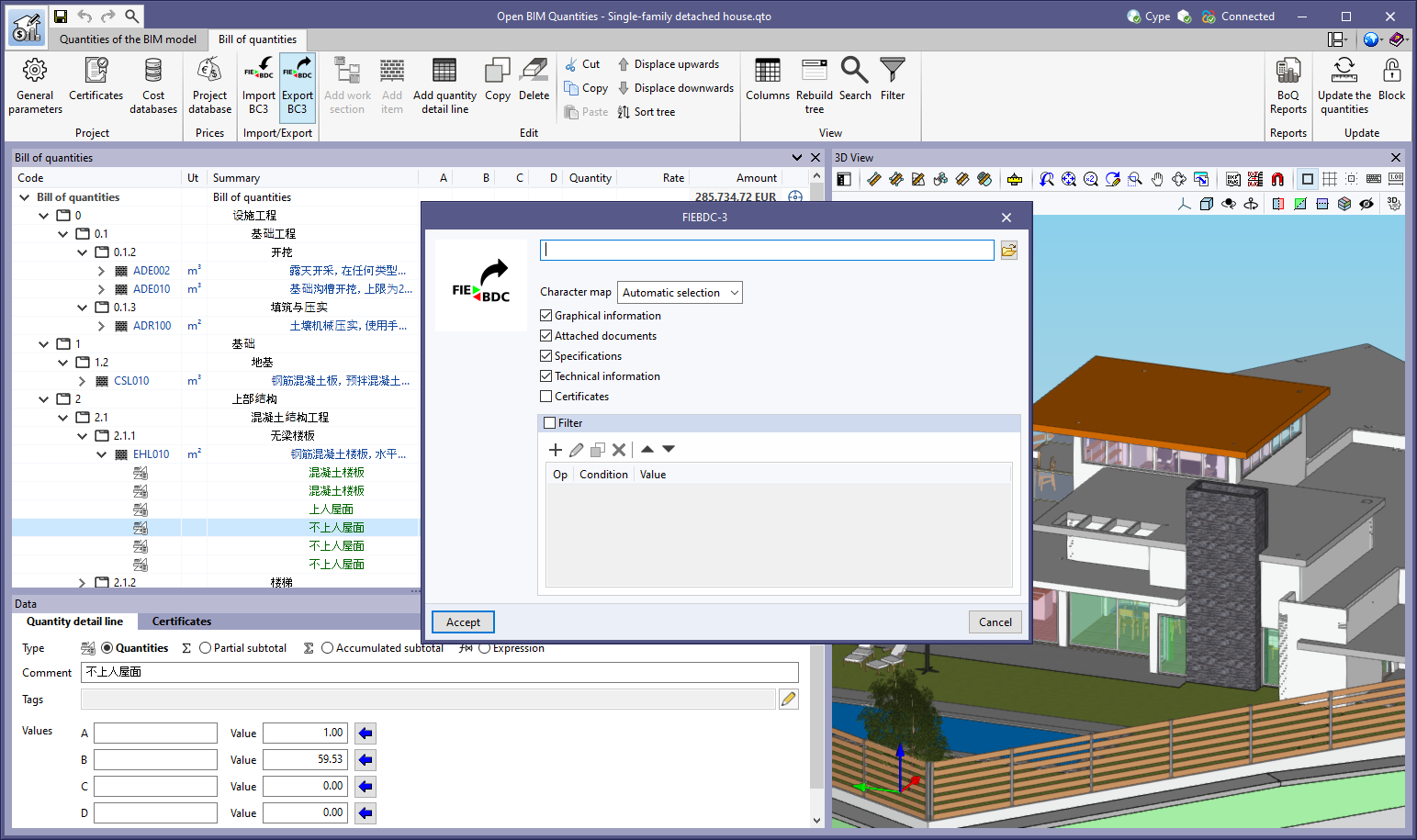
-
Automatic selection
The ANSI character set shall be used whenever possible. If the application detects characters that are not compatible with ANSI encoding, the UTF-8 character set shall be used. -
ANSI
This is the character set defined for Windows and the default character set used in previous versions. Not all Unicode characters can be represented by this encoding format. -
UTF-8
Through this standard encoding format (RFC 3629) all Unicode characters can be represented. However, the current FIEBDC-3 standard specification (3/2020) does not support UFT-8 encoding, so the ANSI character set should be used where possible (Automatic selection).
Thanks to the possibility of exporting and importing the bill of quantities in UTF-8 encoding, applications can now share bills of quantities that include Unicode characters. This establishes a fully multilingual environment for managing the project’s bills of quantities.
In the FIEBDC-3 standard, the character set is specified in the CHARACTER_SET field of the V record.
Return to the 2023 version download area
Tel. USA (+1) 202 569 8902 // UK (+44) 20 3608 1448 // Spain (+34) 965 922 550 - Fax (+34) 965 124 950