
NEW PROGRAMS AND MODULES
NEW FEATURES OF EXISTING PROGRAMS
- New features common to several programs
- Open BIM ISOVER
- Open BIM MOVAIR
- Open BIM PANASONIC
- Implementing regulations and improving their enforcement
- Open BIM add-in for Revit and cost estimates and plans from BIM models
- CYPE Architecture
- Types of architectural elements
- Improved label and label library functionality for Spain
- Show/Hide information
- Search by reference
- Copy between levels
- Automatic solution of roof intersections
- Cut by face
- Layer transparency
- New garden furniture
- Improved dwg/dxf and 3D snap interaction for doors and windows
- Open BIM Construction Systems
- Modifications in the descriptive report
- 3D file size reduction
- Optional density value in construction system layers
- Total thickness of the construction system
- "Edit" and "Delete" options for construction systems
- Construction systems pending assignment
- Assigning construction systems by type
- New example job
- Importing insulation products by Grupo Valero
- Invert introduction direction
- New fields for defining windows and skylights
- IFC Uploader
- Open BIM Layout
- Open BIM Analytical Model
- CYPECAD and CYPE 3D
- CYPECAD
- StruBIM Steel
- StruBIM Shear Walls
- CYPELEC PV Systems
- CYPETEL Schematics
- CYPEHVAC Radiant Floor
- CYPEPLUMBING Water Systems
- CYPETHERM Improvements Plus
- CYPETHERM LOADS
- CYPETHERM EPlus
- CYPETHERM programs with EnergyPlus engine (CYPETHERM EPlus, CYPETHERM FUJITSU)
- Arquimedes
- Open BIM Cost Estimator
- Open BIM Quantities and applications with the Bill of Quantities tab
- Open BIM Quantities
- "Search" tool in the "Quantities of the BIM model" tab
- View options of the BIM model
- Reading of the properties and quantities associated with the type
- Reading of complex quantities and properties of IFC files
- Item tags in measurement rules
- Spatial structure element properties
- Grouping of IFC entities by type
- Marking BIM model components in 3D view
- Text styles in the cost breakdown structure
- Properties and quantities filter
- Quick measurement rules
- Update of example jobs
- Return to the 2021 version download area
NEW PROGRAMS AND MODULES
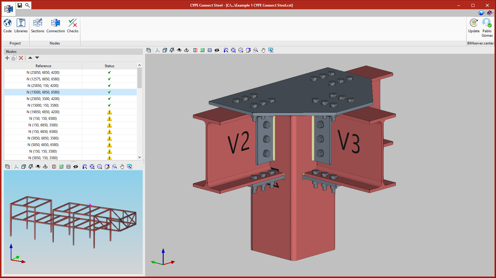
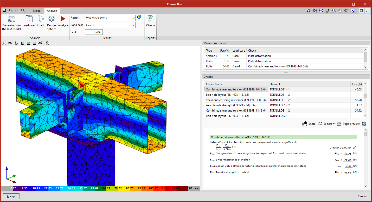
CYPE Connect Steel
CYPE Connect Steel is an application for the modelling and design analysis of steel structure connections using the finite element method. This application uses the OpenSees calculation engine.
CYPE Connect Steel imports steel structure nodes from the design models of BIM projects hosted on the BIMserver.center platform. As of version 2021.f, CYPECAD, CYPE 3D and StruBIM CYPE 3D users have the possibility of generating these design models in a BIM project, to which they export, along with other data, the forces in the nodes so that they can be used for designing connections by CYPE Connect Steel.
The program also offers users the chance to create nodes freely. Based on the sections used in the connection, users can model every component defining the connection (plates, bolts, welds, support sections, etc.) and carry out the analyses and checks.
CYPE Connect Steel also works as an integrated tool in StruBIM Steel. More information on how this works can be found in the 2021.f New features for StruBIM Steel.
In its first version, CYPE Connect Steel can design following EAE 2011 and Eurocode standards.
More information on CYPE Connect Steel.
CYPELEC Code Compliance
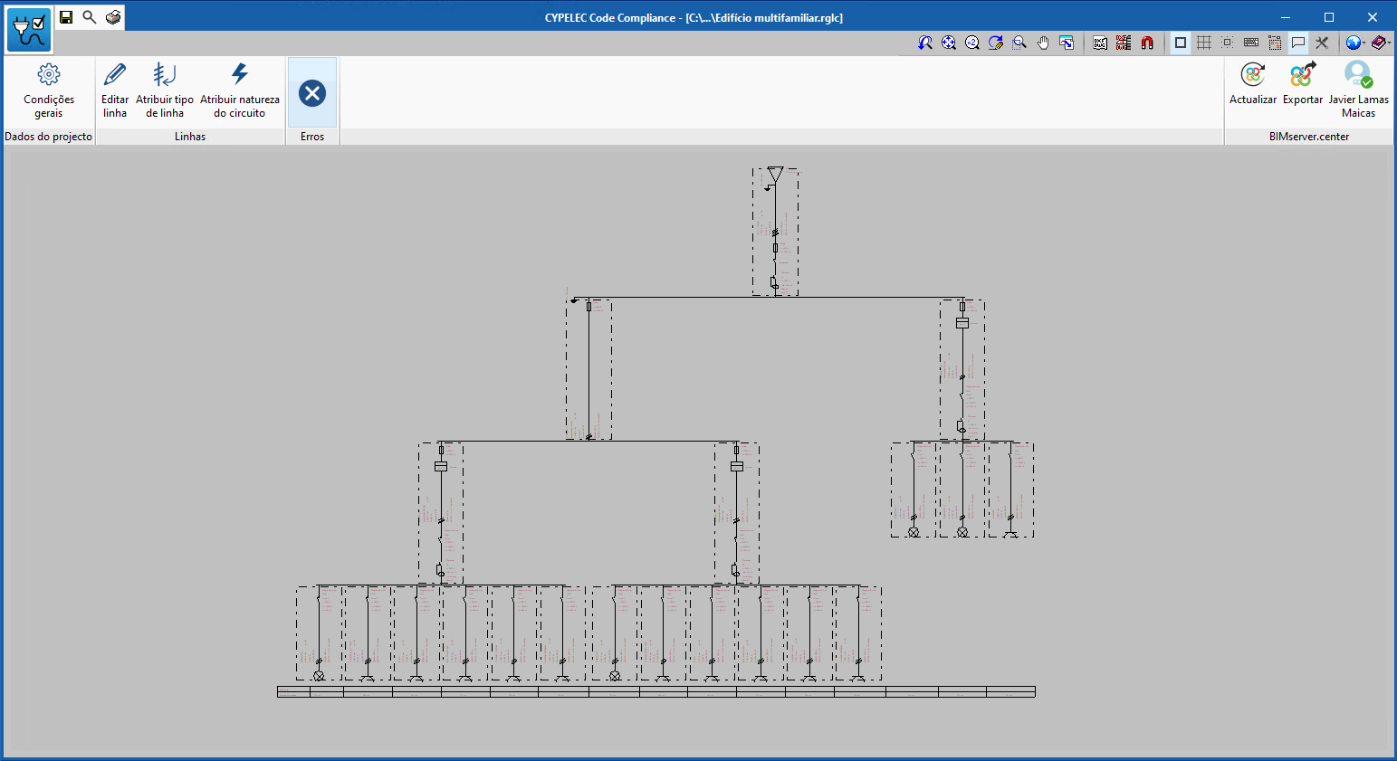
CYPELEC Code Compliance is an application designed by CYPE for carrying out checks on electrical lines according to Portuguese RTIEBT regulations.
It is integrated into the Open BIM workflow using the BIMserver.center platform.
CYPELEC Code Compliance carries out the checks for each of the electrical installation lines applying the Portuguese RTIEBT regulations. To do this, CYPELEC Code Compliance must be connected to a BIM project hosted on the BIMserver.center platform to which CYPELEC Core has previously exported the electrical installation analysis.
CYPELEC Code Compliance is installed in Portuguese only.
More information (in Portuguese).
NEW FEATURES OF EXISTING PROGRAMS
New features common to several programs
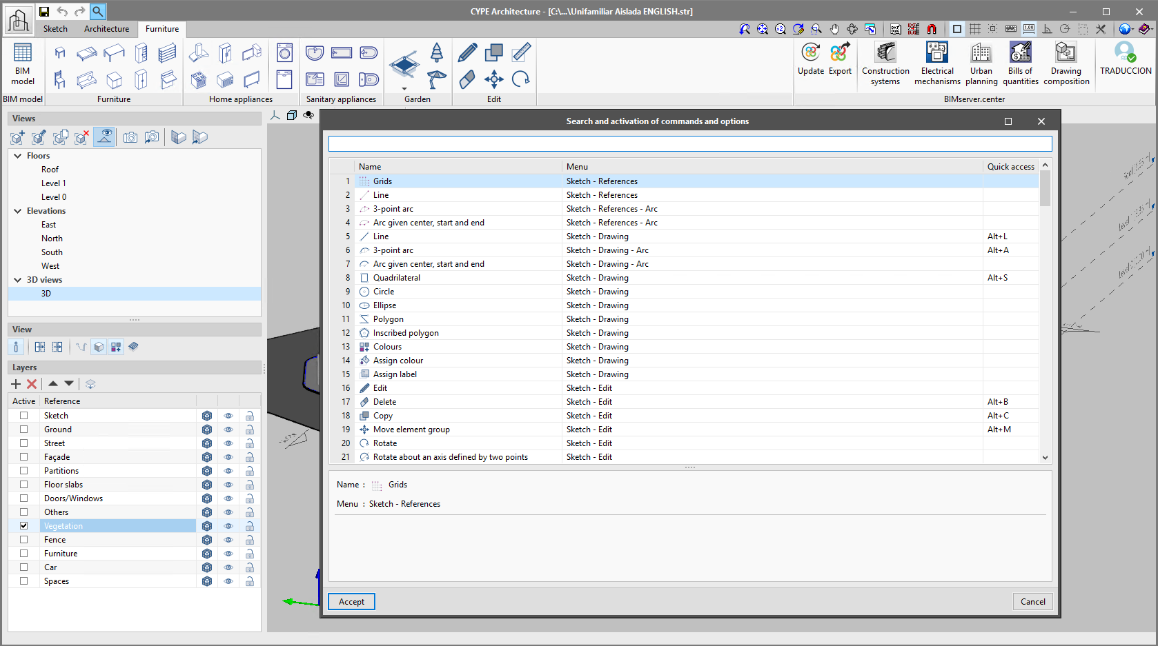
Search and activation of commands and options
Starting with version 2021f, the Open BIM applications available in the BIMserver.center platform "Store" include a new tool to search and activate the commands included in these programs. Access to this utility can be found next to the "Save", "Undo" and "Redo" buttons in the upper-left margin of the application interface.
In the "Search and activation of commands and options" window, for each command its name, location, shortcut key combination and description are shown. The reference entered by the user in the text field will be searched in all command names and locations for the purpose of filtering the list.
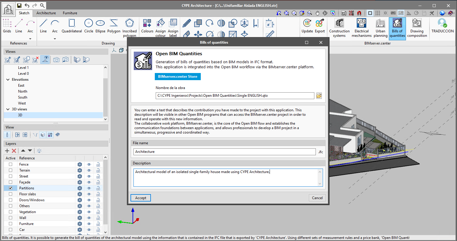
Improved connection between Open BIM applications
The connection of Open BIM applications which include direct links to other applications via the BIMserver.center platform has been improved. In previous versions, it was already possible to export the model to the BIMserver.center project via these links and then start the target application automatically. From version 2021f onwards, the link to the BIMserver.center project of the initial application is also sent to the application to which it is linked, so that the user does not have to select the project to which the linked application is to be connected again. Additionally, it is now possible to specify a file path and a name for the work in the target application so that, if the work already exists in the directory, the BIM project update process is opened and launched. This information is saved with the aim of streamlining the process in future exports of the model.
It is currently possible to find direct links in the following Open BIM applications:
- CYPE Architecture
- CYPECAD MEP
- CYPETEL Systems
- CYPETEL Schematics
- CYPELEC Electrical Mechanisms
- CYPELEC Distribution
- CYPELEC Core
- CYPELEC REBT
- CYPELEC NF
- CYPELEC RETIE
- CYPEDOC CTE HS 6
- Open BIM Accessibility
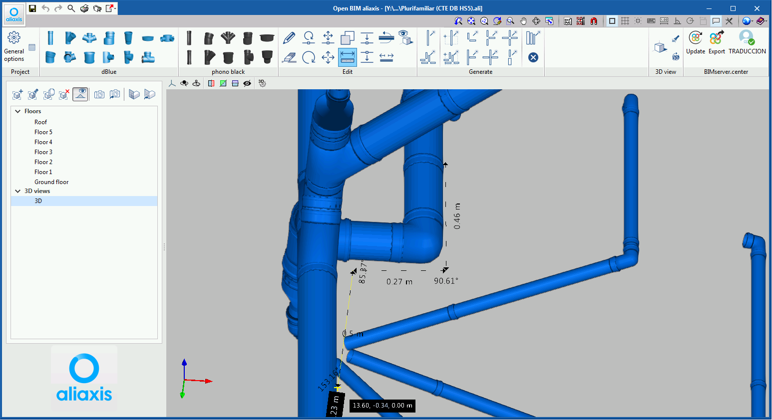
Angle values in the "Measure" tool
The "measure" tool, available in a wide range of applications, has been improved. It is now possible to display the relative angles between the length measurements made in the work area. The label containing the angle value, measured in degrees, will appear at the connection of each measurement.
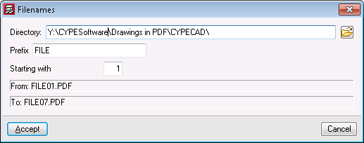
Generating plans in PDF format
As of version 2021.f, in any CYPE program that generates plans, if the "Microsoft Print to PDF" type is selected as the printing device, the program will request for a selection of file names to be generated.
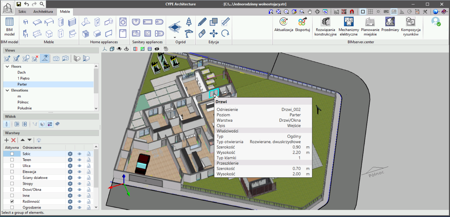
Applications in Russian and Polish
The following applications, which in previous versions were available for use in Catalan, Chinese, English, French, German, Italian, Portuguese and Spanish, are also available in Russian and Polish from version 2021.f onwards:
- CYPE Architecture
- Open BIM Model Checker
- Open BIM Layout
- Plugin Open BIM - Revit
- IFC Uploader
The BIMserver.center platform and its mobile applications (BIMserver.center Mobile, BIMserver.center Augmented Reality and BIMserver.center Virtual Reality) are also available in Russian and Polish.
Open BIM ISOVER
New duct textures
New textures have been added for the CLIMCover ranges.
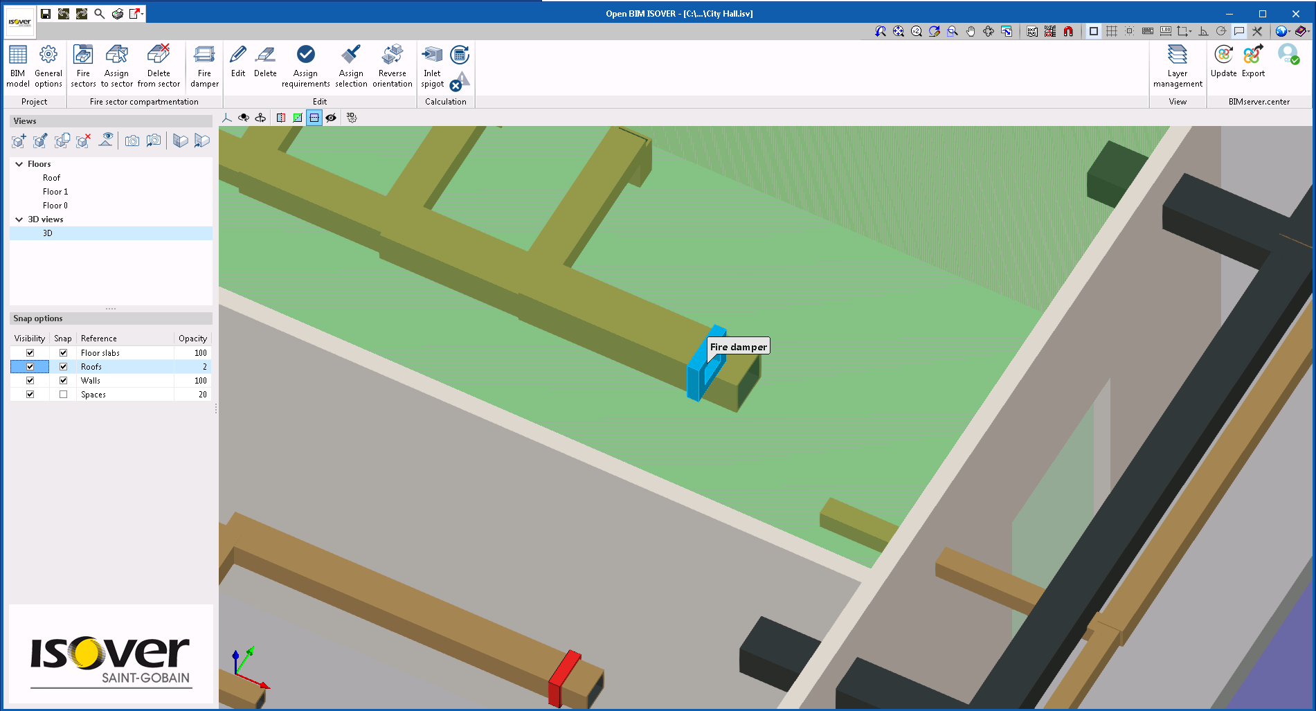
Fire damper introduction
Version 2021.f allows users to add fire dampers to the ducts read in the BIM project. For this purpose, when a damper is entered, all duct spans can be snapped.
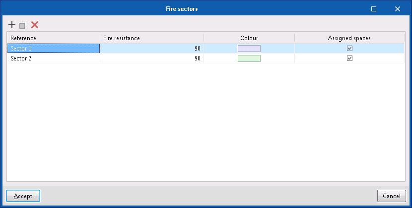
Defining fire sectors
As of version 2021.f, Open BIM ISOVER allows users to define fire sectors. Fire sectors can be defined in the program itself or imported from a BIM model included in a project on the BIMserver.center platform. Currently, CYPEFIRE Design or CYPEFIRE CTE programs can generate BIM models with fire sectors in a BIMserver.center project.
If the fire sectors are included in OPEN BIM ISOVER, users will have to define them in the program’s fire sector library and then assign them to the spaces imported from the BIM project.
In either of the two ways (fire sectors defined in the program or imported from a BIM project), the fire resistance requirements will be defined in OPEN BIM ISOVER and when users select the "Checks" option (Calculation group of the toolbar), the program will carry out the study of the duct networks in such a way that, if they do not have a fire damper, the most unfavourable fire resistance will be assigned to them.
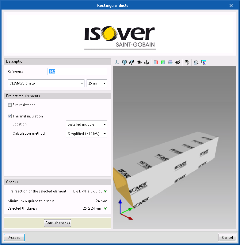
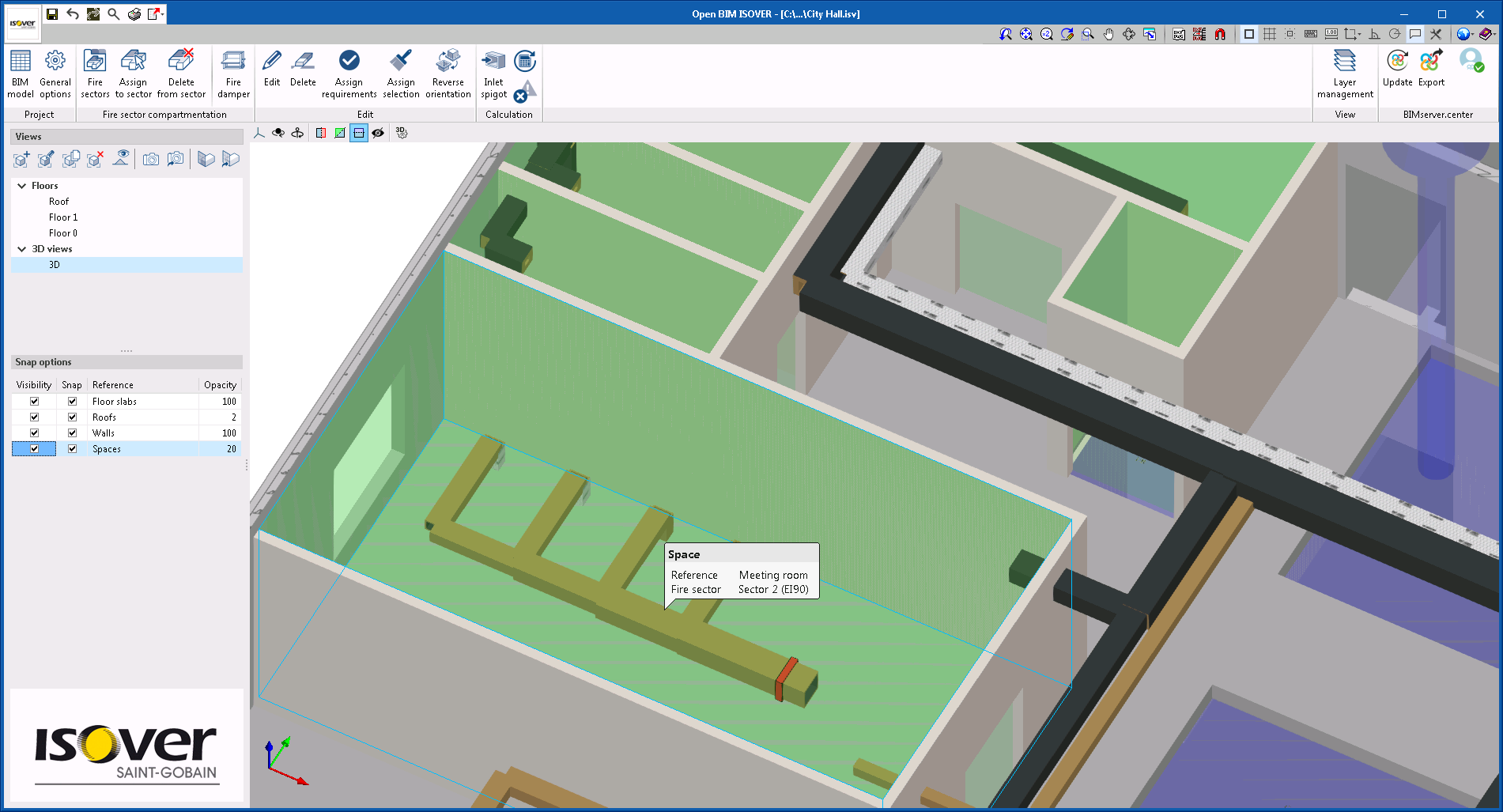
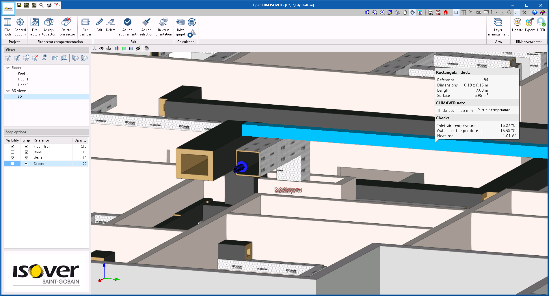
Checking duct network insulation using the alternative method
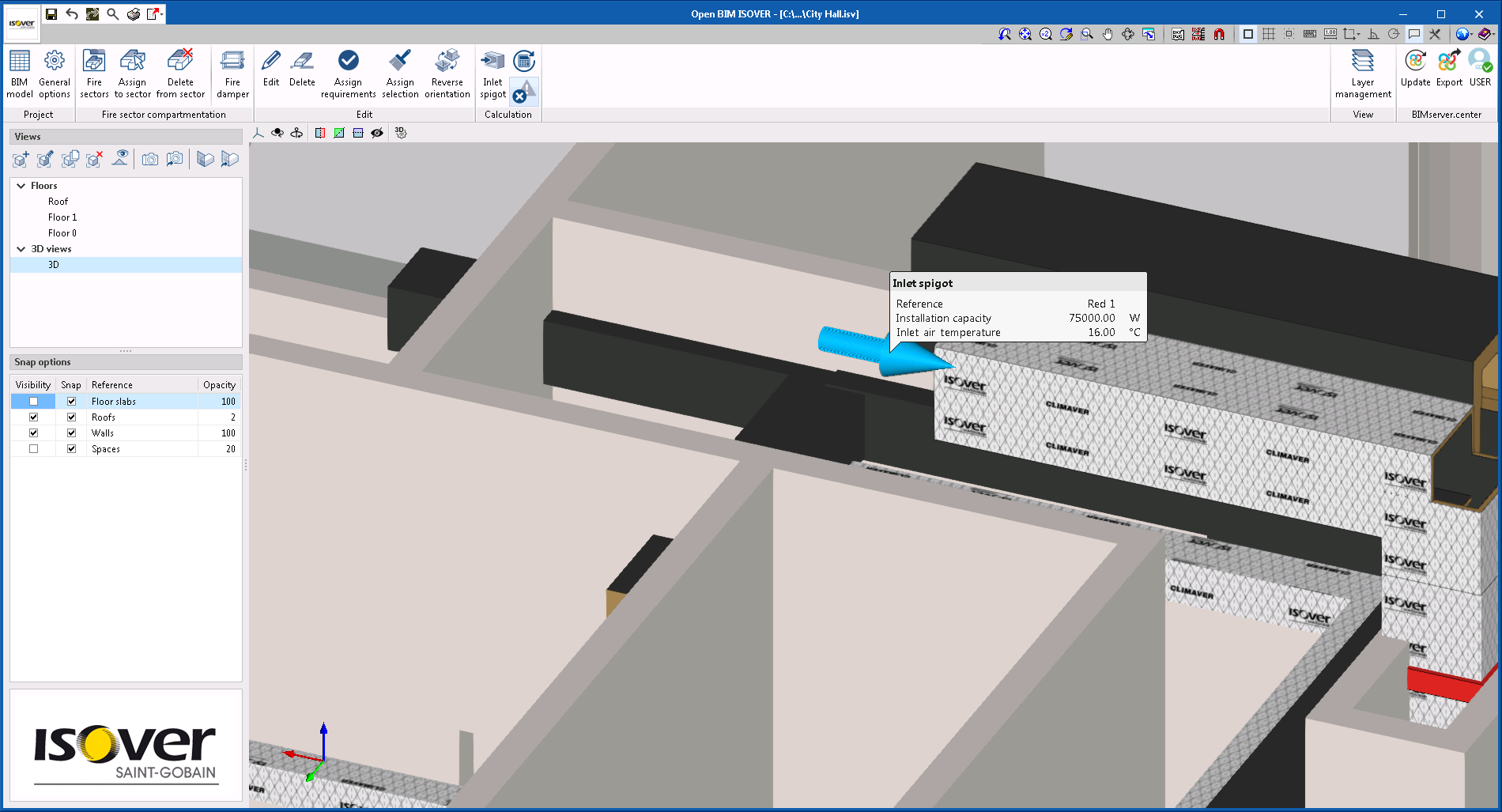
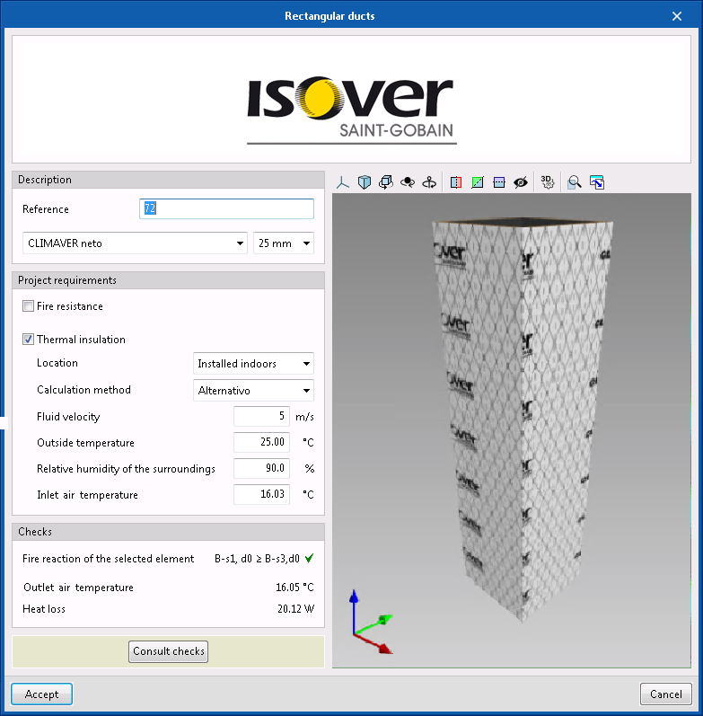
In version 2021.f, in addition to checking insulation thickness using the simplified method (for installations of less than 70 kW), it can also be checked by an alternative method.
To do this, users must include the inlet for the duct network in the program, where the following parameters can be defined:
- Installation power
- Inlet fluid temperature
Additionally, users must define the room temperature and relative humidity parameters for each space where a duct span is found.
With this data, once users select the "Checks" button (Calculation section in the toolbar), the program will calculate and display the heat loss of each of the sections onscreen, reading the outlet temperature of one section and the inlet temperature of the following section.
Open BIM MOVAIR
Installation modelling tool
Open BIM MOVAIR incorporates a tool that greatly streamlines the introduction of duct networks.
Since its first version (2020.a), the installation design was done by entering the different parts that comprise the duct network one by one: straight spans of ducts, reducers, elbows, branches…
From version 2020.f onwards, if the BIM project to which the Open BIM MOVAIR job is connected contains the design model of the ductwork installation (this model can be generated by CYPEHVAC Ductwork), the design of the installation can be quickly performed. From the ductwork installation design BIM model, Open BIM MOVAIR generates auxiliary paths with the necessary information to design the parts. With these paths, the application is able to automatically generate duct networks without having to enter the different parts of the installation one by one.
Open BIM PANASONIC
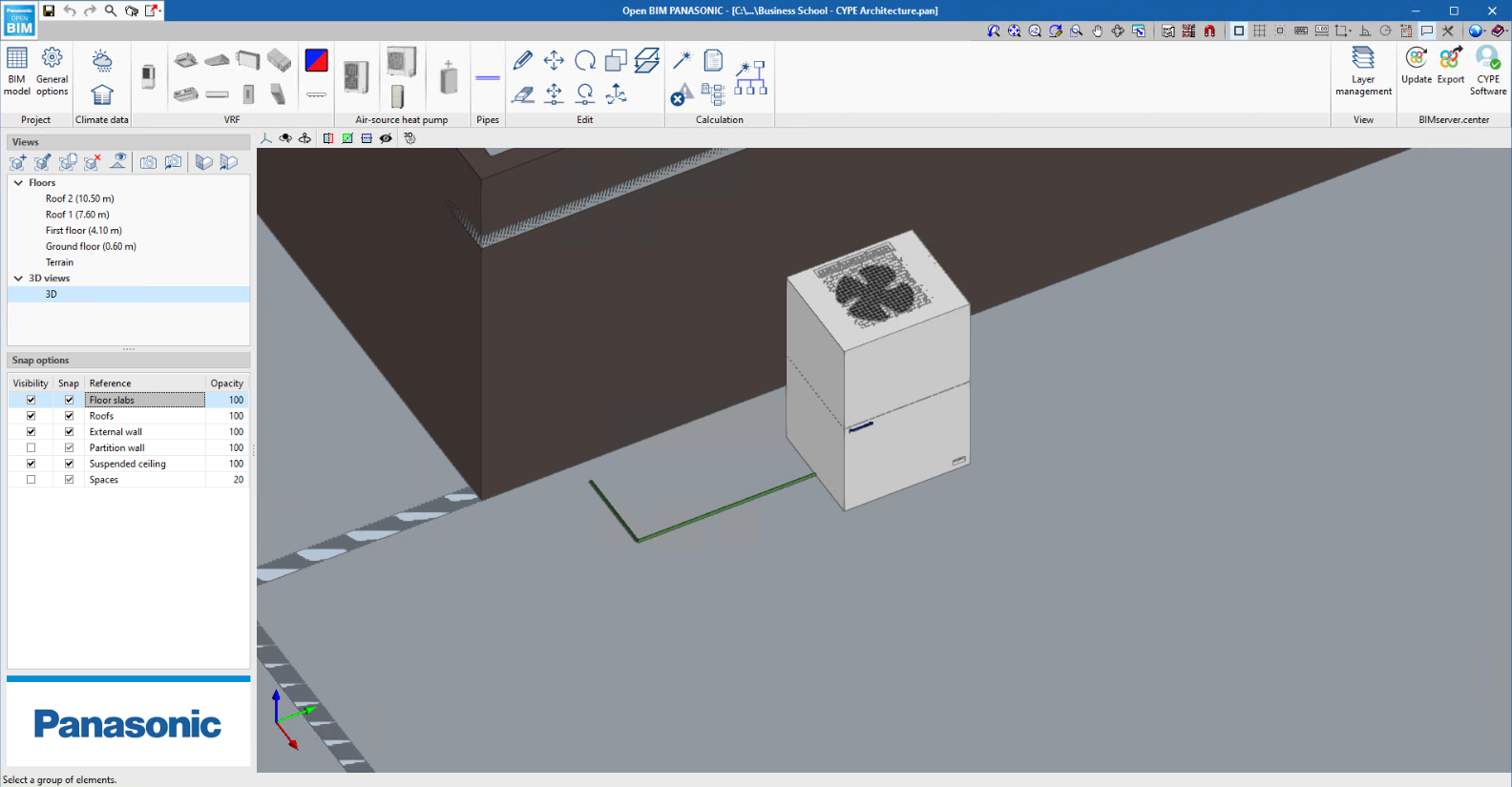
Automatic pipe design
Version 2021.f of Open BIM PANASONIC includes a tool that allows the user to create the path of the piping automatically.
With this tool, the user has to select one outdoor unit and one or more indoor units. After selecting, if the right mouse button is clicked, the program connects all units. If there were already pipes connecting the selected units before using the tool, these pipes will be removed.
In addition, if the selected outdoor unit is of the "heat recovery" type, the program will create a flow selection unit for each selected indoor unit. In this case, if the user changes the outdoor unit to a "heat pump" type unit and generates the design again, all flow selection boxes will be removed.
Pipe inlet at its real position
Now, the program depicts the pipe connection at the actual position of the equipment where the inlet is found. However, the equipment editing options (move, copy, etc.) are still performed from its central point.
Implementing regulations and improving their enforcement
Concrete structures
ACI 318-2019 (USA)
Building Code Requirements for Structural Concrete.
Implemented in CYPECAD, CYPE 3D and StruBIM CYPE 3D.
Rolled and welded steel structures
BS 5950-1:2000 (United Kingdom)
Structural use of steelwork in building - Part 1: Code of practice for design (Rolled and welded sections).
Implemented in CYPECAD, CYPE 3D and StruBIM CYPE 3D.
Cold-formed steel structures
AISI S100 - 2016 (USA)
North American Specification for the Design of Cold-Formed Steel Structural Members (USA).
Implemented in CYPECAD, CYPE 3D and StruBIM CYPE 3D.
AISI S100-2016 (Mexico)
North American Specification for the Design of Cold-Formed Steel Structural Members (Mexico).
Implemented in CYPECAD, CYPE 3D and StruBIM CYPE 3D.
CAN/CSA S136-2016 (Canada)
North American Specification for the Design of Cold-Formed Steel Structural Members (Canada).
Implemented in CYPECAD, CYPE 3D and StruBIM CYPE 3D.
Open BIM add-in for Revit and cost estimates and plans from BIM models
Compatibility of CYPE plug-in for Revit with "Revit 2022"
As of the 2021.f version, the CYPE plug-ins for Revit, "Open BIM add-in for Revit" and "Bill of quantities for BIM models", are compatible with the 2022 version of Revit.
CYPE Architecture
Types of architectural elements
In the "BIM Model" group of the upper menu of the "Architecture" tab, the new "Architectural element types" function can be found. With this it's possible to create construction element types that can be later loaded during modelling, thus saving time introducing the job elements.
Project types can be created for each of the following elements:
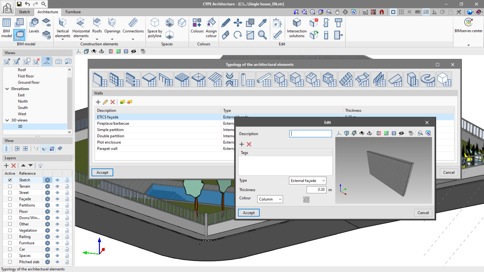
- Walls
- Curtain walls
- Louvres
- Railings
- Floor slabs
- Columns
- Beams
- Suspended ceilings
- Slope formation
- Roof tiles
- Ridges
- Valleys
- Windows
- Doors
- Skylights
- Glazed surfaces
- Stairs
- Ramps
- Landings
- Curved ramps
- Elevators
- Spaces
The project types can be saved locally to be loaded later into another CYPE Architecture project.
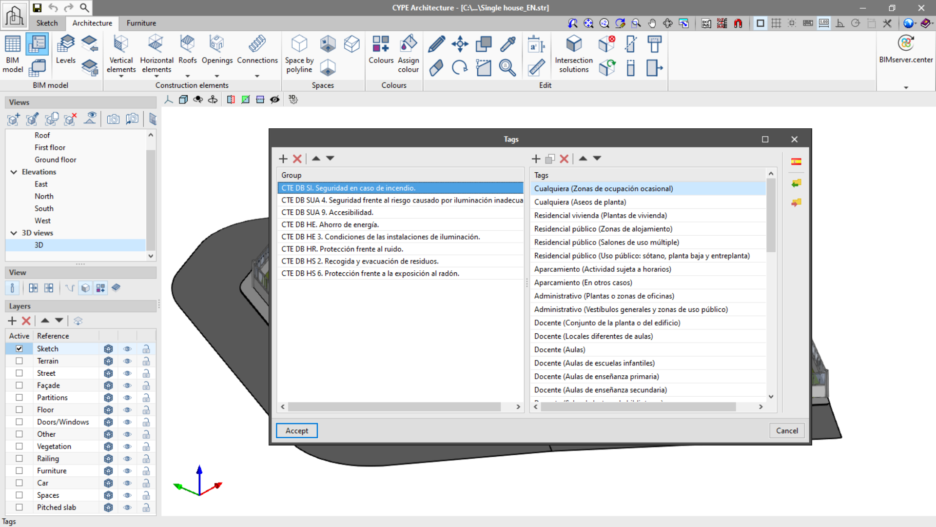
Improved label and label library functionality for Spain
The "Tag" function in the "BIM Model" panel allows the organization of tags in groups. In this way element tags can be ordered appropriately (for example, according to applicable standards).
Additionally, the program allows local exporting and importing of groups of tags so that they can be used in other CYPE Architecture projects.
The program also includes a tag library for Spain. This library allows the importing of groups of tags created according to the Spanish code.
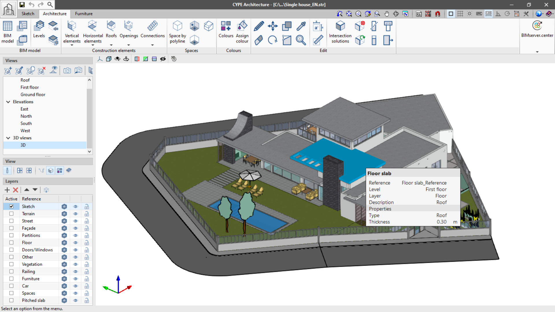
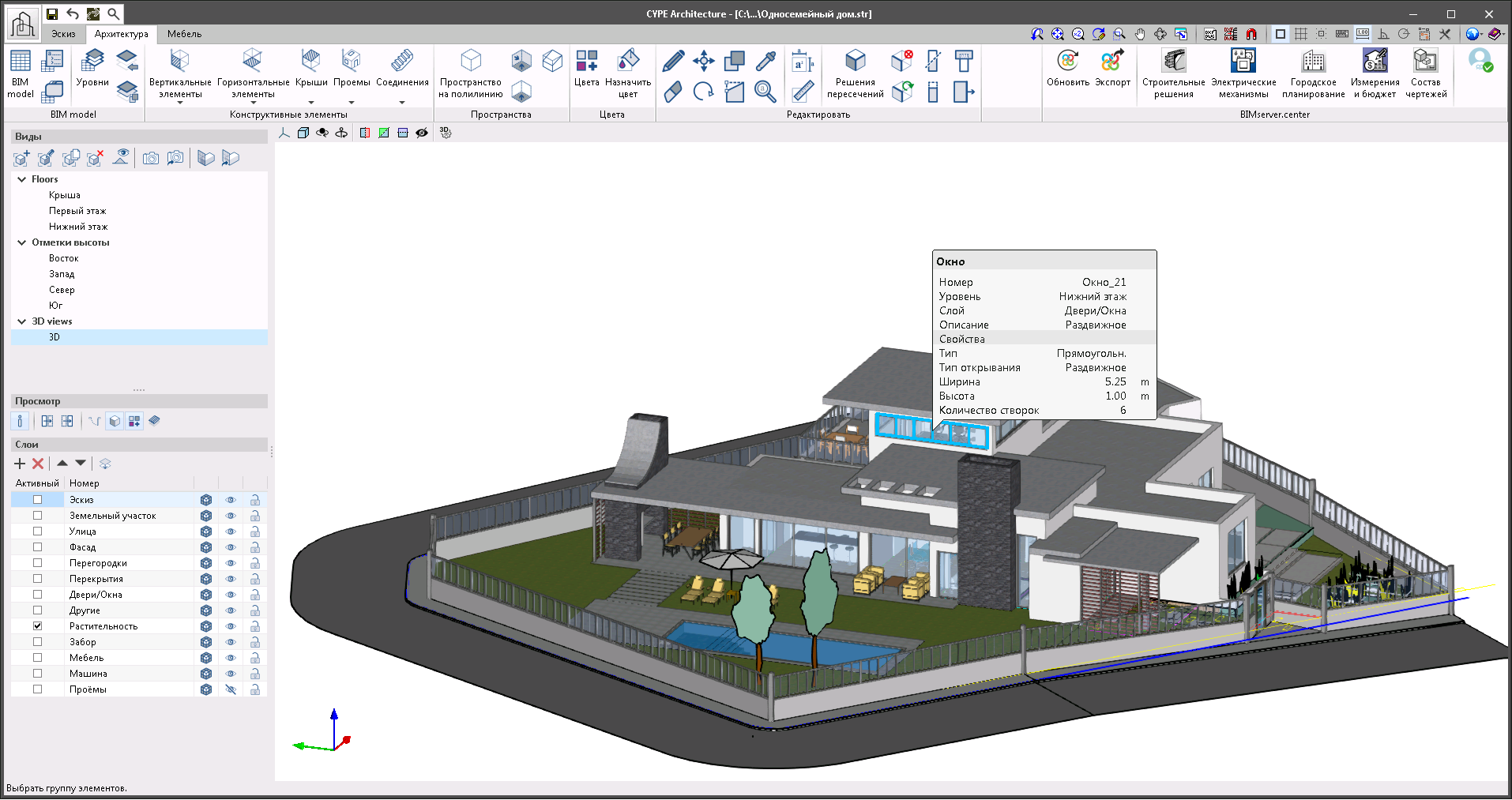
Show/Hide information
The new "Show/hide information" function is found in the "View" section of the left-side panel of the program. If enabled, it allows the display of any element’s information when the cursor is placed above it.
In the panel, information related to reference can be seen, such as the level, type, layer and the properties of each element.
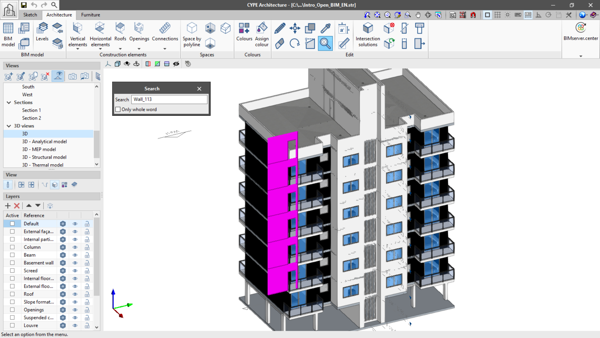
Search by reference
A new function, "Search by reference", has been implemented in the "Edit" group of the tool bar in the "Architecture" tab. This function allows searching elements by reference, thus easily identifying them. It is possible to locate only the references exactly as written (Only whole word) or all of the references that contain the text that is written.
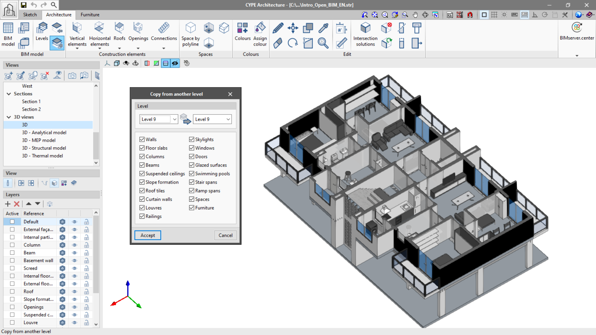
Copy between levels
This new feature can be found in the "BIM Model" group of the toolbar and allows copying the elements in the "Architecture" and "Furniture" tabs from one level to another in a simple way.
It is possible to choose the elements that we wish to copy between levels, which will be copied and assigned to the corresponding level.
Automatic solution of roof intersections
From version 2021.f onwards, the "Intersection solutions" function in the "Edit" group will solve intersections between floor slabs and roofs automatically.
Cut by face
When completing automatic intersection solutions, it is possible that an element has not been resolved correctly, leaving a small plane on one of its faces. To facilitate the correction in this case, the "Cut by face" (Edit group of the toolbar) tool has been introduced, which allows the removal of the excess plane and the adjustment of the element to the selected face.
Layer transparency
The table in the "Layers" panel, located on the left side of the screen, contains a new column which allows the layers to be made transparent. Clicking on the transparency icon, the display of the layer can be alternated between solid or transparent.
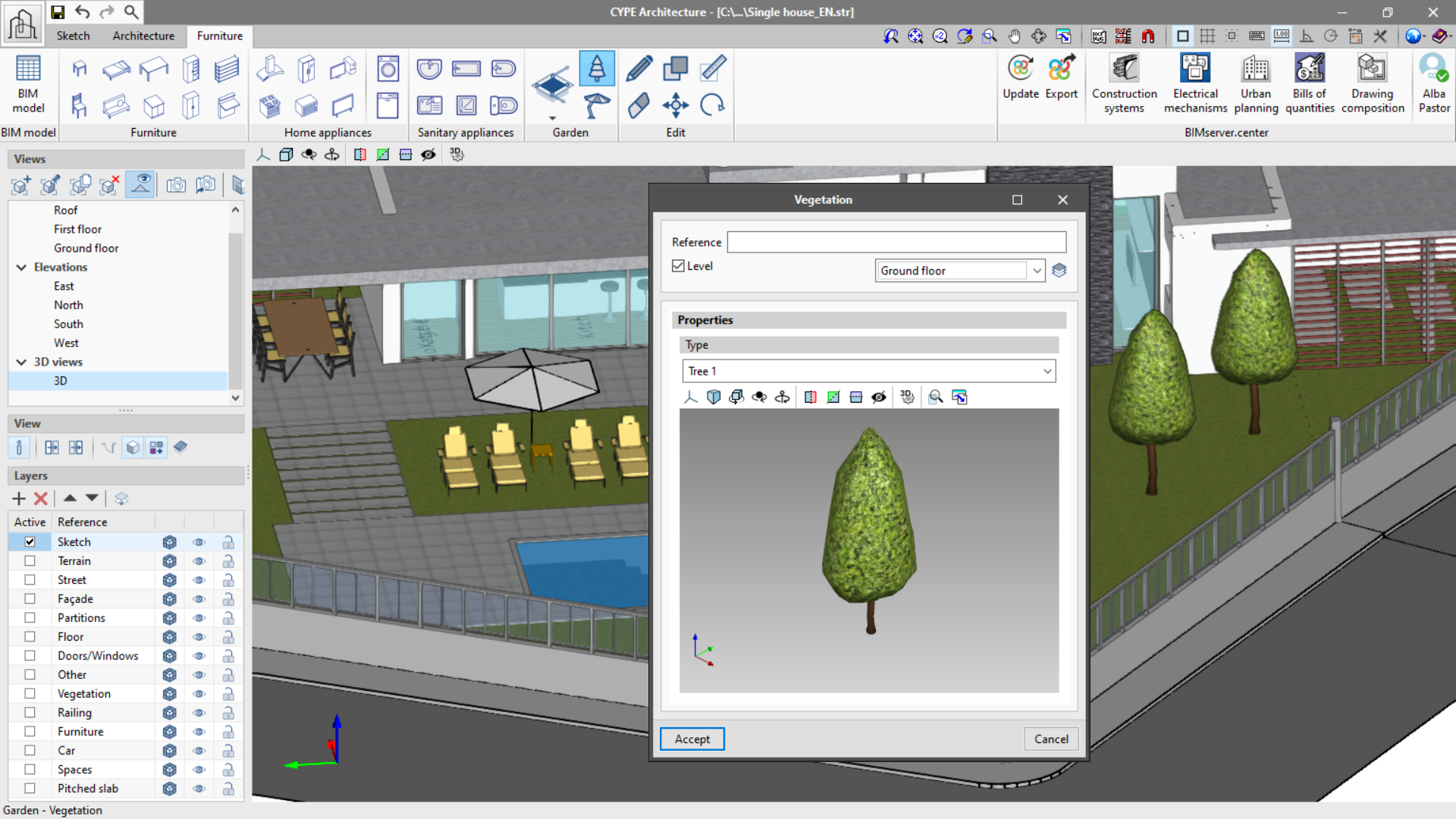
New garden furniture
The "Furniture" tab includes a new "Garden" group. With this group, "Pools" can be designed, and vegetation and exterior shade elements can also be added.
Improved dwg/dxf and 3D snap interaction for doors and windows
This improvement allows dwg/dxf and 3D model snap interaction, which allows the users that use dwg/dxf templates to have greater precision when it comes to inserting doors and windows on plan as well as in 3D, thus avoiding errors of not generating an opening in the wall.
Open BIM Construction Systems
Modifications in the descriptive report
The justification documents for the descriptive report of the project’s building envelope and partitioning system has been modified. Now, the construction system references do not appear in the index. This decision is due to the fact that the "description" field of the system definition panel is usually left blank, and the text used as a "reference" is sufficient for the descriptive report. This resulted in a list with an index that was equivalent to the content.


3D file size reduction
The exporting of construction systems' 3D models in glTF format has been optimised for Open BIM program viewers, for the BIMserver.center platform viewer, and for BIMserver.center mobile applications. This has led to an improvement in viewer performance, as well as in uploading and downloading files to the BIMserver.center platform.
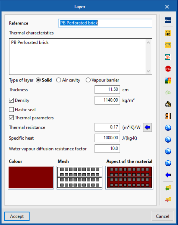
Optional density value in construction system layers
As of version 2021.f, entering the density value of a construction system layer is optional. If this value is not entered, it cannot be read in thermal and acoustic analysis applications.
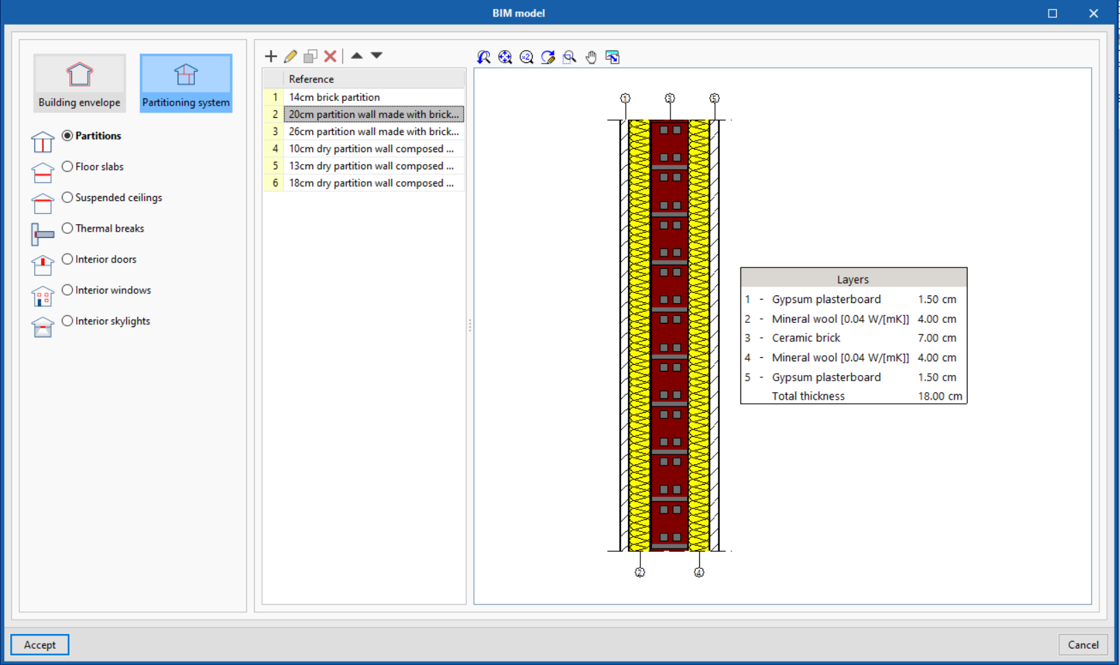
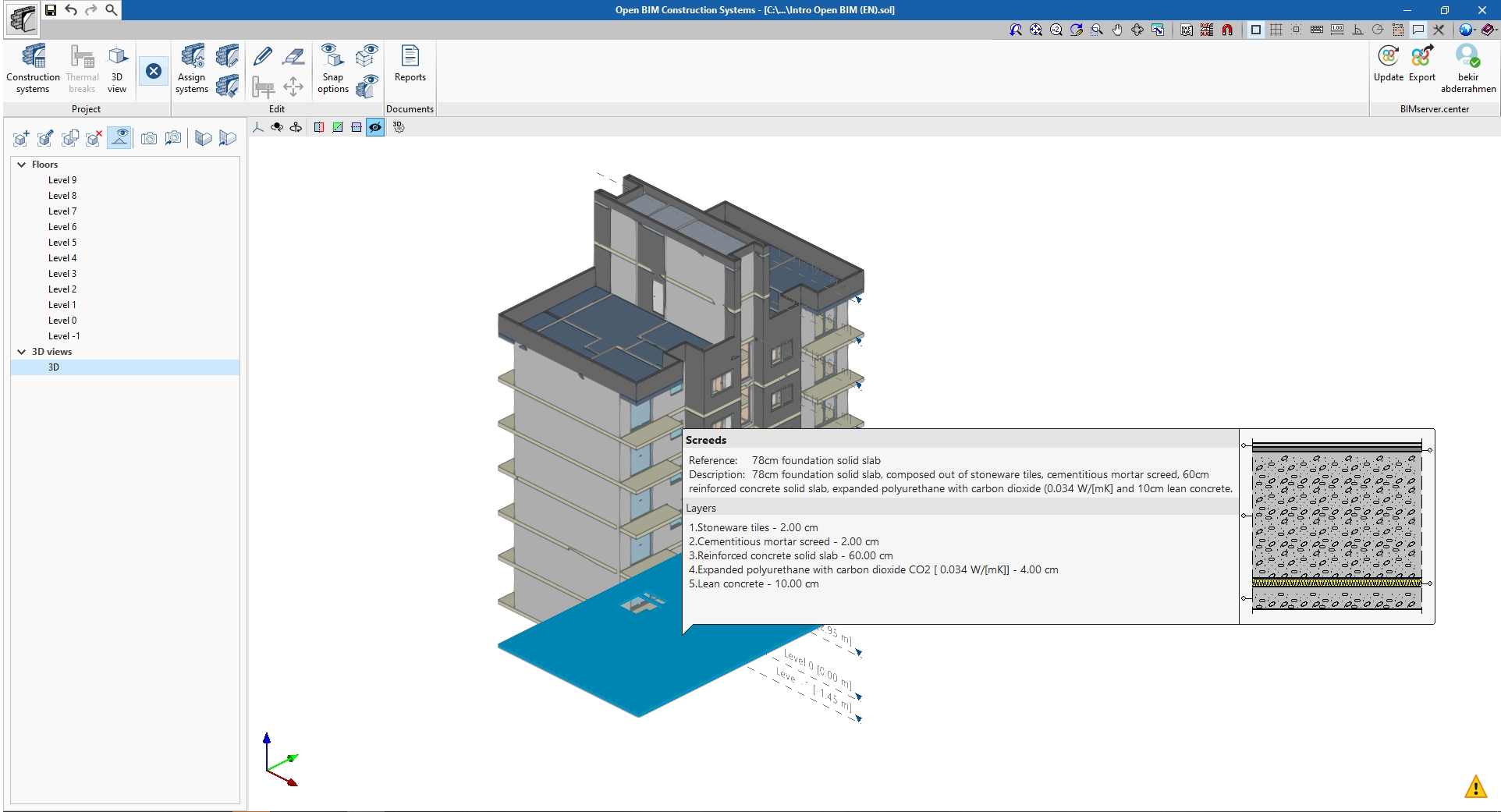
Total thickness of the construction system
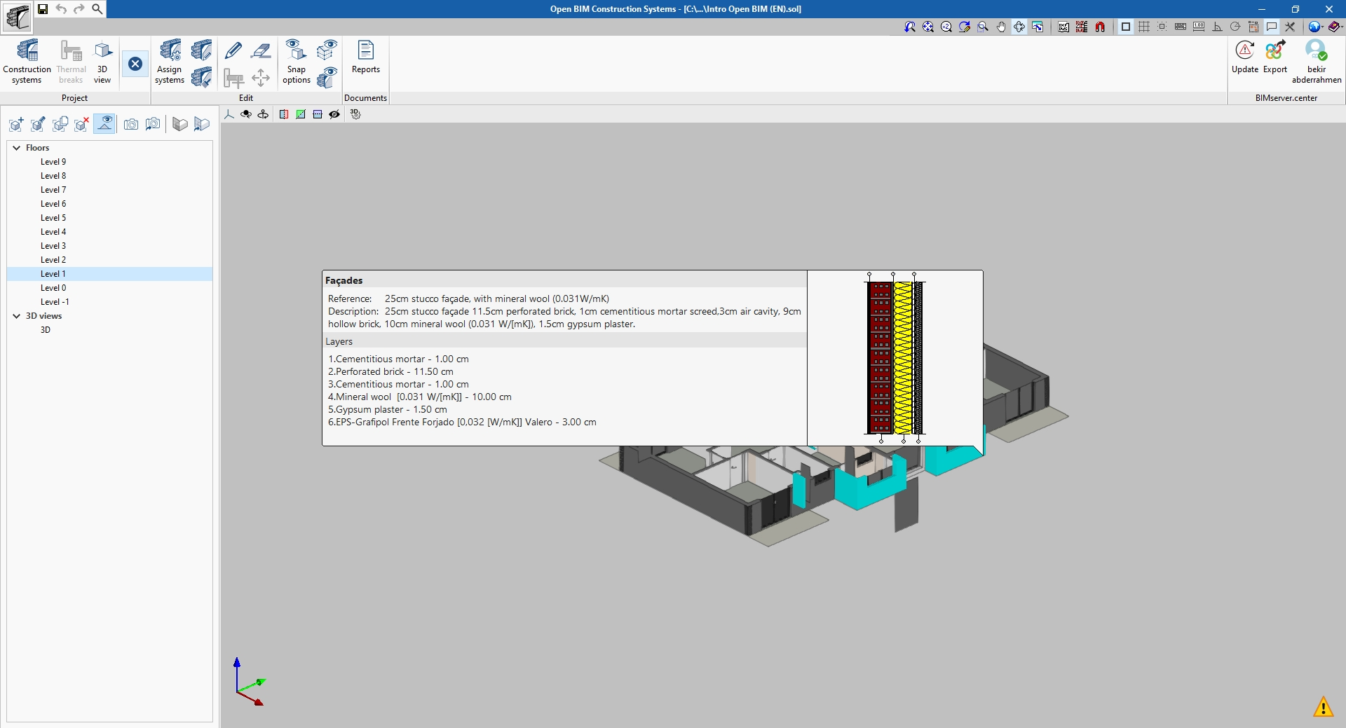
As of version 2021.f, Open BIM Construction Systems displays a total thickness analysis of the constructive systems made with several materials. The total thickness is obtained from the sum of each individual layer's thickness. This way, we can easily check whether the construction system's thickness corresponds with the thickness assigned to the element in the architectural BIM model.
"Edit" and "Delete" options for construction systems
It is now possible to use the "Edit" and "Delete" options available in the "Edit" group of the Open BIM Construction Systems toolbar for the construction systems assigned to architectural BIM model components located in the work area. The "Edit" button can be used to change the assignment of the construction system to a model element. Alternatively, the "Delete" button can be used to remove the assignment of a construction system to one or more of the model’s elements.
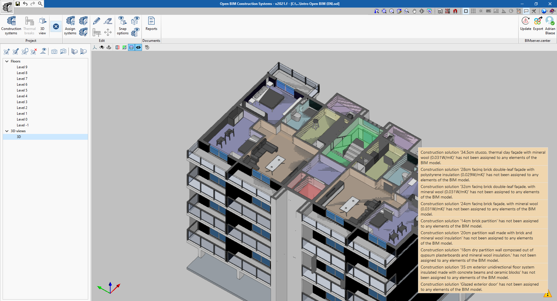
Construction systems pending assignment
As of version 2021.f, Open BIM Construction Systems displays a warning when constructive systems have been defined in the project but have not been assigned to elements in the architectural BIM model. Unassigned systems will appear in the documentation generated by the application; however, they will not be read in thermal and acoustic simulation programs.
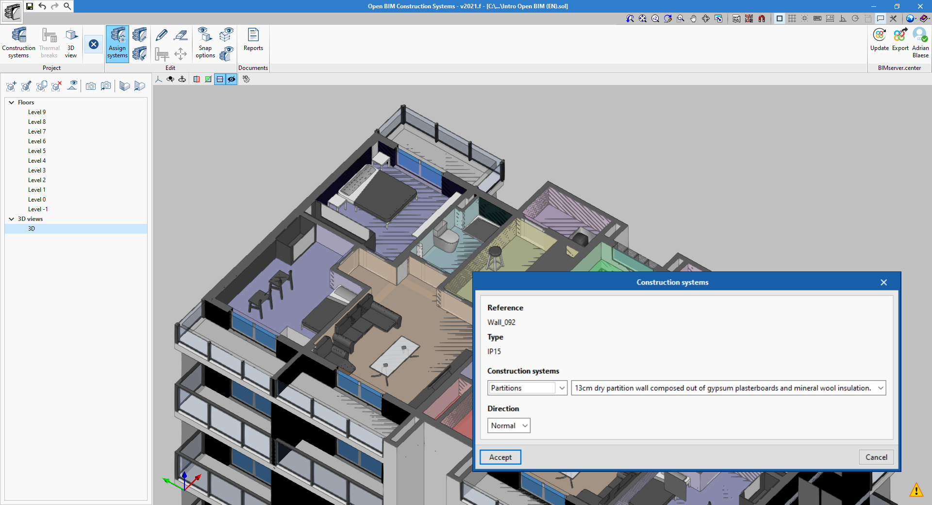
Assigning construction systems by type
From version 2021.f onwards, the "Assign" option in the "Edit" group of the application’s toolbar will allow constructive systems to be associated to elements in the architectural BIM model according to their typology. When this option is used, the system will be assigned to all components sharing the same reference type.
New example job
The example job "Intro Open BIM (EN)" has been added with the project’s constructive systems defined in English.
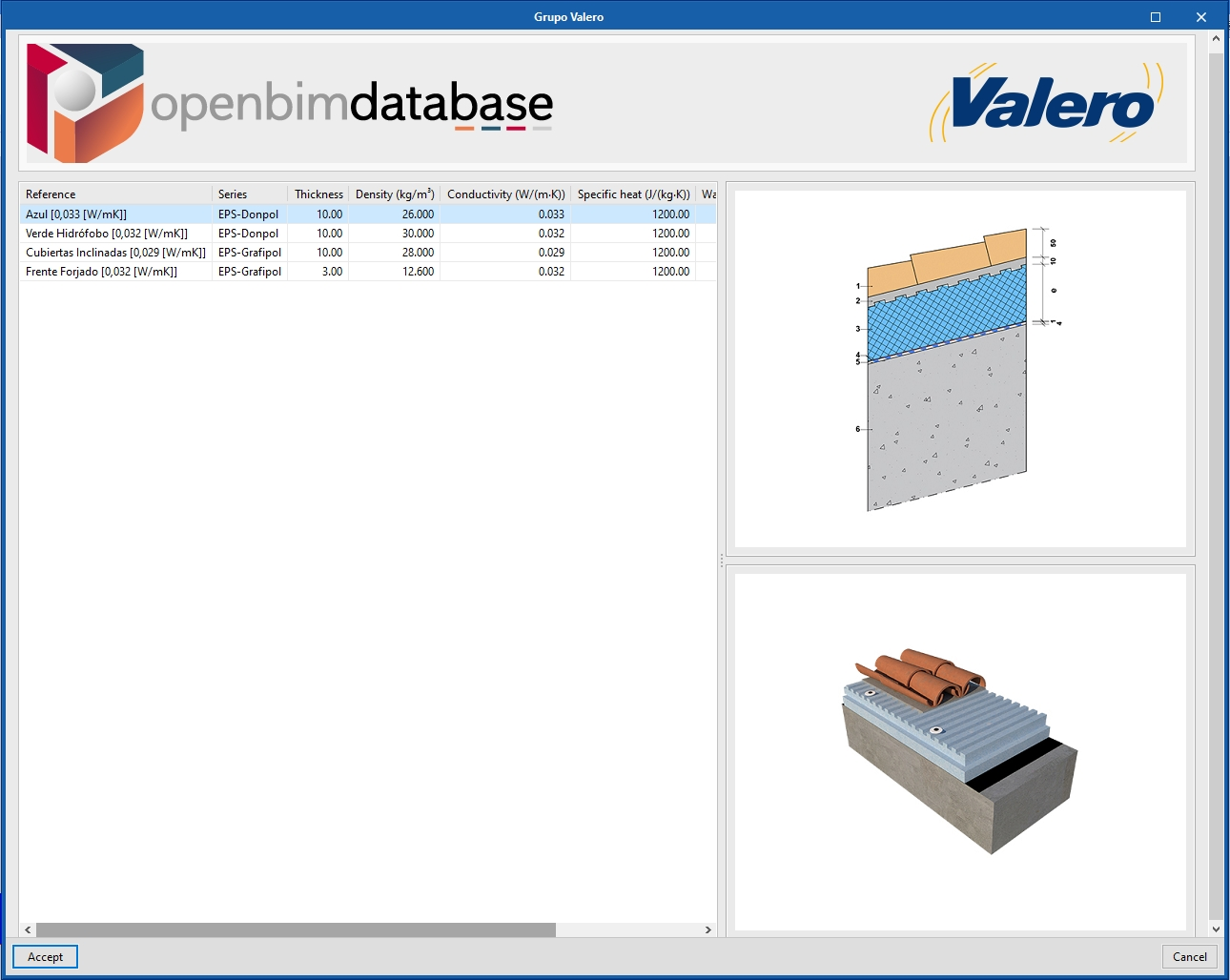
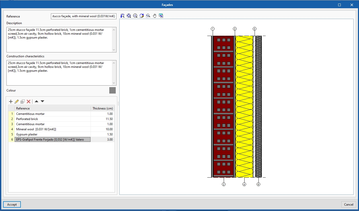
Importing insulation products by Grupo Valero
From version 2021.f, it is now possible to import insulation from the manufacturer Grupo Valero to be used as layers of a construction system. In the layer definition panel, the Grupo Valero icon now appears on the right-hand side of the window. By clicking it, users can access the manufacturer's database for an updated list of their available insulation products. Users can browse the products in order to select the appropriate one and, by accepting the panel, its properties will be imported into Open BIM Construction Systems.
When the construction system’s definition and assignment are exported to the BIMserver.centre platform project, the thermal and acoustic analysis tools will be able to read all the technical characteristics for the insulation. This will ensure the consistency of the data at all stages throughout the project.
The import of Grupo Valero's construction systems is also included, from this version onwards, in the CYPETHERM LOADS program.
Although the Grupo Valero icon on the layer definition panel is displayed in every language that the application is installed in, the manufacturer's insulations shown are for the Grupo Valero products supplied in Spain.
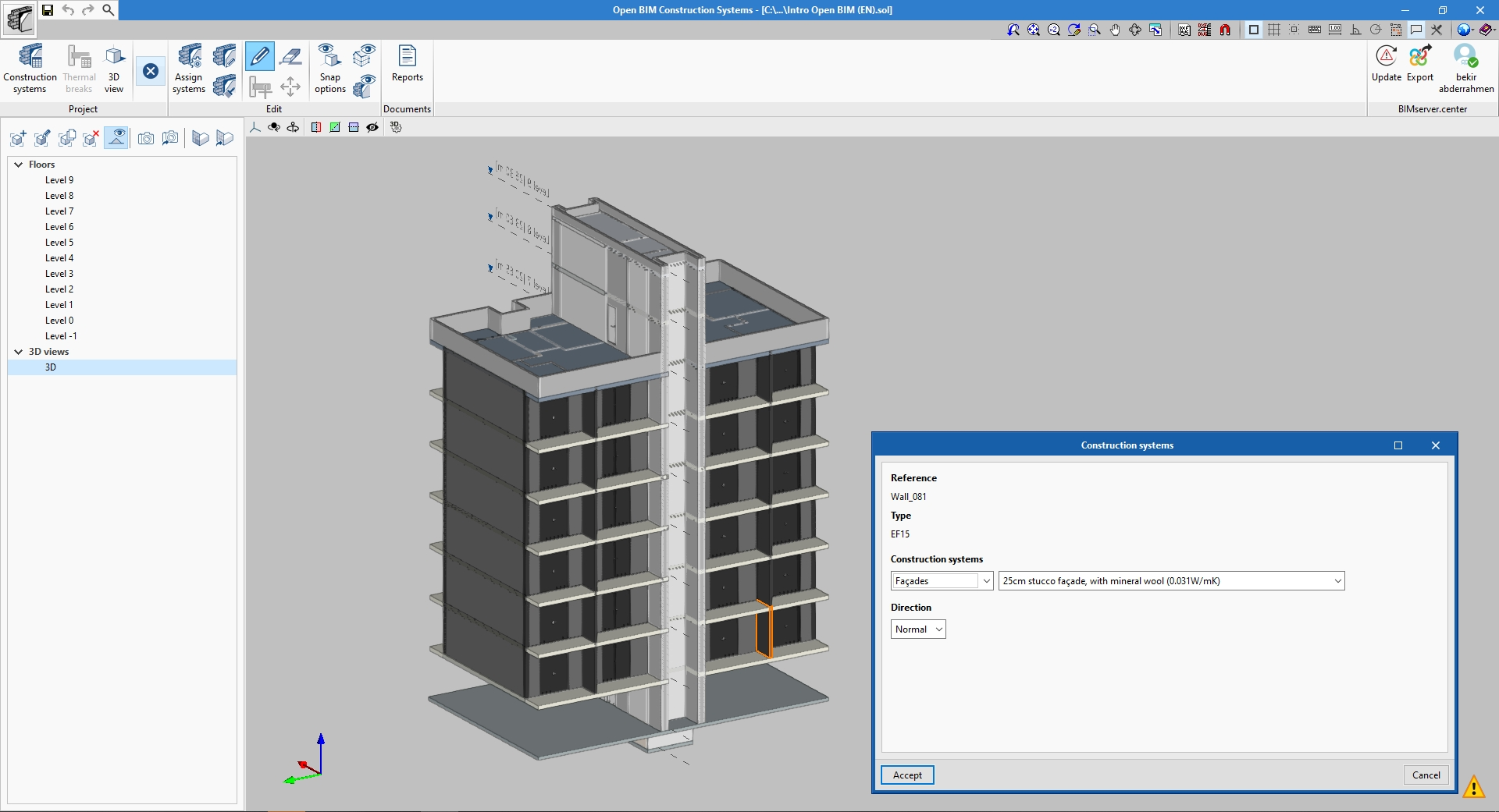
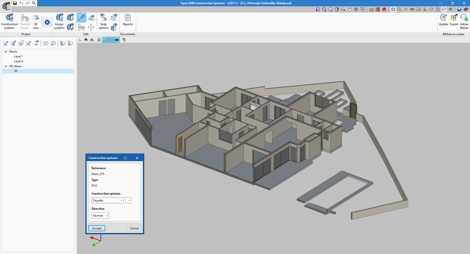
Invert introduction direction
The "Direction" field has been added to the panel for assigning construction systems to the components in the architectural BIM model. Thus, it is now possible to invert the introduction direction of material layers in non-symmetrical systems.
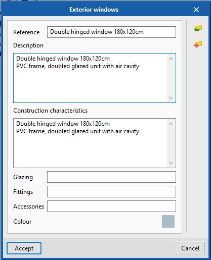
New fields for defining windows and skylights
Three new fields have been added to the definition panel for window and skylight systems:
- Glazing
- Fittings
- Accessories
If a reference for any of these parameters is indicated, it shall be shown in the construction report’s justification documents for the building envelope and partitioning system.
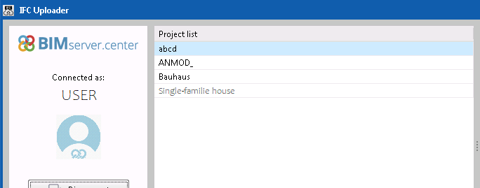
IFC Uploader
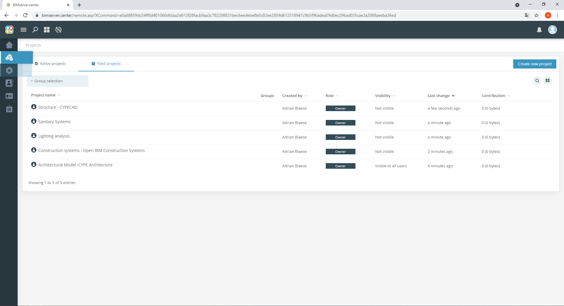
Sortable project list
Starting with version 2021.f, IFC Uploader allows alphabetical sorting of the list of projects on the BIMserver.center platform associated with the user that is logged in. This makes it easier for users with a large number of projects to locate a specific project.
Open BIM Layout
User manual
A user manual for the program is included. The manual can be accessed from the program itself ("Help" button in the upper right corner of the screen) or from the "Available resources" section of the program's profile on the BIMserver.centre platform (next to the download button).
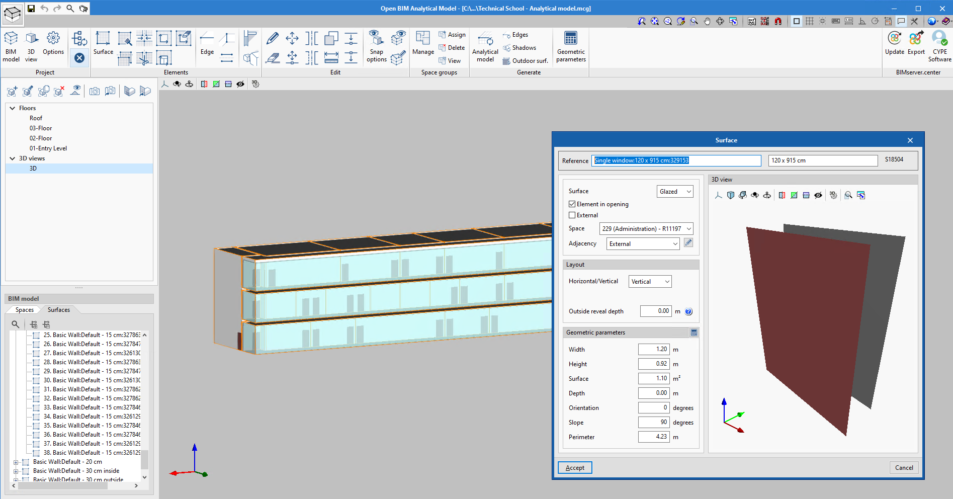
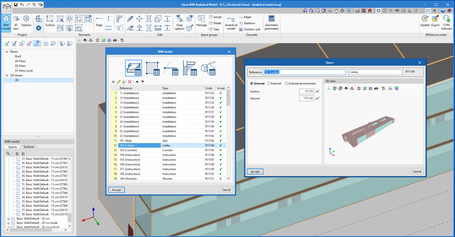
Open BIM Analytical Model
Outside reveal depths of doors and windows
The "Outside reveal depth" field has been added for defining surfaces in the analytical model for opening elements such as doors and windows. This amount can be used by thermal simulation applications.
The outside reveal depth of the door or window is entered from the external surface of the construction element.
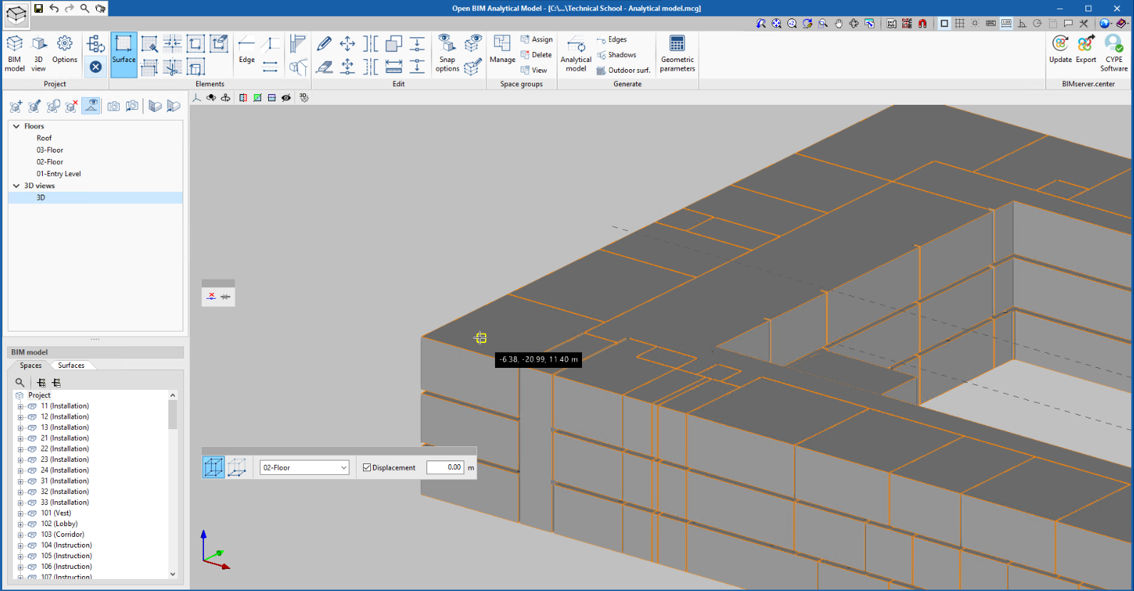
Improved object snaps in spaces
There has been an improvement for object snaps in volumes matching the spaces of the physical model. In previous versions, some points in spaces containing complex 3D geometries could not be snapped correctly when entering analytical model elements such as surfaces or edges.
Improved precision in the algorithm for automatically generating analytical models
There has been an improvement in the algorithm for automatically generating analytical models mainly in the following areas:
- The problem that prevented updating the properties of the analytical model's spaces (surface area, volume...) when they were modified in the physical model has been corrected.
- An improvement has been made to the process of detecting surfaces in the analytical model using the physical model's spaces and constructive elements.
- An improvement has been made for linking analytical model surfaces generated with the same properties.

Editing project north
As of version 2021.f, Open BIM Analytical Model allows users to edit the northern direction of the analysis model. To modify its value, an "Options" button has been added to the application's toolbar where users can specify the model’s orientation. If there is already a physical model in the linked BIMserver.centre project, Open BIM Analytical Model can read the value of this model’s orientation, if it has been defined. The angle describing the orientation corresponds to the offset between the Y-axis direction of the scene and the north, in an anti-clockwise direction.
The north direction is shown in the bottom left margin of the work area corresponding to the floor views that have been defined for the Open BIM Analytical Model project.
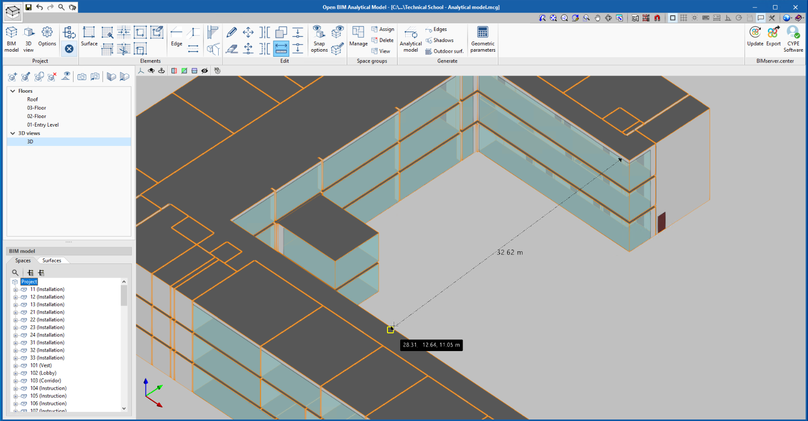
Object snaps in the "Measure" tool
As of version 2021.f, the "Measure" tool available in the "Edit" group of the application's toolbar allows users to apply the object snap of the model’s components. This way, a higher degree of precision can be obtained for measurements when they are carried out in relation to the position of the 3D elements in the Open BIM Analytical Model work area.
CYPECAD and CYPE 3D
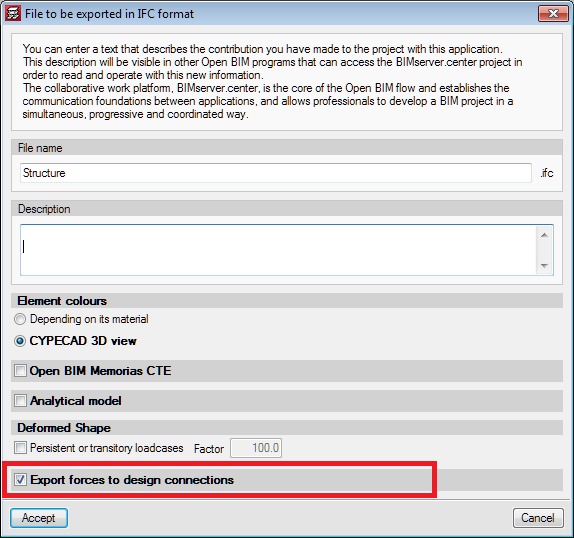
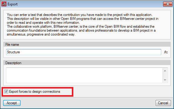
Exporting forces in bars for the analysis of connections in StruBIM Steel and CYPE Connect Steel
In version 2021.f of CYPECAD and CYPE 3D, the "Export forces to design connections" option has been added to each respective export dialogue from the design model to the BIM project on the BIMserver.center platform that they are connected to.
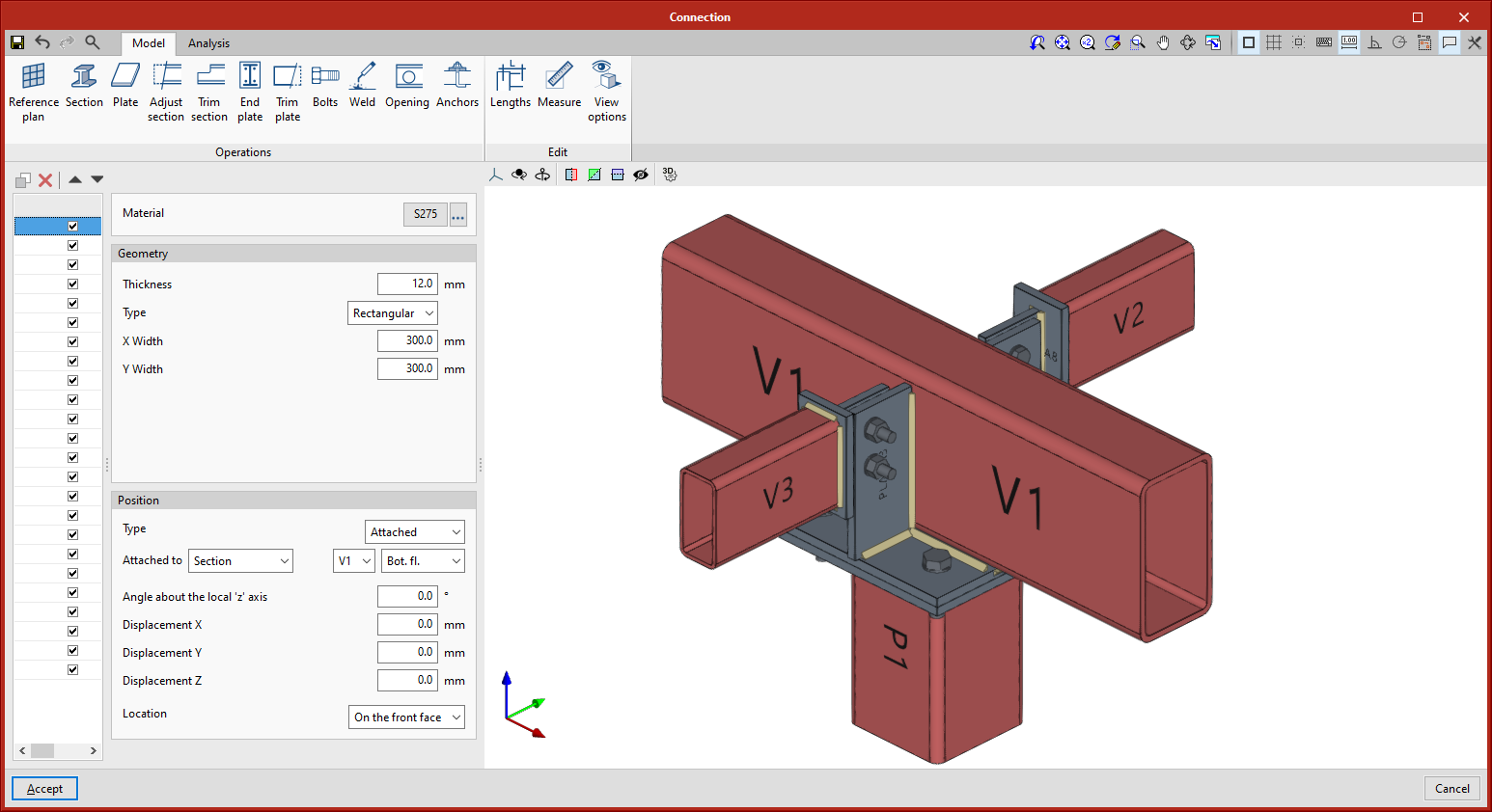
When this option is selected in CYPECAD or CYPE 3D, the forces designed at the ends of the steel elements (beams, columns, and also, in CYPECAD, bars in integrated 3D structures) are exported to the BIM project for the hypotheses of the combined actions included in the latest limit states.
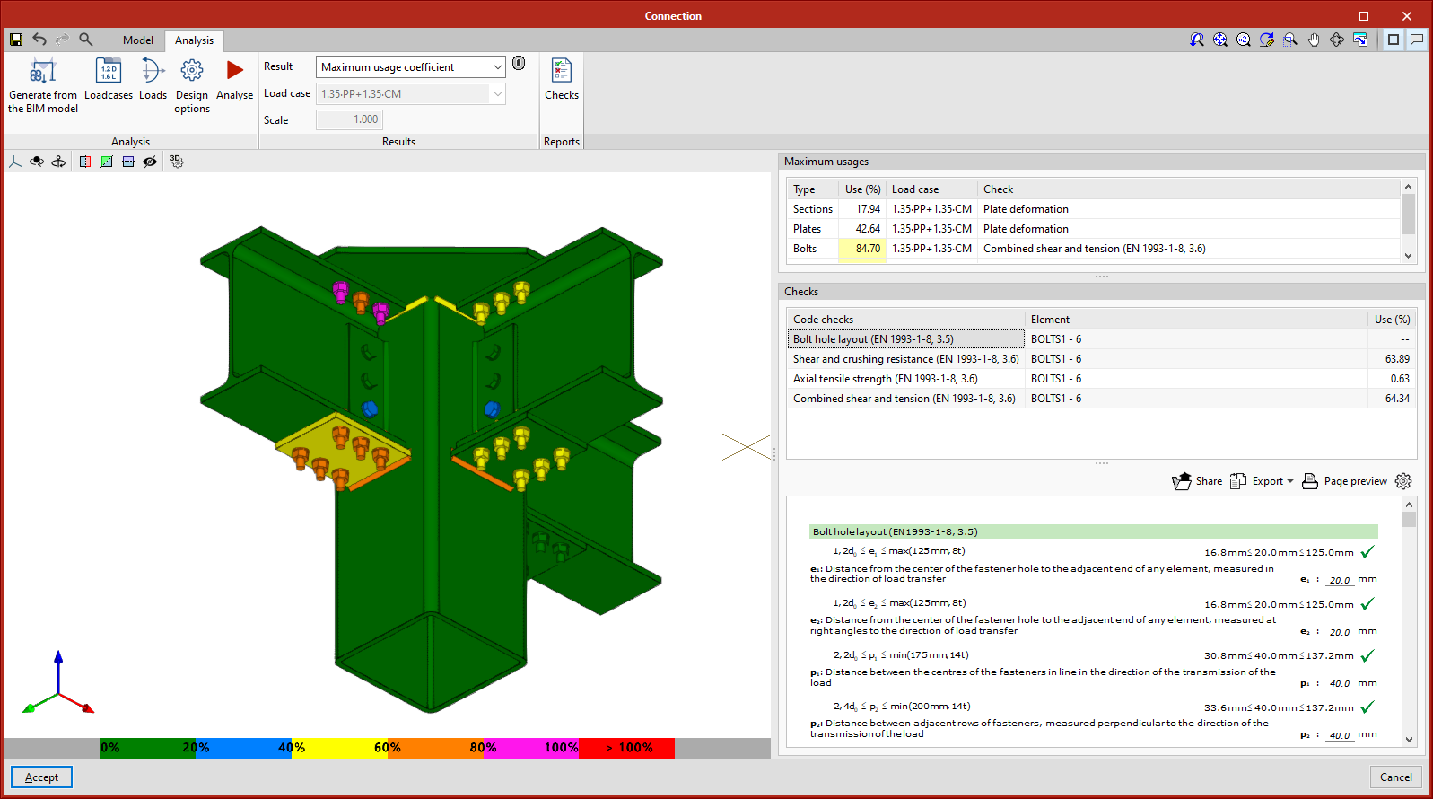
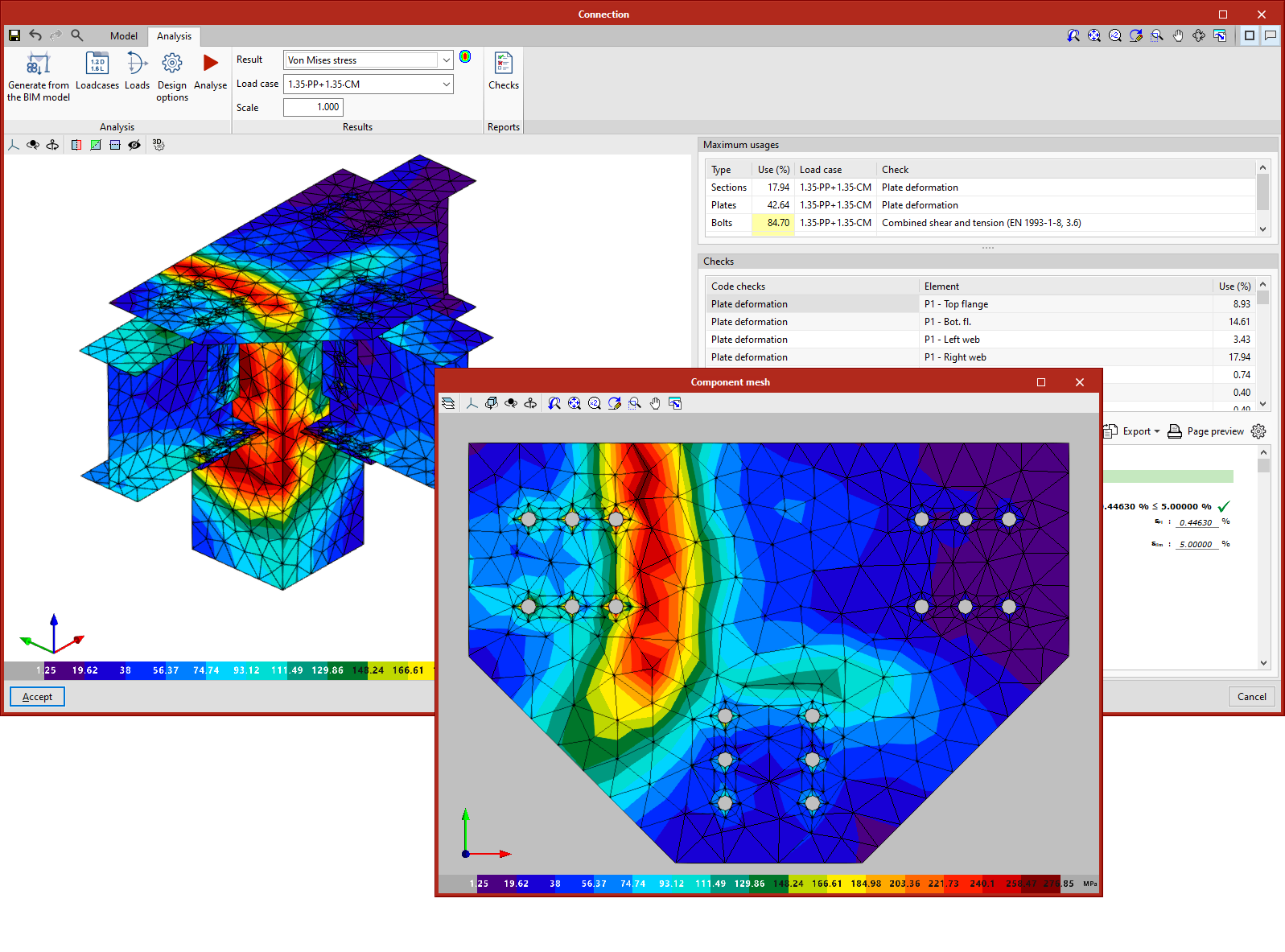
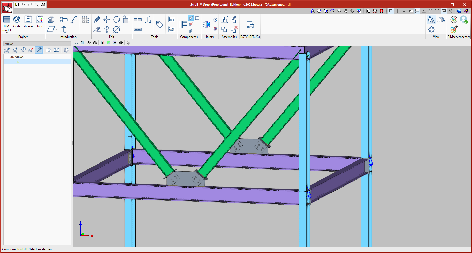
Thus, the forces are available for modelling and designing the connections of this project in the CYPE Connect Steel and StruBIM Steel programs (shown in the attached image of the editor for modelling and analysing connections which is included in both programs).
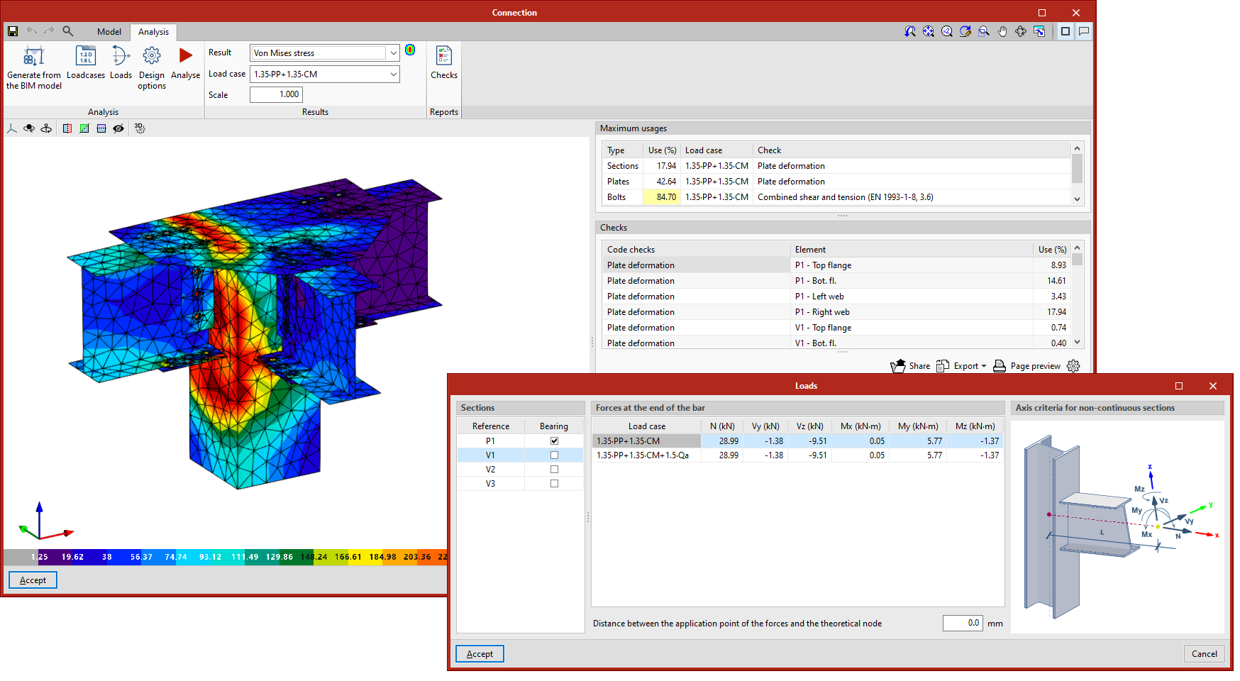
Soon, this editor will also be available for CYPECAD and CYPE 3D.
More information on CYPE Connect Steel.
Find out more about the new features in StruBIM Steel 2021.f.
CYPECAD
Customisable reports
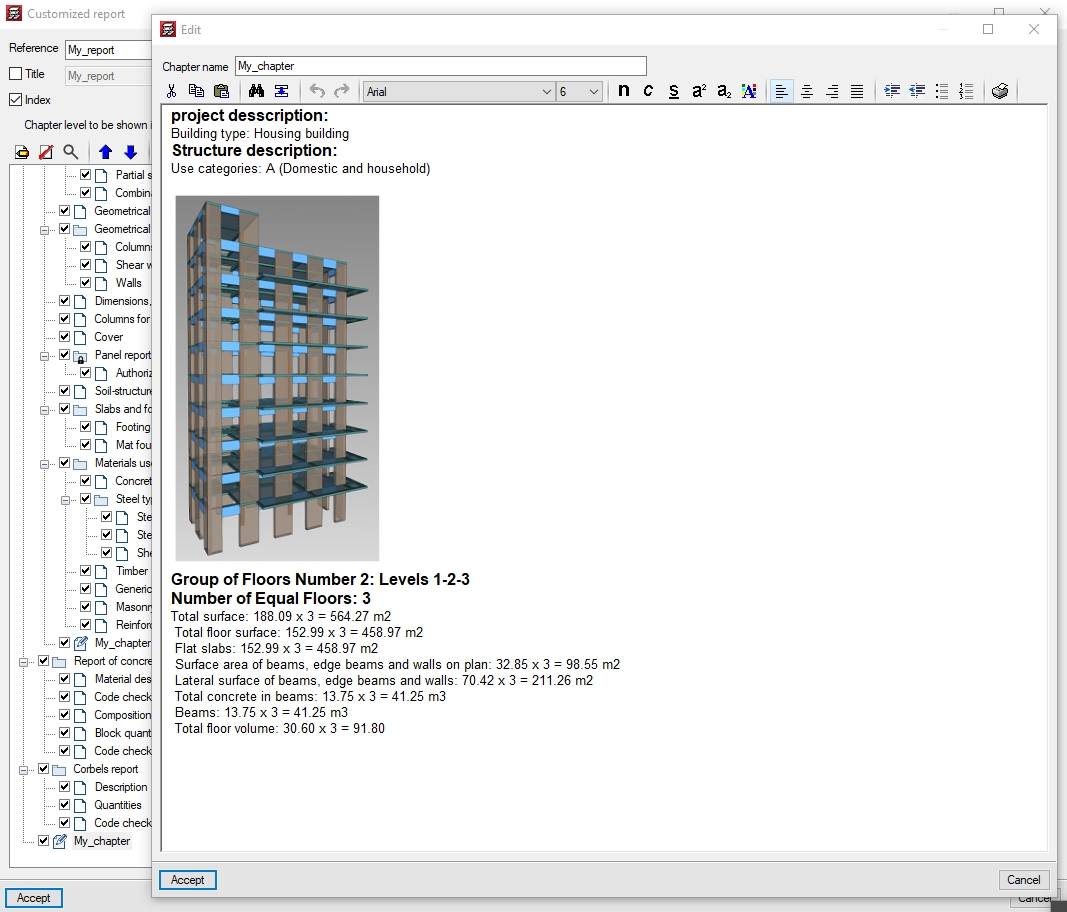
Add section with an editable document
It is possible to define a section with information created by the user. This information can be added directly or copied from an external document.
This document can include tables, images, and formulas, as well as plain text. The reports including these types of sections must be exported to PDF to view them correctly.
Default reports
The following default reports have been added for being included optionally as sections in customisable reports:
- Node displacements in slabs and waffle slabs
- Node forces in slabs and waffle slabs
- Rectangular slab report
- Global stability analysis report
Allowable tolerance for resistance checks
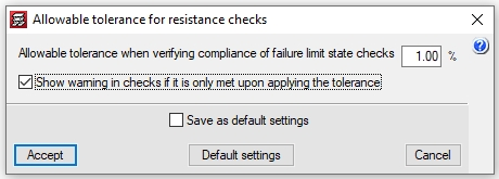
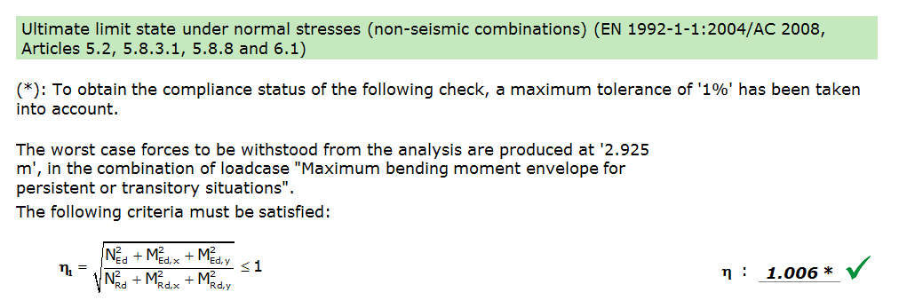
The "Allowable tolerance for resistance checks" option has been added to "General options". Using this option, users can configure the allowable tolerance when verifying the compliance of failure limit state checks.
Additionally, it is also possible to select whether or not a warning is displayed in the checks, in case compliance is verified as a result of the configured tolerance.
Shear wall options
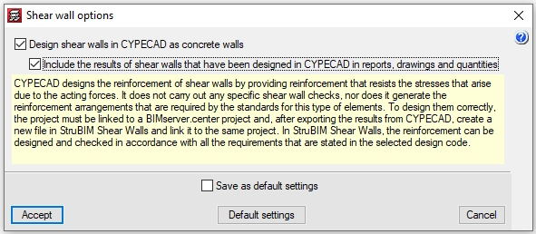
Shear wall options have also been added to "General options". CYPECAD can now design shear walls as concrete walls, regardless of the fact that they will be exported as shear walls to be designed correctly in StruBIM Shear Walls.
If this option is activated, CYPECAD will design the reinforcement of shear walls with a reinforcement that withstands the stresses demanded by the acting forces, although it will not carry out any specific shear wall checks, nor will it generate the reinforcement provisions established by the regulations for this type of elements.
Other improvements and corrections
CYPECAD version 2021.f also features other slight improvements and corrections to the program that may occur in specific situations:
- Improvement in the "For some reinforcement the compliance factor is less than 100%" warning. Walls with a compliance factor lower than the one selected by the user, and walls with a compliance factor lower than 100% are now reported separately.
- In the "Soil-structure interaction" and "Punching" options, the column references are shown if they are active.
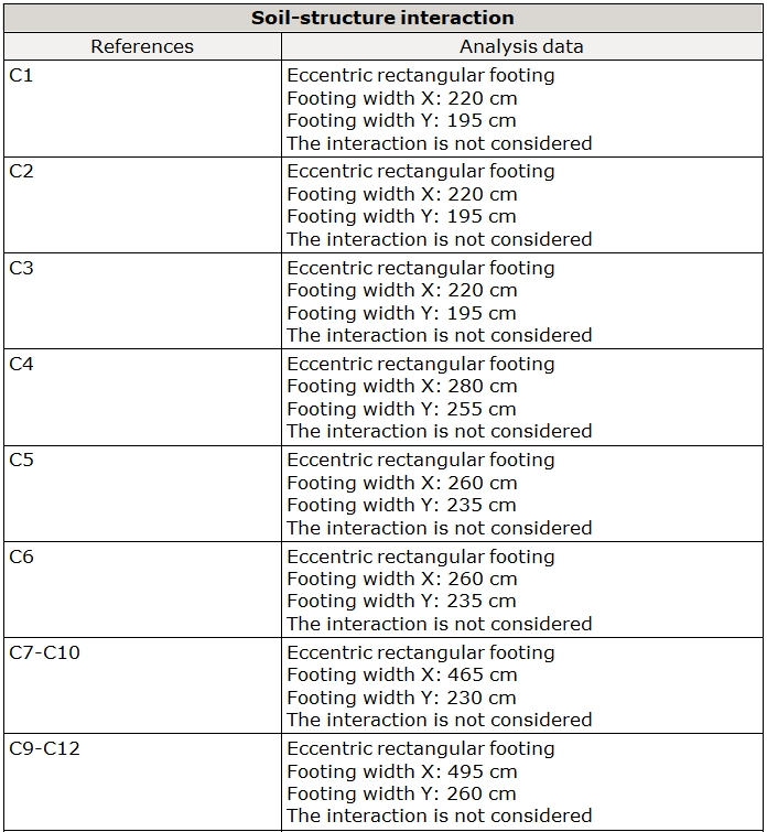
- In the "Soil-structure interaction" section in "Job data report", more information has been added to the strip footings of walls.
- Performance has been improved for several options belonging to property assigning types of menus, such as "Beams - Rigid diaphragm in unconnected beams", "Punching - Lock/Unlock perimeter". When selecting this type of option, the elements are shown in different colours depending on whether or not their properties have to be assigned. Previously, these were displayed after selecting the properties to be assigned.
- The "Panel report" section in the "Job data report" has been improved. Now, the name of the panel is displayed instead of the coordinates.
- An error that arose when analysing jobs that generated result files larger than 2 gigabytes has been fixed.
- Exporting "Hollow core slabs" to "Bills of quantities" has been improved.
- Users can consult the analytical model and the deformed shape of jobs copied to another computer.
- In the "Starts of columns, shear walls and walls by loadcase" section in the "Column, shear wall and wall forces and reinforcement" report, the "Starts" forces are displayed after calculating the structure without generating the reinforcement.
- The text for the "Timber" button in "General data" has been improved so that it is not oversized.
- The display of building elements in 3D view has been improved.
- The text in the initial floor of columns in the "Detailing of columns" drawing has been corrected. This text is shown if "Column detailing along all its height" is selected in the "Type of detailing" option.
- Detecting a column’s fixed point when importing jobs from BIM models or IFC files has been improved.
- Exporting timber element material to IFC files has been improved. Previously, it was exported as "Generic" material.
- Information on foundation elements has been improved in reports and the on-screen query.
- In the "BIMserver.center > Export" option, the data selected in "Deformed shape" is saved for future exports.
- In the foundation element editor, checks are no longer displayed after designing. They can be consulted by clicking on the "Check " button.
- An error has been fixed in the "Load report" section of "Job data report", which could appear if there are poorly defined construction elements on the job site.
- An error that occurred when inserting a strap beam connected to the end of a wall with the same direction has been fixed.
- Entering beams with the "Orthogonal on/off" option activated has been improved. If the second point inserted was close to the axis of a wall, that option may not have been applied.
- The texts for the titles of foundation element checks have been improved. Some checks with certain standards contained strange characters.
- "Additional information" has been restored to the footing check report. In the previous version, this was lost when the report's images were changed.
- An error in the design process for beams with variable depth has been corrected. This occurred in some cases in which the upper plane of the beam was inclined and one of its ends was a secondary beam.
- An error has been fixed in the "3D building view" for certain types of sections in joist floor slabs.
- An error that occurred when retrieving the "Pillar frame" plan has been fixed, this sometimes occurred after deleting stirrups in the column reinforcement editor.
- Distributing stirrups in frames of a single span in overhang has been improved. If one end was a secondary beam, they were always placed up to the external surface of this secondary beam, regardless of the selection made in "Beam Options" > "Reinforcement Arrangement" > "Stirrup Selection" > "Supports on beams".
- An error that occurred with regulation BAEL-91 (R-99) (France) in a job with a "Project situations introduced by the user" selection in "Limit states (combinations)" > "Ground bearing pressures" has been fixed.
- An error in the foundation element editor that occurred after changing the depth, resulting in the equilibrium check not being verified, has been fixed.
- An error in the punching check, that occurred very occasionally when the angle of the column and the panel had almost the same angle, has been fixed. Due to an accuracy error in the processor, it was determined as unequal in this situation.
- An error in the beam frame design process has been fixed in cases where a frame was blocked and, due to a force change, the overhang was modified at one end of the frame.
- An error that arose when entering jobs containing an integrated 3D structure that was not correctly defined has been fixed. From this version onwards, when this happens, a "You must check integrated structure, etc." type of message will be displayed. Normally, this type of error is automatically corrected when editing integrated 3D structures.
- An error in jobs combining both the concrete standard ACI 318-14 and the Ecuadorian NEC-SE-DS 2014 seismic action standard has been solved. From version 2021.f onwards, if the "Criteria of reinforcement by ductility" selection is "None", no criteria according to NEC-SE-DS 2014 will be applied, but seismic requirements according to a D, E, F category for ACI 318-14 will be applied.
StruBIM Steel
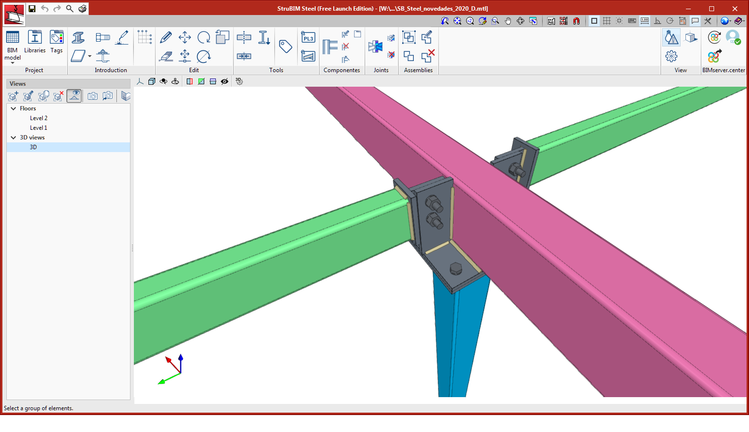
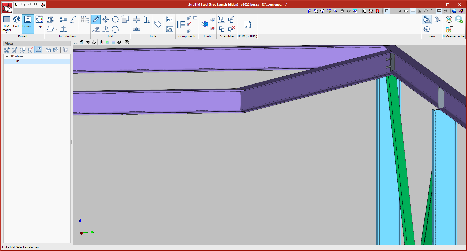
Modelling and analysis of connections using the CYPE Connect Steel program integrated in StruBIM Steel
Version 2021.f implements a new tool for modelling and analysing connections, CYPE Connect Steel.
CYPE Connect Steel also operates as an independent program. More information on CYPE Connect Steel.
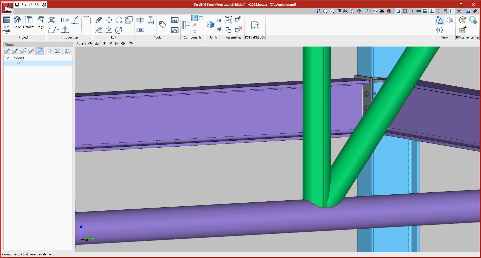
CYPE Connect Steel, as an integrated tool in StruBIM Steel, allows users to freely define connections between sections. From a range of sections, users establish the layout of the different elements that make up the connection (plates, welds, bolts, anchors, additional sections). Additionally, this tool also carries out an analysis of the connection using the finite element method. It offers the option of obtaining both the structure detailing as well as the justification of the regulatory compliance of the adopted connections.
To add a new joint, users must select the "New" option in the "Joints" menu. Next, they must select the sections used for the joints, and click on the right mouse button.
These joints may be edited using the "Edit" option in the "Joints" menu, by selecting the desired connection.
New types of predefined connections
Connections between hollow sections
- One main hollow section and two secondary ones
In this connection, the first secondary hollow section is cut by the main hollow section. The third hollow section is cut by the two previous ones.
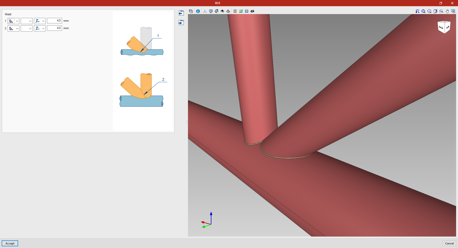
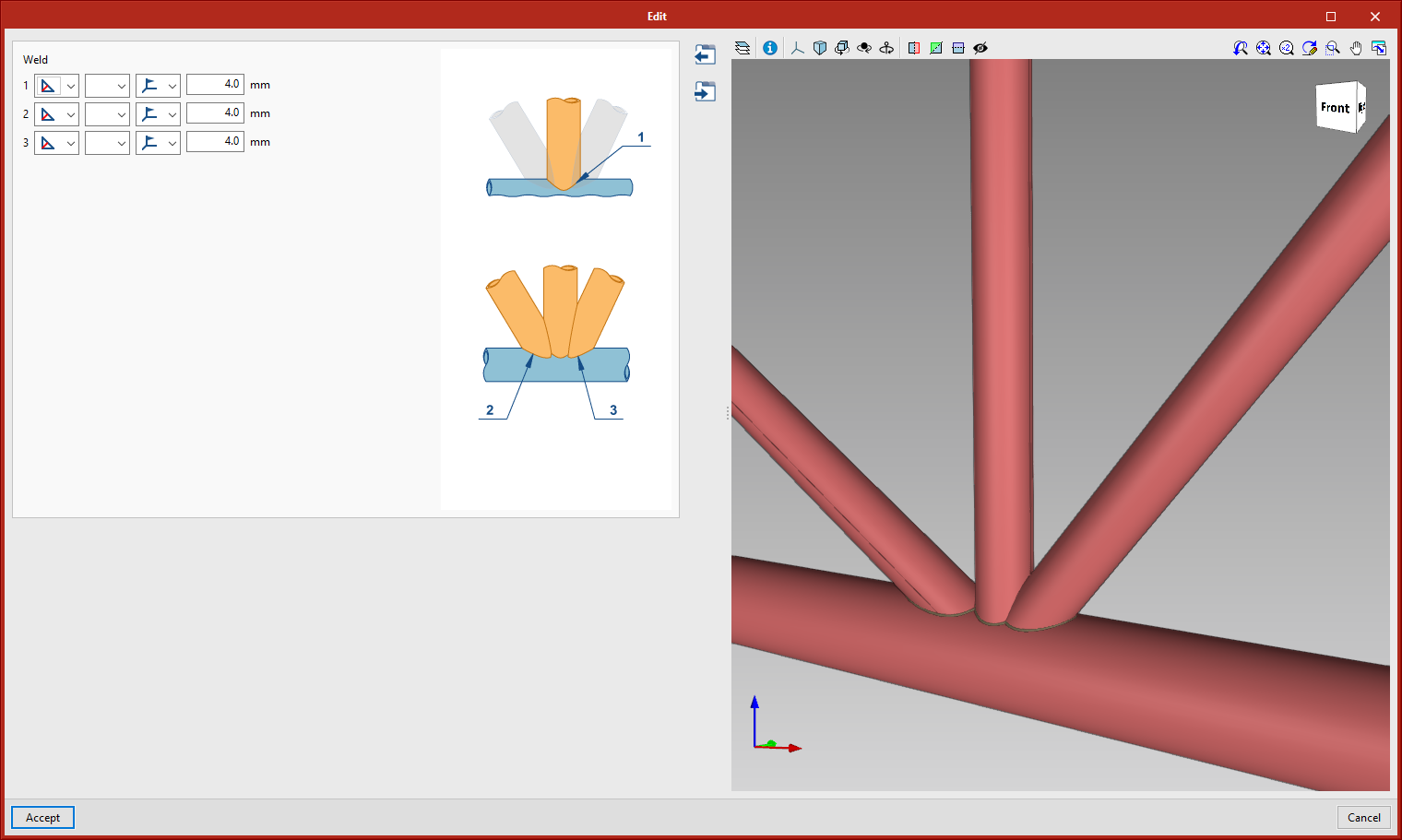
- One main hollow section and three secondary ones
In this connection, the first secondary hollow section is cut by the main hollow section. The third and fourth hollow sections are cut by the main hollow section and the first secondary one.
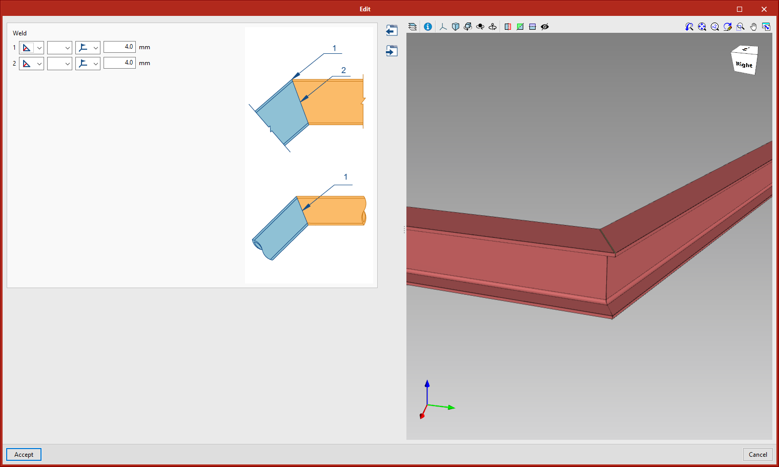
Connection in the "Splices" section
This connection allows butted connections between sections. The section types admitted are rolled I section, rolled U section, circular hollow section, and rectangular hollow section.
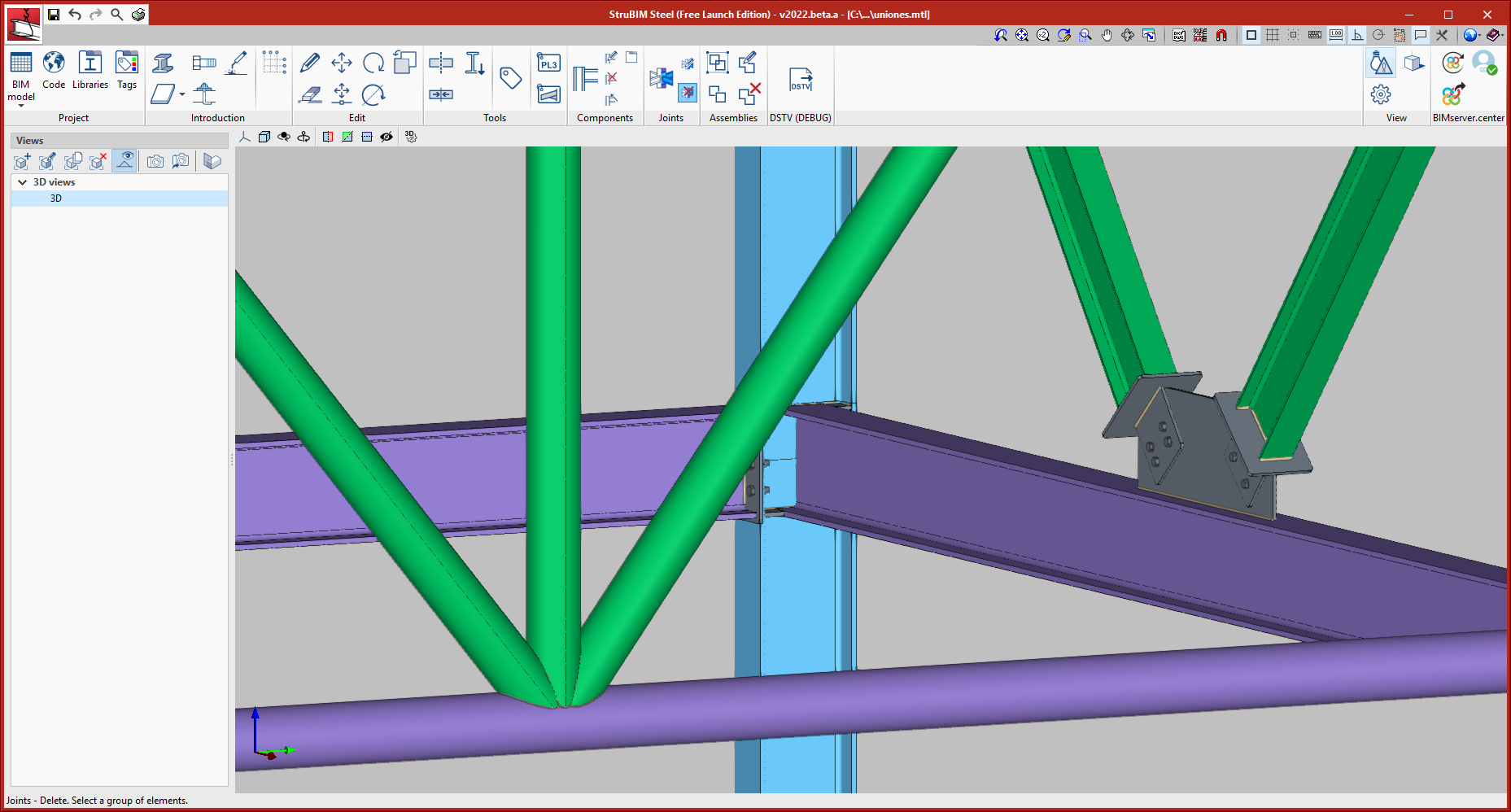
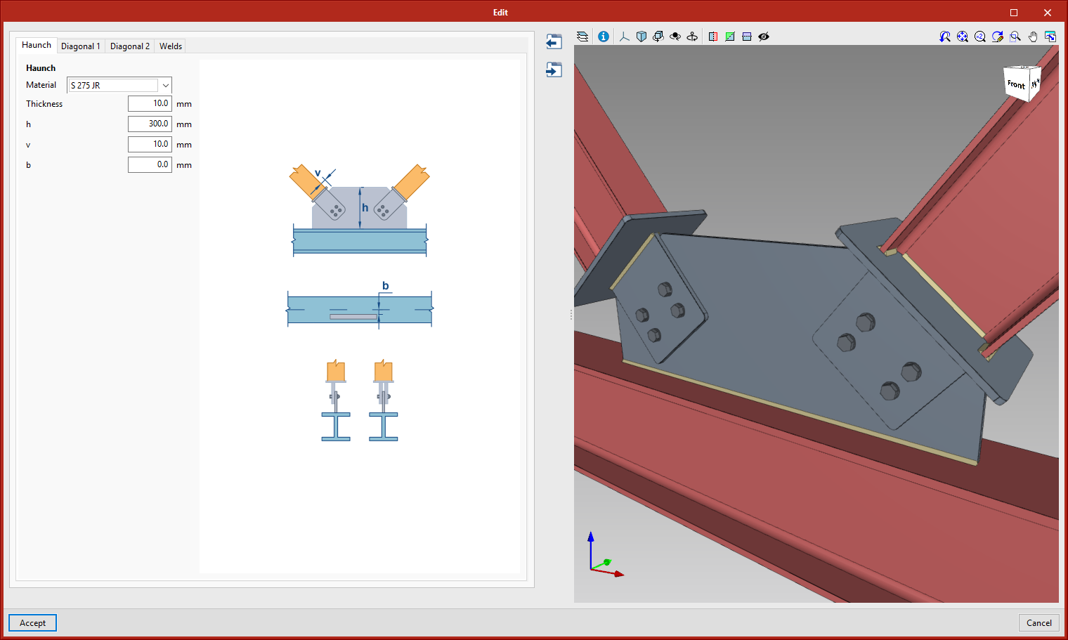
Bolted connections between diagonal sections and haunches
This connection is found in the "Bracing" category. It allows two diagonal sections to be joined to a main section. The main section allows rolled I sections, simple U sections, circular and rectangular hollow sections, and even welded I sections and welded variable sections. As for diagonal sections, they allow I sections of rolled steel, and circular and rectangular hollow sections.
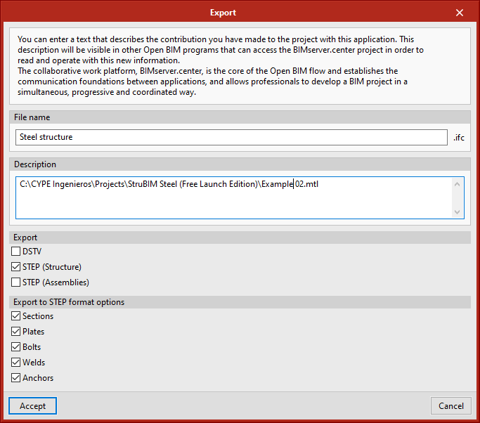
STEP format export options
In version 2021.e, the exporting to STEP format was implemented, this version exported sections and boards. Version 2021.f has implemented the exportation of bolts, welds, and anchors. Also, users are given the option of selecting the types of elements they wish to export.
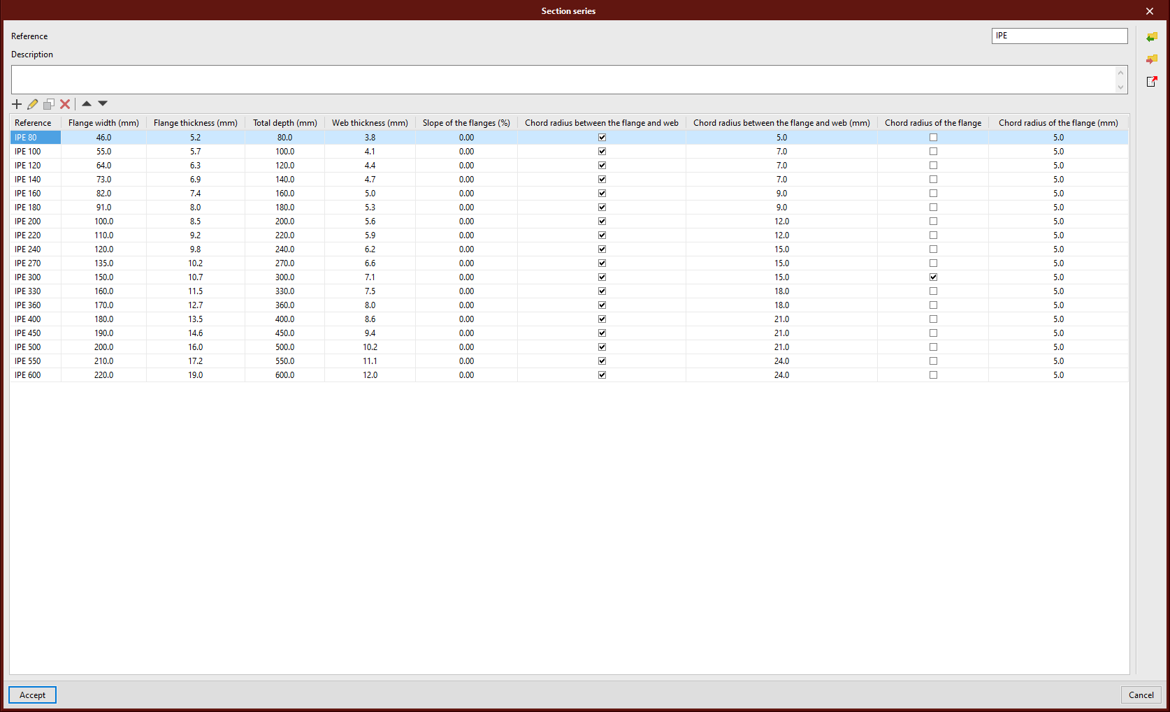
Libraries in table mode
The materials and section libraries have been modified. Now they are represented and edited in table mode. With this upgrade, it is easier to add or edit the library by pasting from the Excel table clipboard.
StruBIM Shear Walls
New reports
The following reports have been added to version 2021.f of StruBIM Shear Walls:
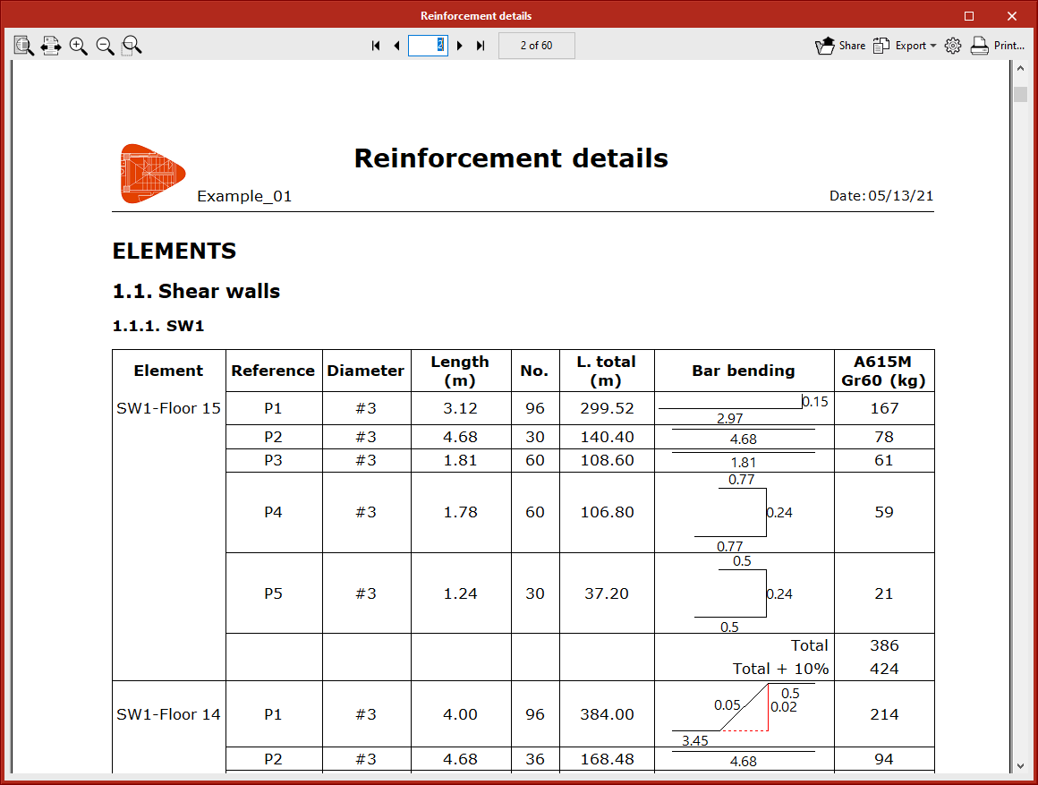
- "Reinforcement details" report
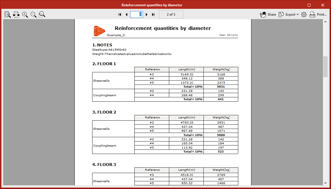
- "Reinforcement quantities by diameter" report
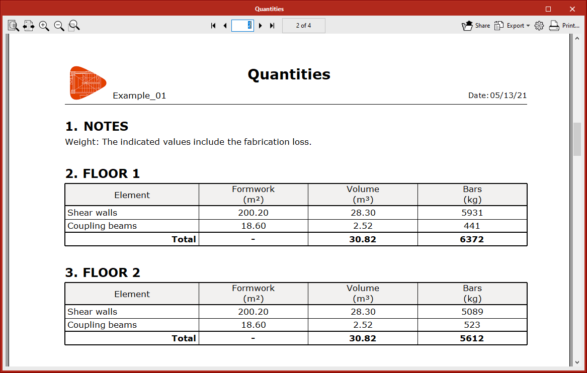
- "Quantities" report
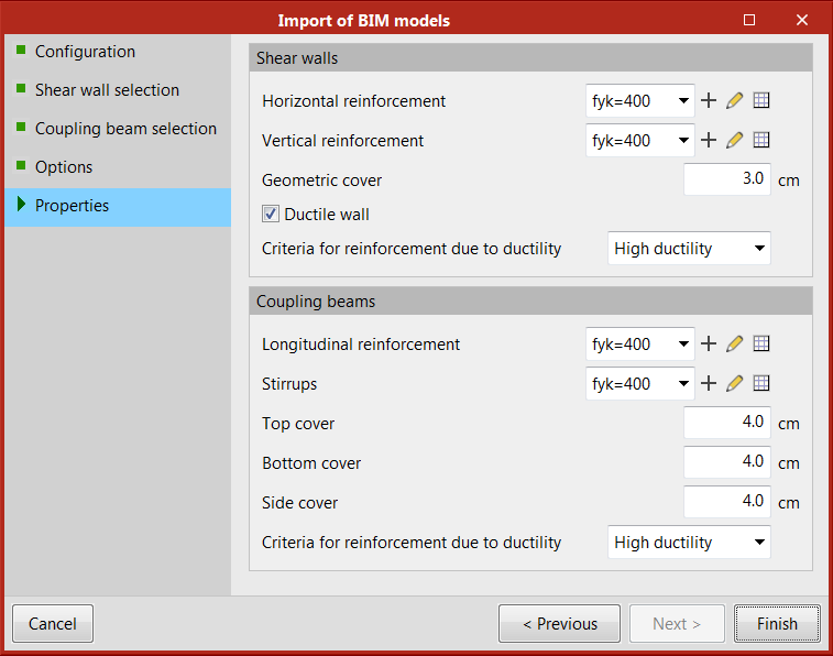
Selecting materials during the import of a BIM model
In the BIM model data import assistant of a project located on the BIMserver.centre platform, the option for selecting the type of steel and reinforcement cover has been added. The type of concrete is directly assigned to the walls and beams, so it matches the one defined in the source program.
Other improvements and corrections
Version 2021.f of StruBIM Shear Walls also includes other slight enhancements and corrections of errors that may appear on rare occasions:
- The distribution of vertical reinforcement bars in shear walls has been improved.
- The distribution of crossties in shear walls and coupling beams has been improved.
- The design process can now be cancelled.
- An error during the job update, which occasionally occurred after a shear wall had been added in CYPECAD, has now been fixed.
- Generating intervals in "Segment classification" if there are several unconnected segments in a section with the same direction has been improved.
- Checking transverse crossties in Eurocode type regulations has been improved. Previously, in some cases, not every crosstie was considered.
- The default value for "Minimum number of layers" in "Reinforcement layout criteria" has been changed to 2.
CYPELEC PV Systems
Improvements to the Energy pre-designer
In the 2021.f version, a series of improvements have been implemented in the energy pre-designer to facilitate its use and increase its performance:
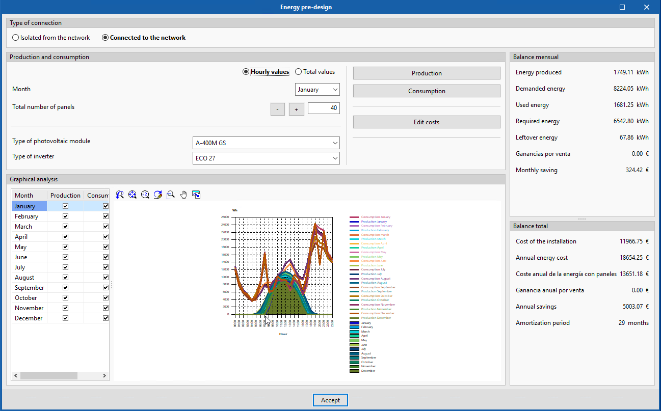
- Unification in one single pre-designer
Grid-connected and off-grid installations have been unified in the same pre-designer. Now, we can select the system type we wish to pre-design in the very same window.
- Introduction of production and consumption values
In the "Production and consumption" section of the energy pre-designer panel, two options have been enabled to introduce the production and consumption values of the installation.
Now, it is possible to introduce them as "Hourly values" or as "Total values" for both grid-connected and off-grid installations.
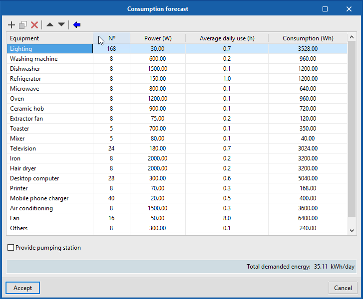
When we choose to indicate total production and consumption values, the consumption for each month can be defined by their total daily consumption or by selecting the "Consumption forecast" option, which allows you to define the power and average daily use of different equipment. For the consumption forecast it is possible to import some usual equipment consumption values.
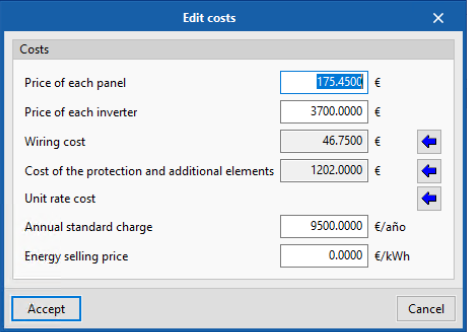
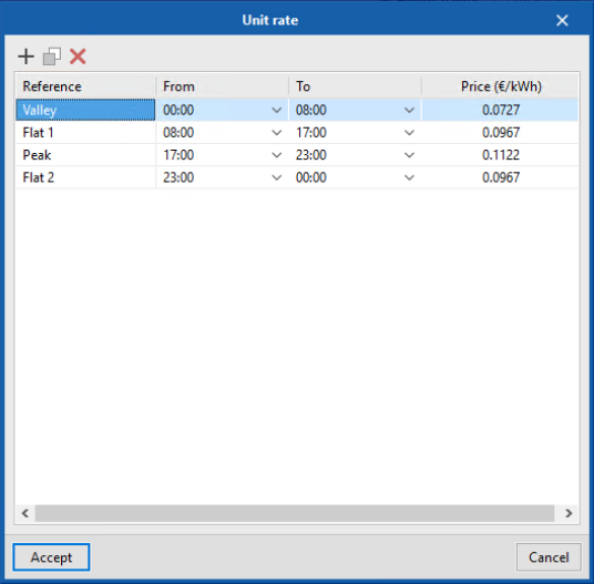
- Edit costs
In Edit costs, the "Unit rate cost" per hourly period has been added, as well as the "Annual standard charge" and the "Energy selling price", which allows us to perform a more detailed economic analysis.
- Graphical information
Depending on the option chosen for defining the production and consumption values (hourly or total), the graphical analysis shown in the pre-designer is represented by a line graph of production and consumption per hour for each month, or by a bar graph of energy demanded and produced per month.
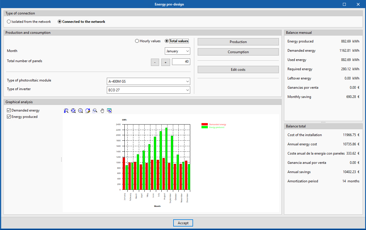
- Total and monthly balance
In the energy pre-designer panel, the number of offered results has been increased. Now they are organized in a monthly and total balance in which all the costs of the installation, the monetary savings, and the estimated amortization period for the installation are listed.
CYPETEL Schematics
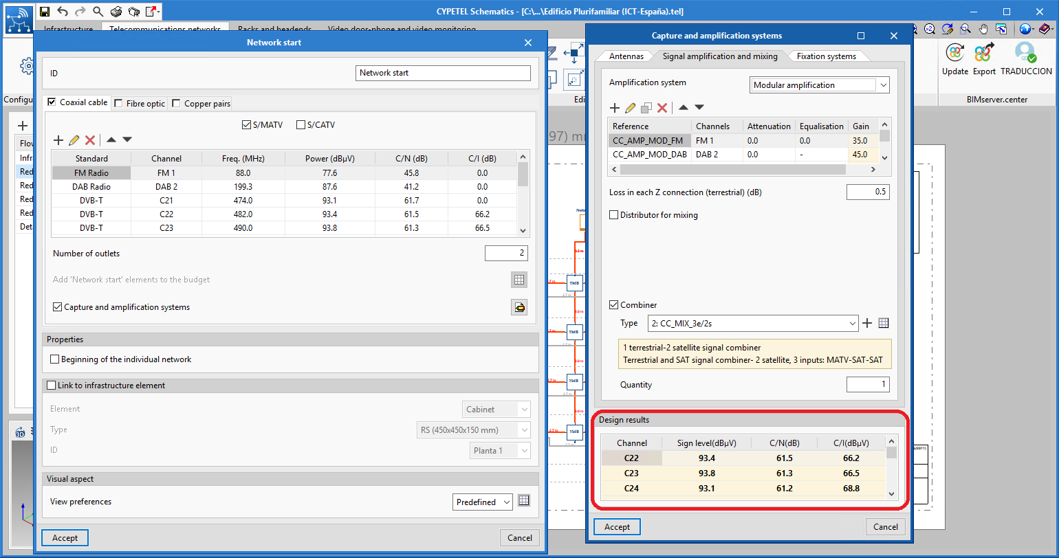
Design of coaxial network headends
To create the different types of new equipment in the program, which were implemented in CYPETEL Schematics in the previous version (2021.e), the technical data that is used to design the installation must be entered.
The "Capture and amplification system" option within the "Network start" element incorporates the design of the signal level and C/N from the antennas to the output of the headend. Once the design process has finished, the values that have been obtained can be transferred to the "Network start" channels.
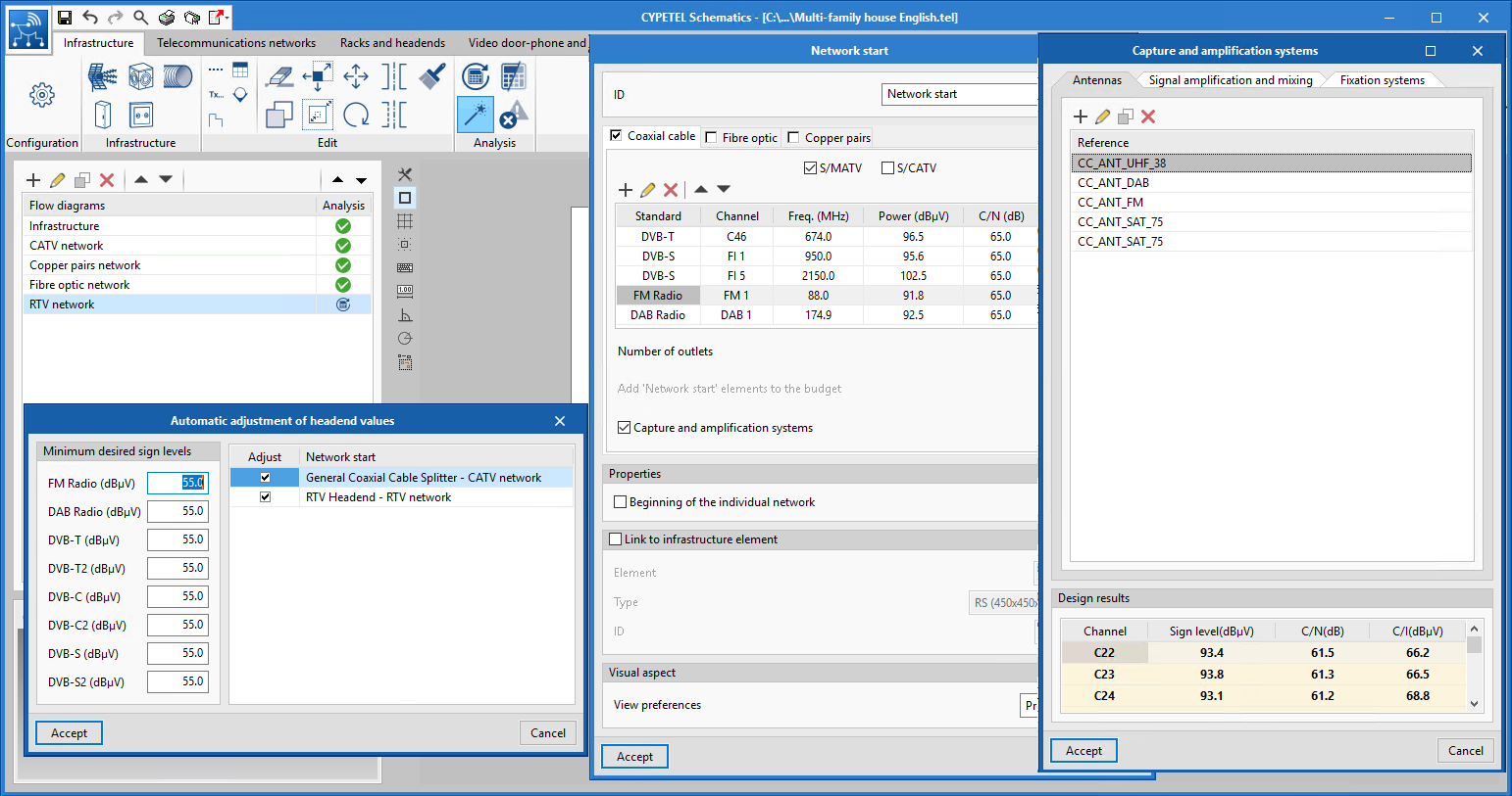
Automatic gain adjustment of the headend
Until now, the "Automatic adjustment of headend values" tool only modified the signal levels of "Network start" channels. Now, it also adjusts the gain of the "Capture and amplification system" headend amplifiers to meet the requirements of the "Network start".
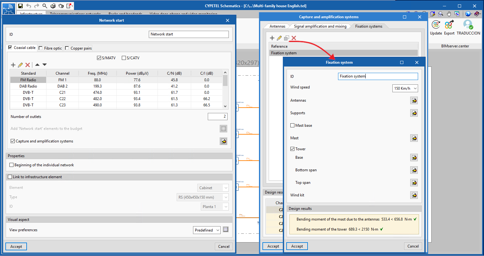
Analysis and check of signal reception system forces
The program calculates and checks the forces that the antenna support elements (masts and towers) must withstand, in accordance with the user-defined layouts. The program will check and compare the resultant moment with the maximum moment resistance of the support elements, and will warn users if there are any incompatibilities.
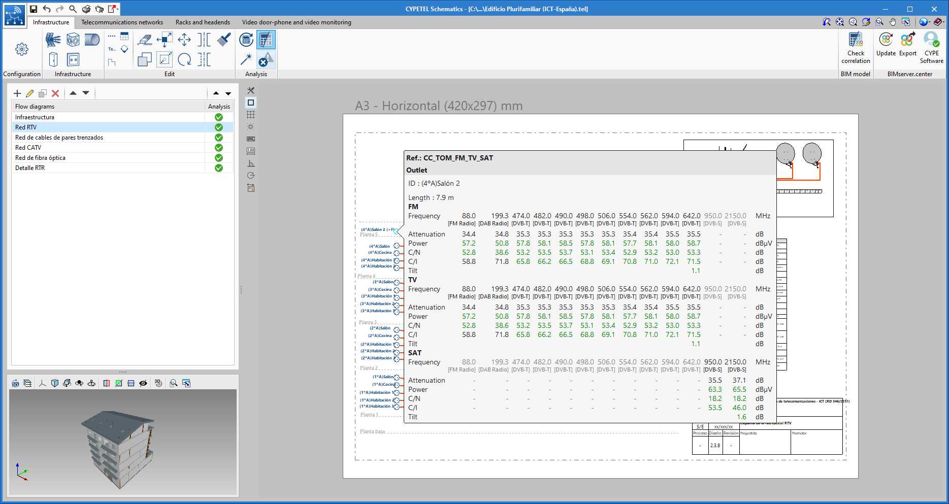
Analysis of the Carrier to Intermodulation (C/I ratio)
As of version 2021.f, CYPETEL Schematics allows users to verify values of the Carrier to intermodulation (C/I), a parameter that identifies signal distortion due to the non-linearity of devices (such as amplifiers). The program incorporates both the analysis of this ratio as well as the possibility of carrying out limit value checks.
CYPEHVAC Radiant Floor
Thermo-active slab design
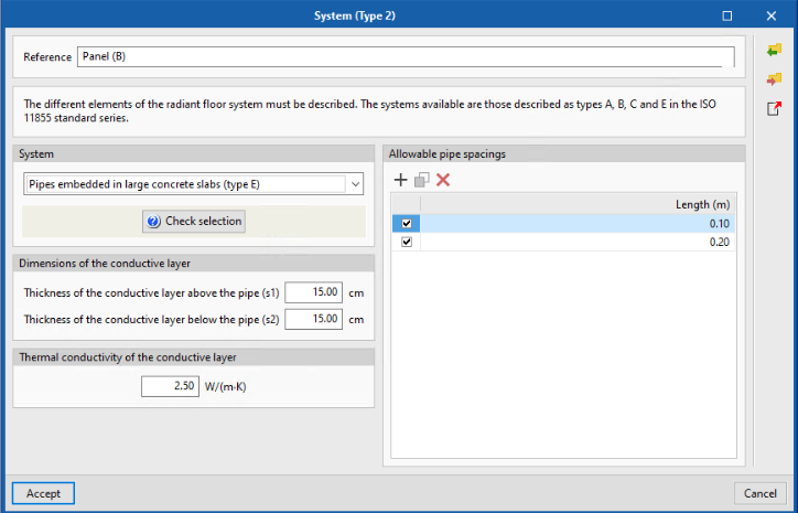
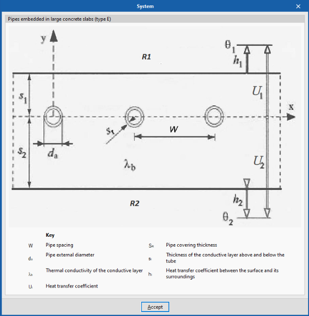
Starting with version 2021.f, CYPEHVAC Radiant Floor (software for modelling and design of radiant floor installations) integrates the design of the "type E" radiant floor system defined in International Standard ISO 11855. This radiant floor system has the pipes embedded in large concrete slabs. It is also known as "active thermal slab system" or "TABS" (Thermally Active Building Systems).
This system combines the more traditional A-C and B types which are already implemented in the program.
CYPEHVAC Radiant Floor allows the setting of the characteristic parameters necessary to correctly design the "TABS" system.
In addition, using the imported geometric model of the BIM project hosted on the BIMserver.center platform, or by means of the user-defined floors, CYPEHVAC Radiant Floor determines the system contributions to both the upper spaces (above the floor slab) and the lower spaces (defined under the floor slab or on the floor below).
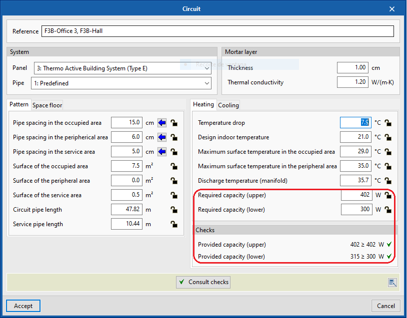
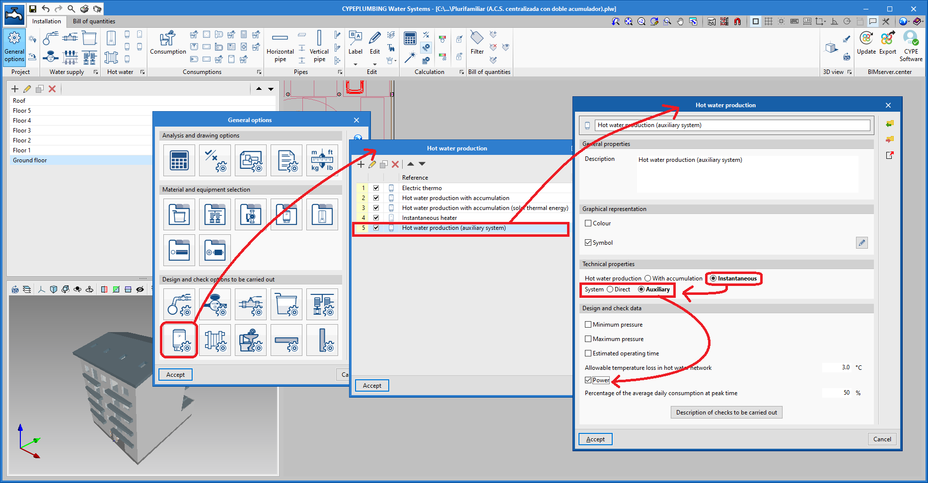
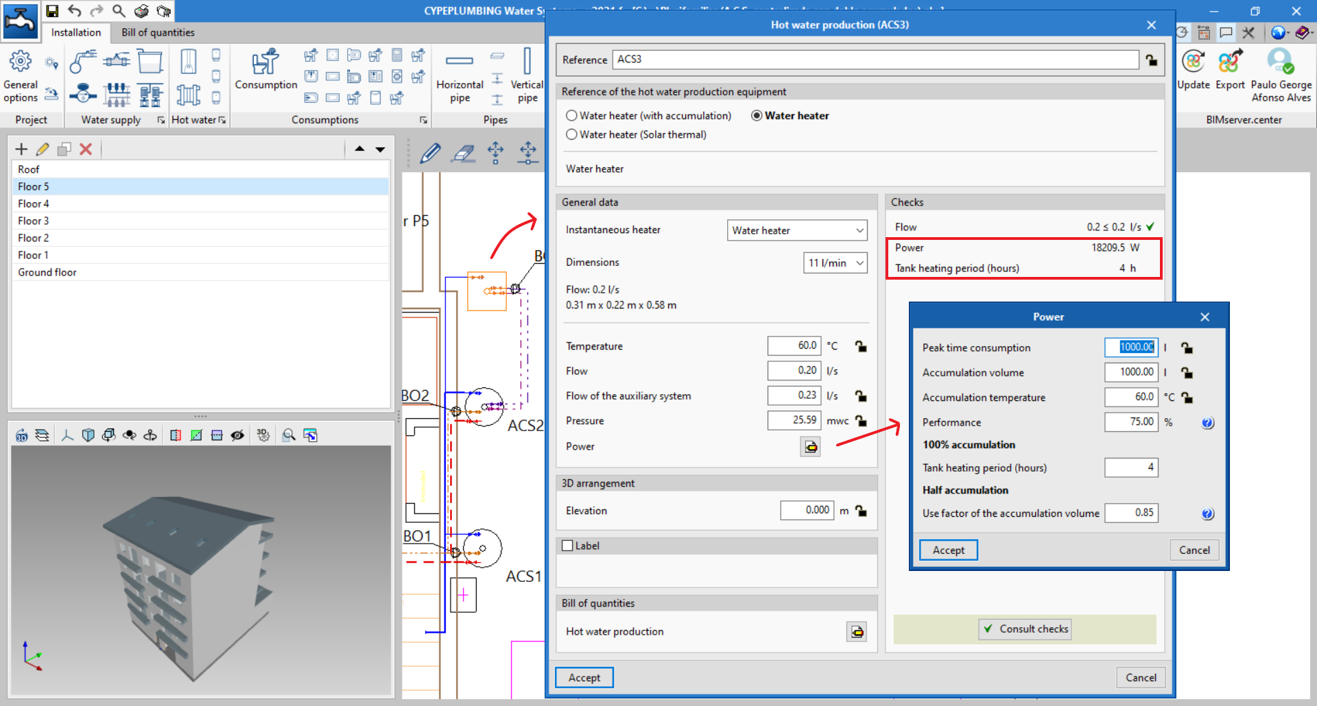
CYPEPLUMBING Water Systems
Capacity calculation of instantaneous DHW production equipment in direct and indirect systems
Capacity calculation of instantaneous DHW production equipment for direct consumption supply systems, or supply systems using storage tanks.
For both the direct and auxiliary systems, everything will be managed from the general data in the program.
When the outline for the installation of a DHW production group is carried out, users will receive the information necessary for establishing its power.
Users must enter the performance of the DHW production system (a performance that must consider exchange, accumulation, distribution, and recirculation losses).
For installations where 100% of the demand is accumulated, it is only necessary to add the hours in which the heating of this accumulation is stipulated. For installations with less than 100% accumulation demand, a use factor of the accumulation volume must be defined. This factor depends on the geometry (slenderness) and the number of storage tanks, as inside the tanks is a mixed area of hot and cold water, in which the temperature is lower than that in use so that the tank is equivalent to one with a lower capacity.
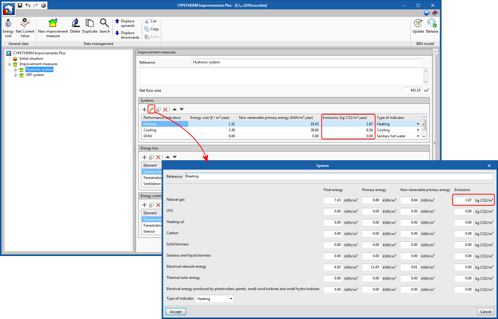
CYPETHERM Improvements Plus
CO2 Emissions
In the Systems section of each analysis scenario, a new column has been added to account for CO2 emissions due to energy consumption of the different technical services of the building.
The total CO2 emissions of each scenario are collected in the Improvement measures analysis list with the purpose of being able to compare their values in the different proposed cases.
The CO2 emissions associated with each service and energy vector used in the building can be imported from the IFC files generated by the CYPETHERM programs with EnergyPlus engine (CYPETHERM EPlus, CYPETHERM HE Plus, CYPETHERM RECS Plus and CYPETHERM Fujitsu).
CYPETHERM LOADS

Importing insulation products by Grupo Valero
From version 2021.f, users can import the thermal parameters of insulation products by Grupo Valero into the configuration of a multi-layered construction system in CYPETHERM LOADS. In the layer definition panel, the Grupo Valero icon now appears on the right-hand side of the window. By clicking on it, users can access the manufacturer's database for an updated list of their available insulation products. Users can browse the products in order to select those appropriate and, by accepting the panel, its properties will be imported into the corresponding application.
If the construction systems in Open BIM Construction Systems have already been linked, it will not be necessary to re-assign any material-related data in the analysis tools.
Importing the construction systems by Grupo Valero will also be available, as of this versión, in Open BIM Construction Systems.
Although the Grupo Valero icon in the layer definition panel is displayed in every language the application is installed in, the manufacturer's insulations that appear correspond to the products supplied by Grupo Valero in Spain.
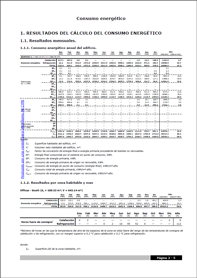
CYPETHERM EPlus
New results for lighting energy consumption and CO2 emissions
New calculation results have been added to the Consumption report:
- In table "1.1.1 Annual energy consumption of the building" in the "Electricity" section, the final and primary energy consumption for lighting is shown, calculated from the definitions made in the spaces.
- In table "2.2 Conversion factors", the table shows the final and primary energy consumption results and CO2 emissions itemized by the different energy vectors used in the building.
CYPETHERM programs with EnergyPlus engine (CYPETHERM EPlus, CYPETHERM FUJITSU)
Exporting building CO2 emissions result to CYPETHERM Improvements Plus
CYPETHERM programs with EnergyPlus engine export the CO2 emissions results itemized by building technical services and energy vectors. This information has been added to the IFC file that the program generates upon clicking on the Improvement measure button. This file can be imported into CYPETHERM Improvements Plus, which as of version 2021.f includes a section to define the CO2 emissions associated with each technical service in the building.
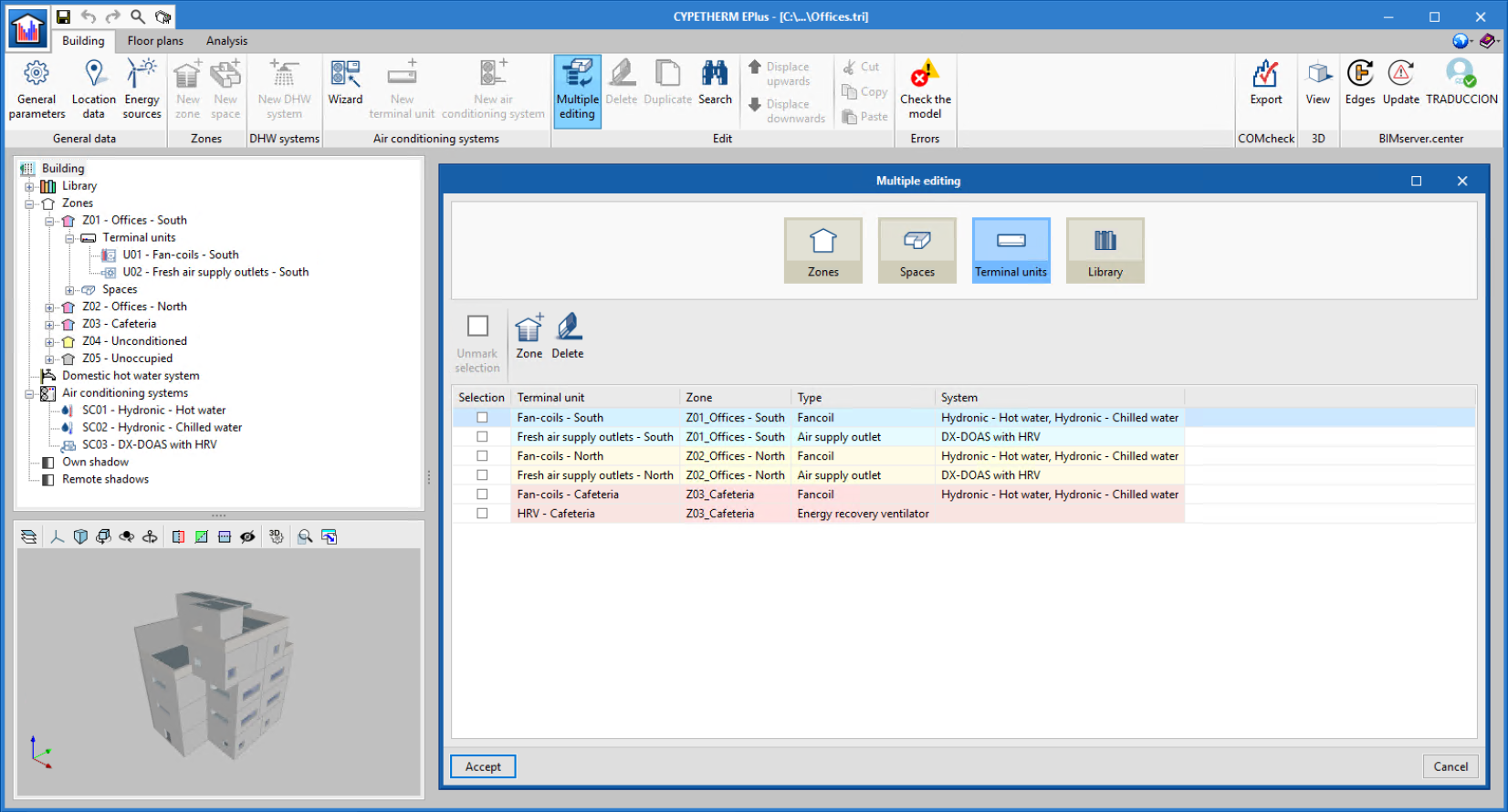
Display of air conditioning systems connected to terminal units
In the building tab, after clicking on the "Multiple editing" button, in the "Terminal units" section, the "System" column has been added which shows the air conditioning system(s) connected to each terminal unit defined in the building zones. Collecting this information in a single window allows for quicker review of the air conditioning systems connections.
Arquimedes
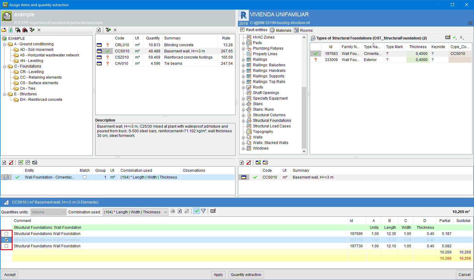
Bill of quantities of Revit models
Omit element quantities
It is possible to mark the elements that the user does not want to measure in a given item. This tool supplements other existing tools to filter and define what will be measured. The possibility to mark elements to avoid quantities is available once a Revit element has been linked to an item and the appropriate extraction combination has been selected or created. In the quantities detail table that is created, the user can mark the elements of each line that they do not want to measure by means of a selection box located at the beginning of each quantities detail line.
Open BIM Cost Estimator
Cost database update
The cost database that is used by the application to establish the construction cost estimate has been revised. Projects that have been carried out using earlier program versions will be updated automatically when they are opened with the 2021.f version.
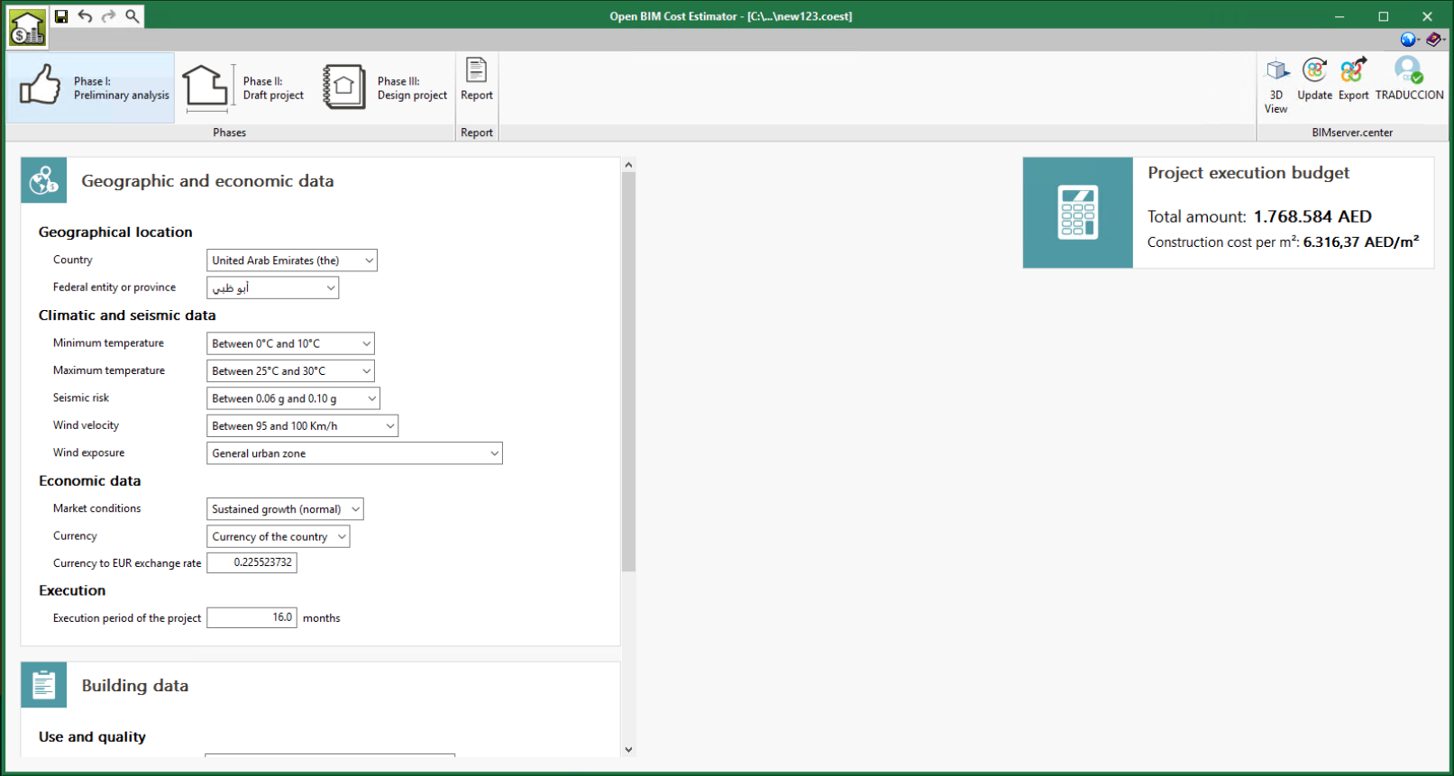
New countries
The following countries have been added, together with their federal entities or provinces, in the geographic and economic data of "Phase I. Preliminary analysis":
- Saudi Arabia
- United Arab Emirates
- Israel
- Kuwait
- Philippines
- Korea (Republic of)
- Qatar
- China
- Hong Kong
- India
- Japan
- Macau
- Pakistan
- Singapore
- Taiwan
- Malaysia
- Denmark
- Argentina
- Ecuador
- Peru
- Honduras
- Bolivia (Plurinational State of)
- Paraguay
- Guatemala
Open BIM Quantities and applications with the Bill of Quantities tab
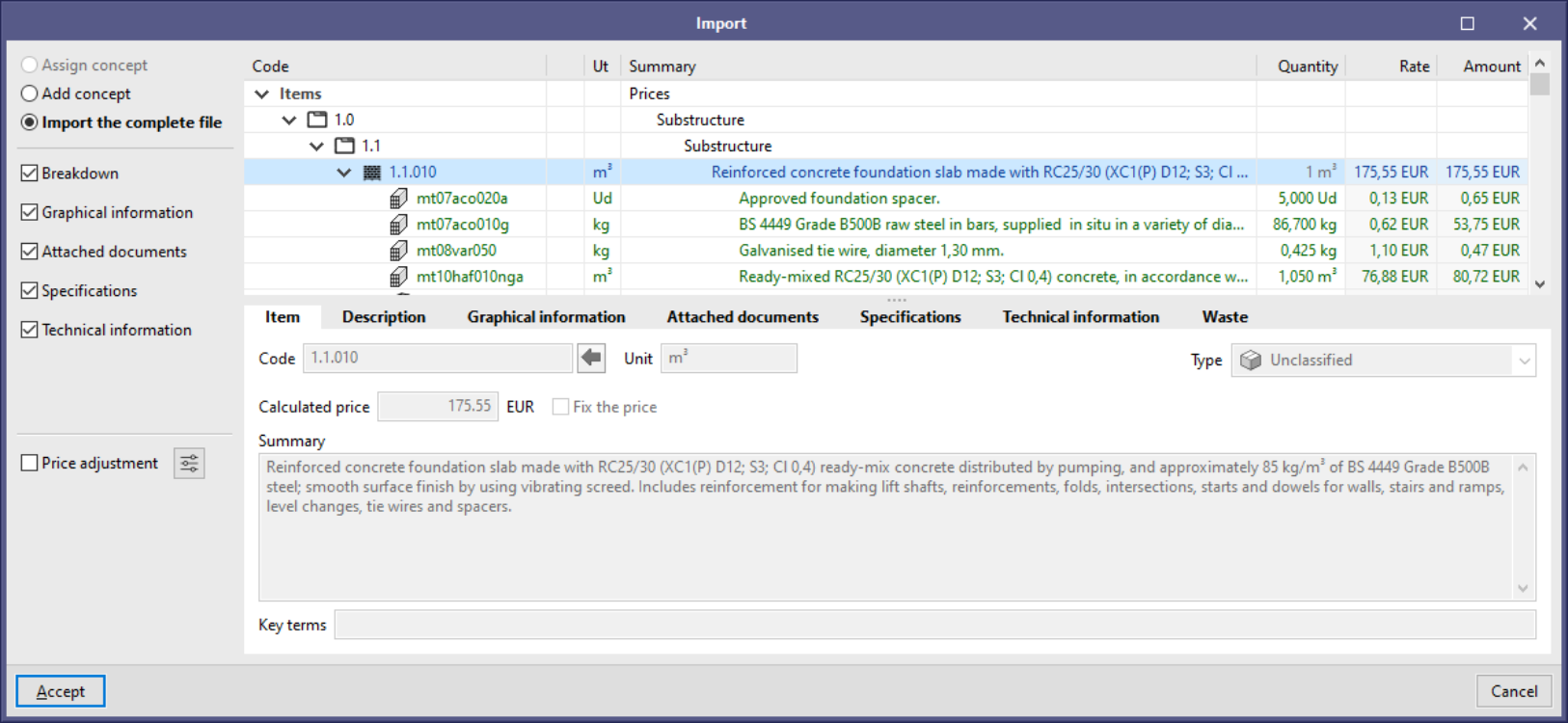
Import complete FIEBDC-3 (.bc3) files via "drag & drop"
From version 2021.f onwards, when a FIEBDC-3 (.bc3) file is dragged to the project’s price table or cost database, the "Import the entire file" option is available. When selecting this option, every concept in the file will be included instead of just single concepts, as is the case with "Assign concept" and "Add concept".
Open BIM Quantities
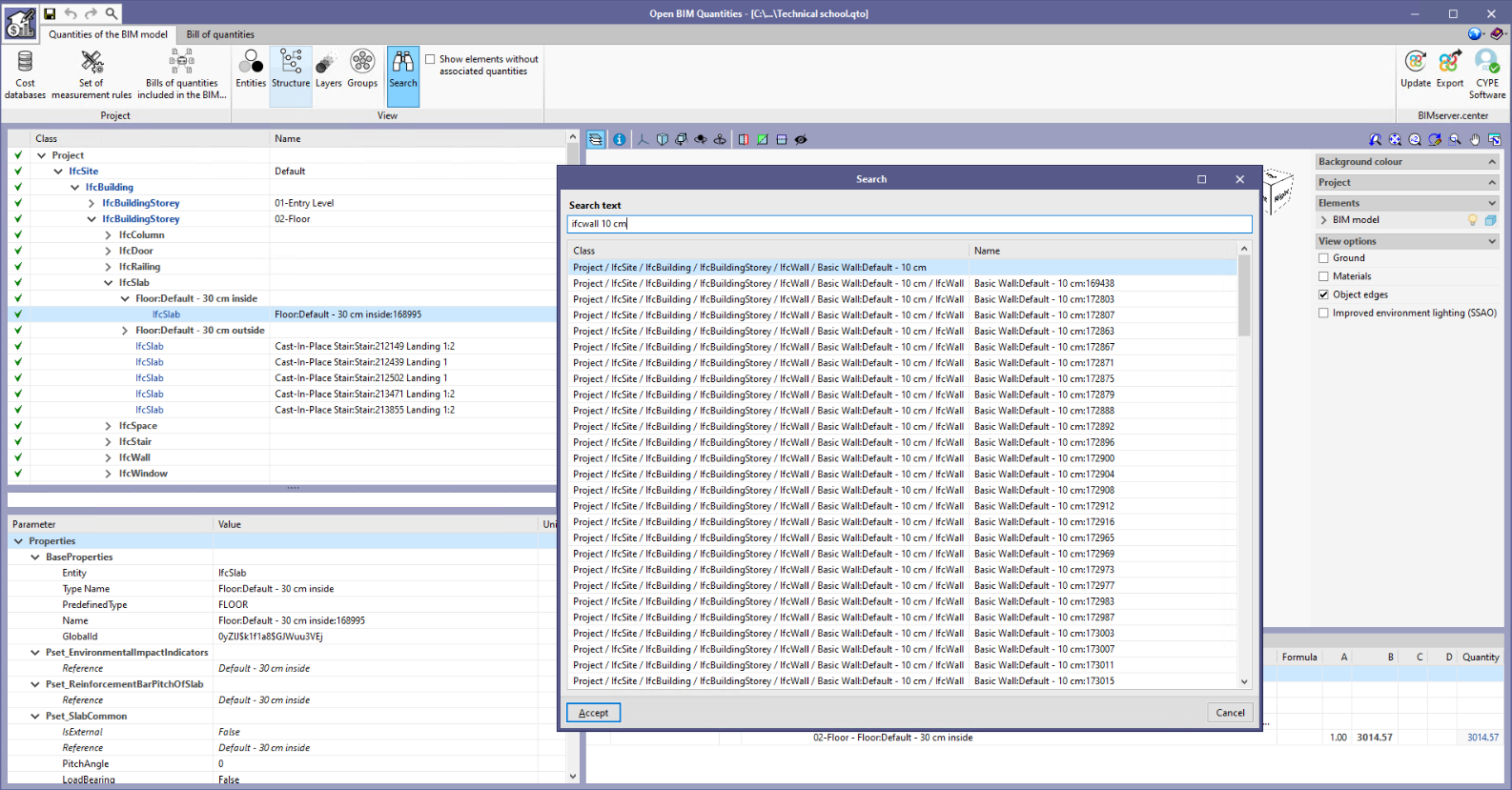
"Search" tool in the "Quantities of the BIM model" tab
A "Search" tool has been added to the "Quantities of the BIM model" tab in the "Open BIM Quantities" toolbar. This new feature allows users to locate elements in the BIM cost breakdown structure quickly by means of their "Class" and "Name".
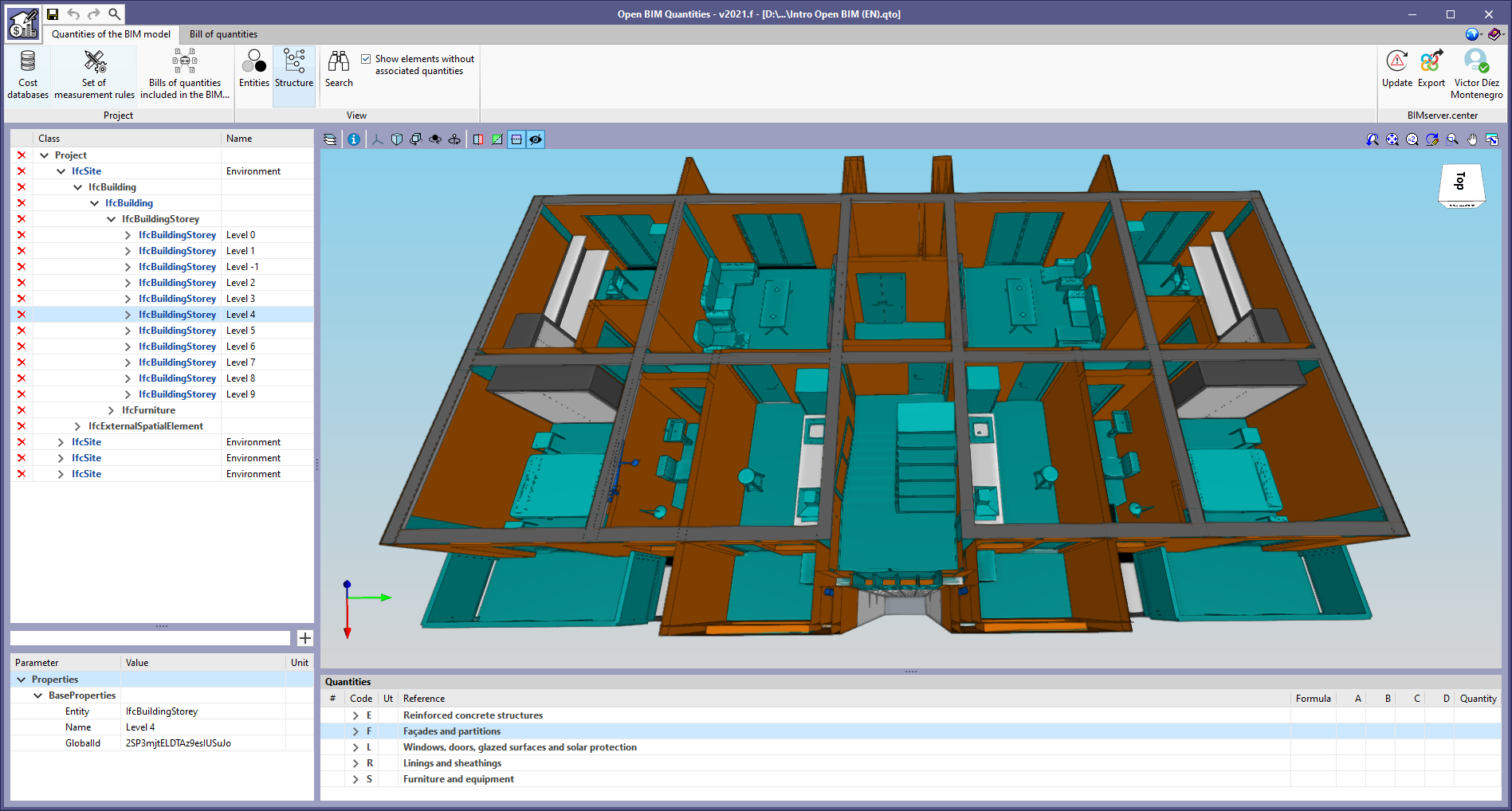
View options of the BIM model
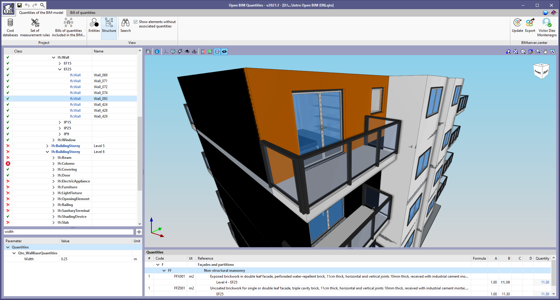
As of version 2021.f, Open BIM Quantities offers two different ways of viewing the BIM model’s cost breakdown structure in the "Quantities of the BIM model" tab. Up until now, elements have always been organised according to the IFC entity they belong to (IfcWall, IfcSlab, IfcSpace, etc.). In this update, the "View" group of options has been added to the application toolbar with two buttons: "Entities" and "Structure". The first one shows the BIM model’s cost breakdown structure in the same way as the previous versions, i.e. it groups the elements according to their IFC entity reference. The second one allows users to organise the breakdown structure based on the project’s spatial structure.
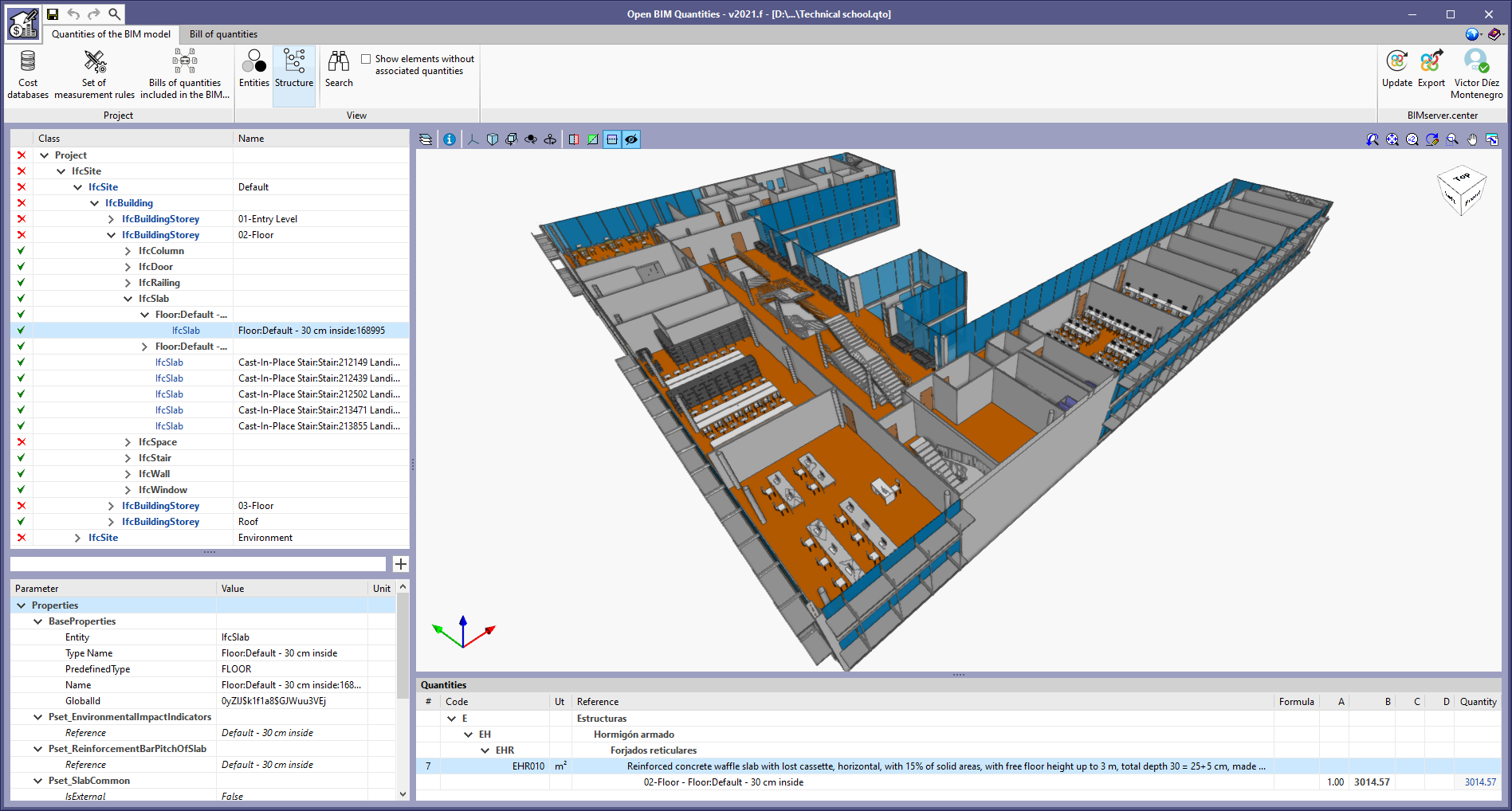
According to the IFC standard, spatial structures are used to provide a hierarchical distribution of models with the aim of organising construction projects. A project’s spatial structure can define as many decomposition levels as necessary for the project.
The elements of the spatial structure are as follows:
- Site ("IfcSite")
- Building ("IfcBuilding")
- Storey or floor ("IfcBuildingStorey")
- Space ("IfcSpace")
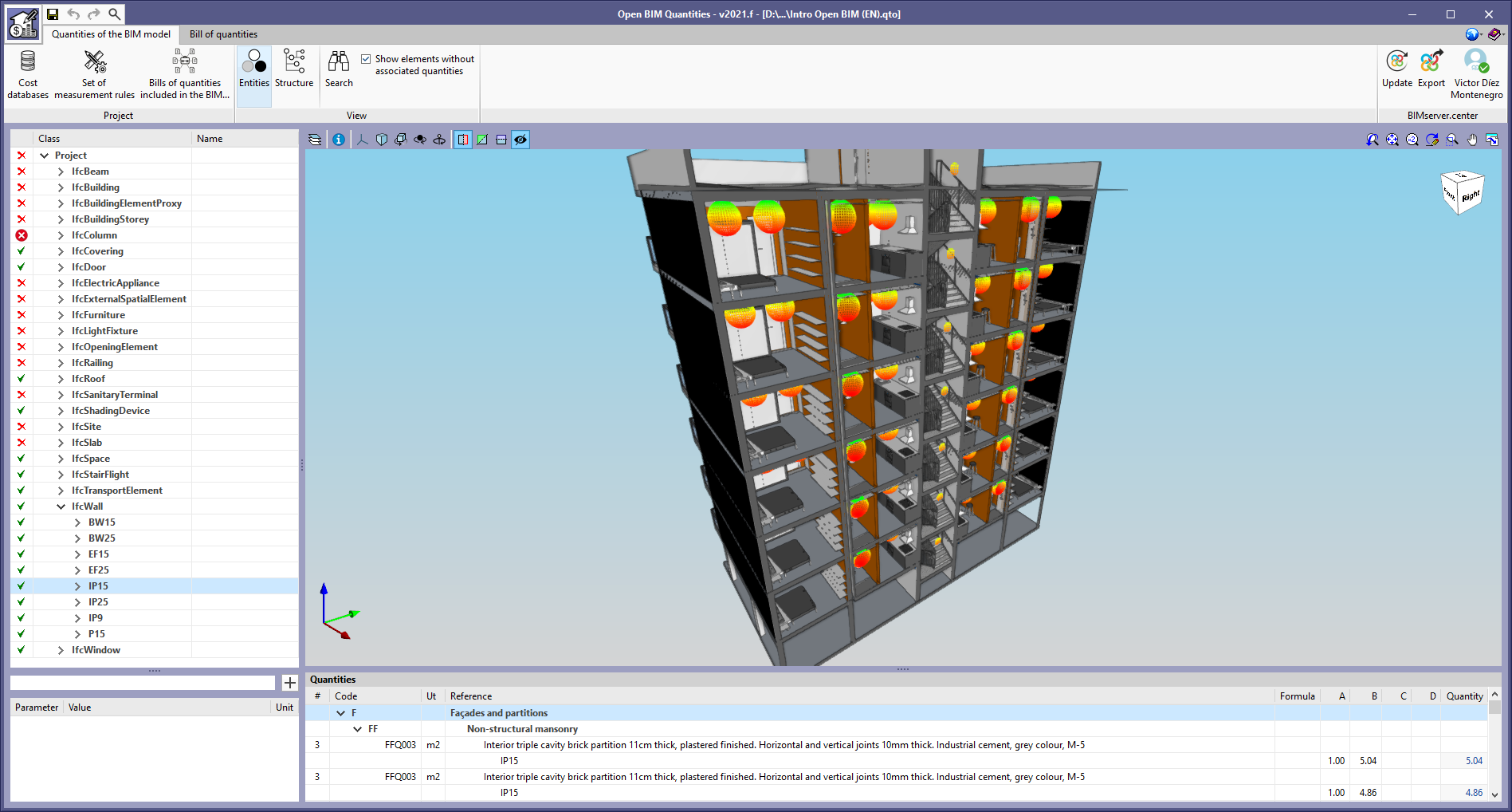
Reading of the properties and quantities associated with the type
From version 2021.f onwards, "Open BIM Quantities" can incorporate the sets of properties and quantities defined at type level, based on the IFC standard specification. All model components belonging to the same type assume the properties and quantities specified at type level. However, it is possible that element-level definitions may invalidate these type-derived properties and quantities. The different combinations are shown in the list of parameters associated with the model component as follows:
- If the property or quantity is defined at a component level only, the property or quantity’s reference and value are displayed in plain text.
- If the property or quantity is defined at type level, the name of the property or quantity and its value are displayed in italics.
- If the property or quantity is defined at type level, but is different at component level, the name and value at component level are shown in plain text while the type name and value are shown in italics and strikethrough.
Reading of complex quantities and properties of IFC files
As of version 2021.f, "Open BIM Quantities" can read complex properties and quantities. In the IFC standard, complex properties ("IfcComplexProperty") allow users to define a subset of properties as a single "property" entry within a set of properties associated with an element of the BIM model. This function is the same for physical complex quantities ("IfcPhysicalComplexQuantity").
Complex properties and quantities are displayed in the list of parameters associated with the BIM model component in the following format:
[Property reference/complex quantity]. [Property reference/simple quantity]
Complex properties and quantities can be used in the rules of measurement for selecting BIM model elements and defining the generated items.
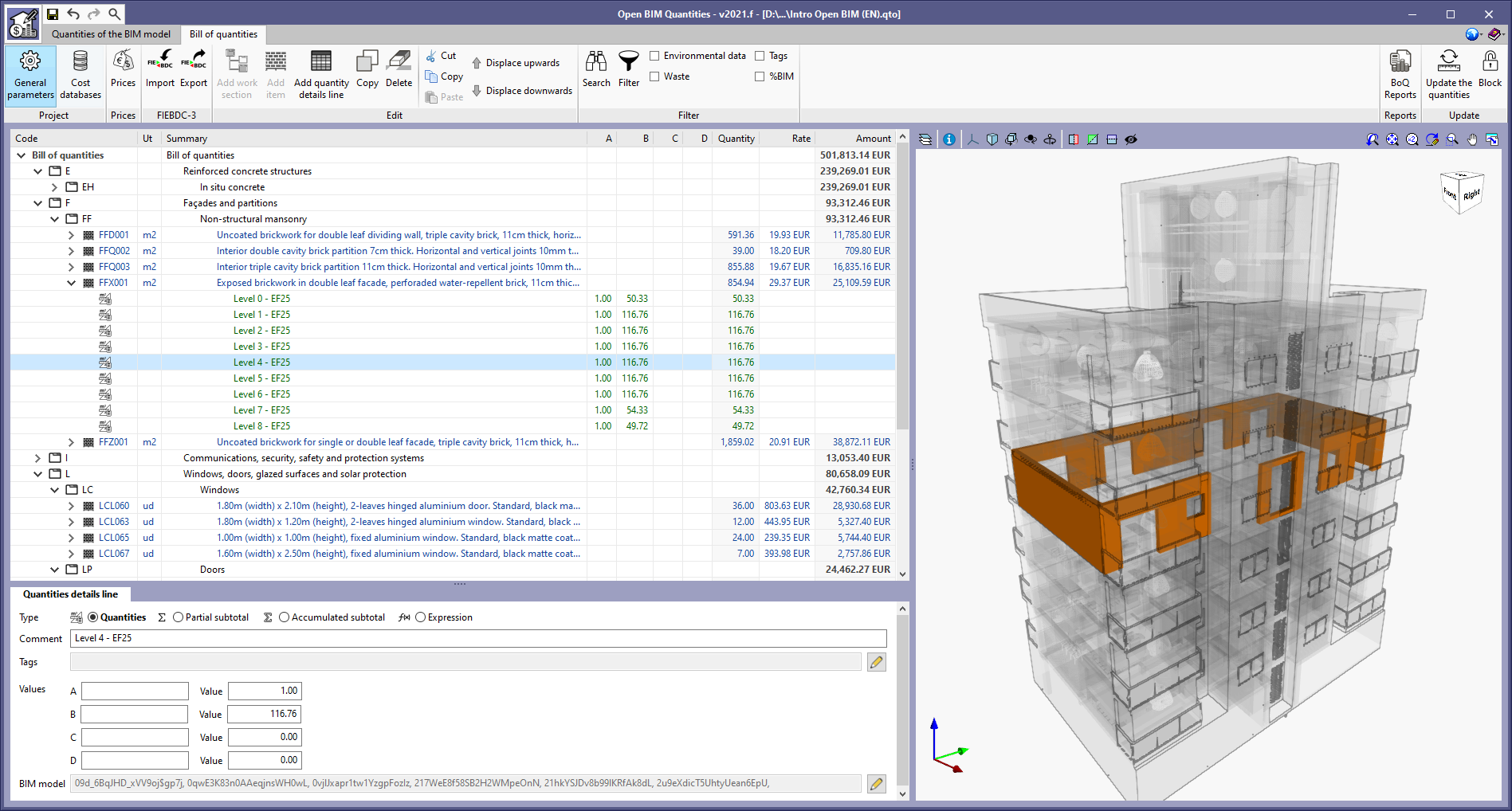
Item tags in measurement rules
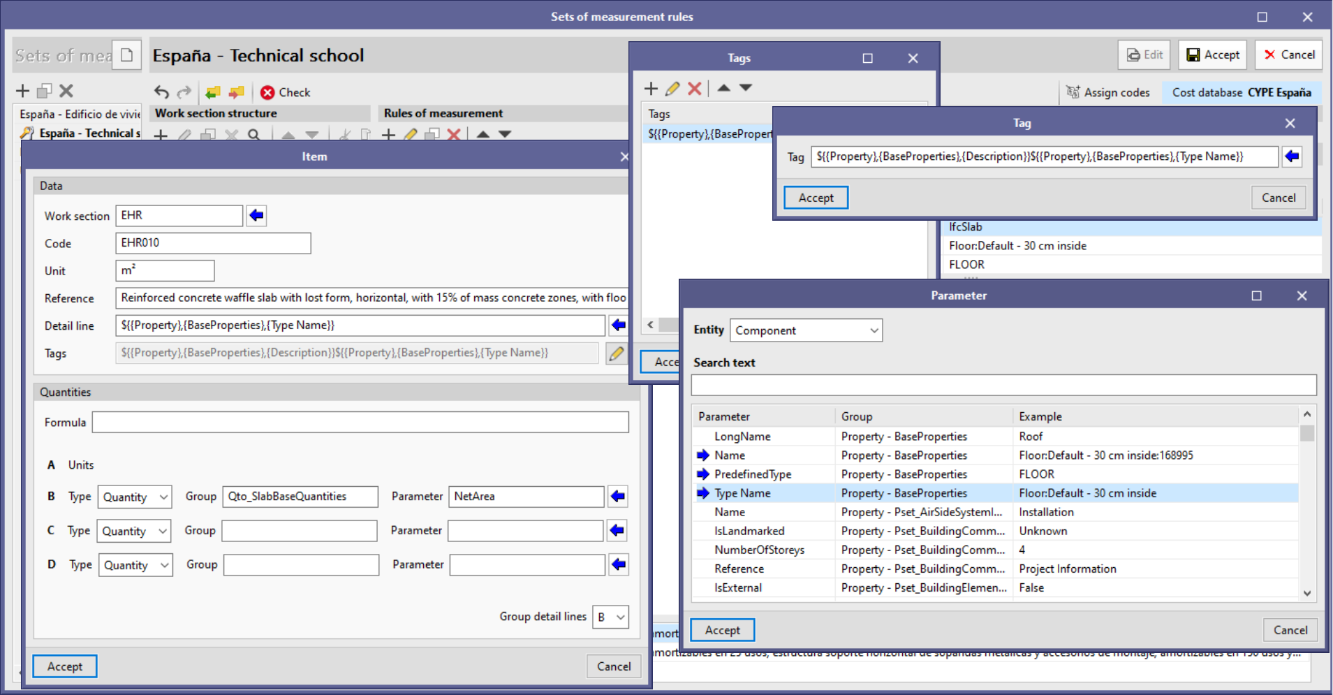
The "Tags" field has been added to the configuration of items generated through a rule of measurement contained within measurement criteria. Thus, it is now possible for users to associate the detail lines derived from the rule to a list of references that will allow them to be identified in the bill of quantities. In the "Bill of quantities" tab, it is possible to filter the detail lines according to their tags, along with the items and work sections that contain them. By using this filter, users can generate a partial bill of quantities for the project, e.g. according to the components' layout or construction phase.
When defining a text for a tag, variables from the properties and quantities of the BIM model’s IFC entities can be used in the same way as the composition of the detail line reference.
Spatial structure element properties
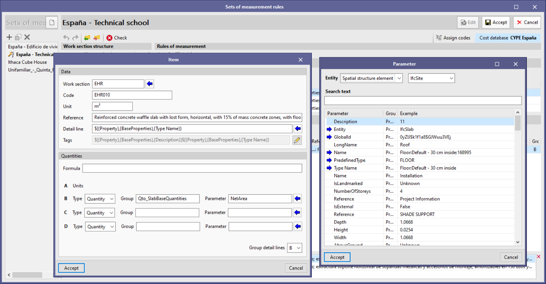
Thanks to the reading of the spatial structure elements of the BIM model in IFC format detailed in the new feature "View options of the BIM model", it is now possible to use their properties for improving the bill of quantity’s information. The possibility of introducing variables linked to the component's spatial structure element for defining the reference and tags of the detail lines has been implemented within the editing panel of the items generated by means of a rule of measurement.
The format for entering spatial structure element properties or quantities containing components of the selection defined in the rule of measurement is as follows:
${{.parent(Spatial structure element)}->${{Property/Quantity},{Set},{Parameter}}
For example, to obtain the name of the floor where the component is located:
${.parent(IfcBuildingStorey)}->${{Property},{BaseProperties},{Name}}
For easier input of these variables, spatial structure element selection has been added to the "Help" tool that is displayed upon clicking the blue arrow icon located next to the "Detail line" field or in the list of "Labels". Now, an "Entity" field appears with two options: "Component" and "Spatial structure element". If you select the latter, you must indicate which element you are referring to out of the possible options according to the IFC standard:
- Site ("IfcSite")
- Building ("IfcBuilding")
- Storey ("IfcBuildingStorey")
- Space ("IfcSpace")
Grouping of IFC entities by type
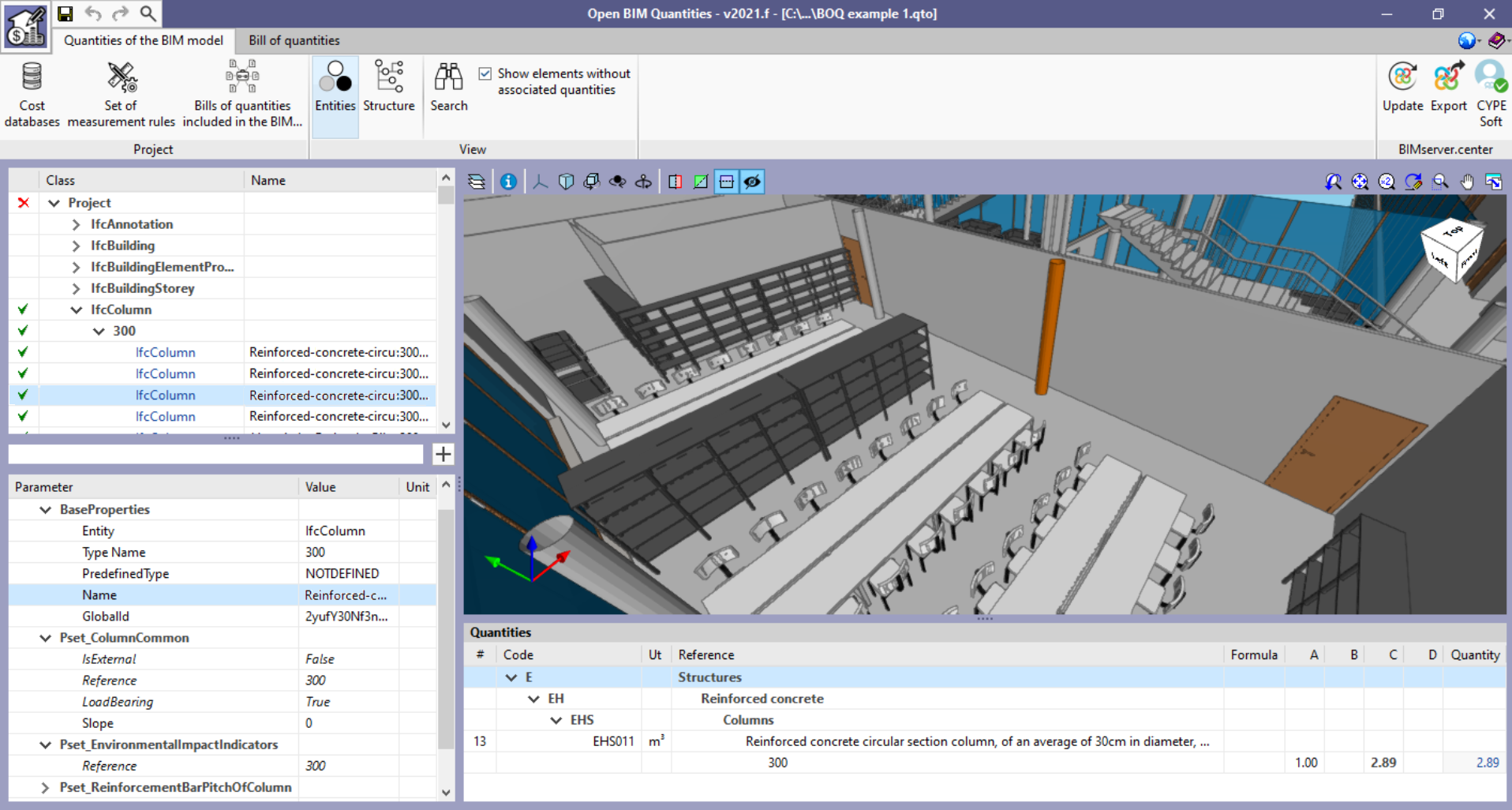
From version 2021.f onwards, BIM model components displayed in the cost breakdown structure of the "Quantities of the BIM model" tab are grouped according to their typology if one was associated to them. The typology of an element corresponds to the "Type Name" parameter of the "BaseProperties" property set.
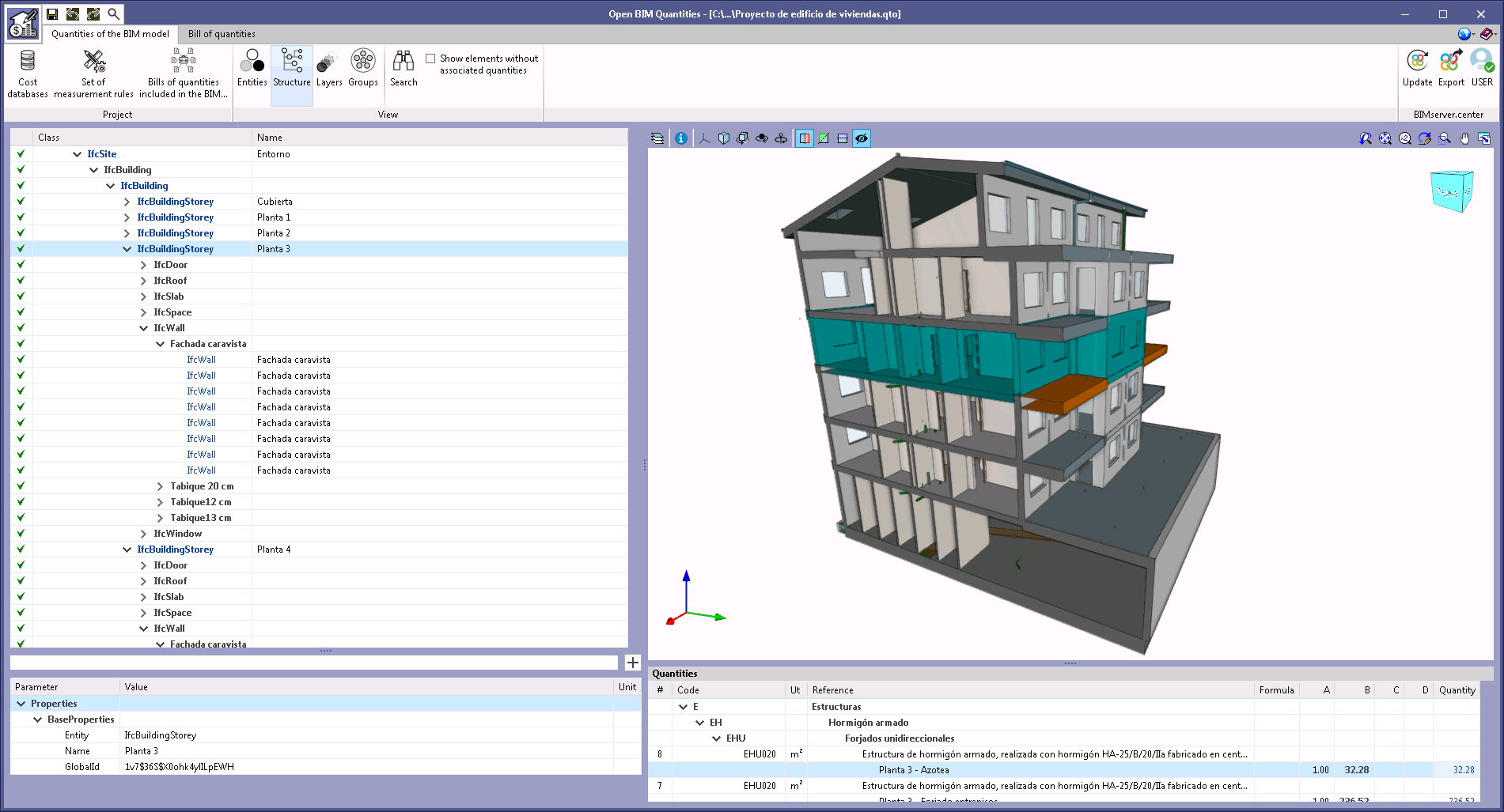
Marking BIM model components in 3D view
A change has been made to the way the model components in the "Quantities of the BIM model" tab are marked in the application's 3D view. In previous versions, only the elements selected by the user in the "Quantities" list were highlighted in orange. Now, the elements and groups that appear in the cost breakdown structure entity of the BIM model in IFC format are also highlighted in blue.
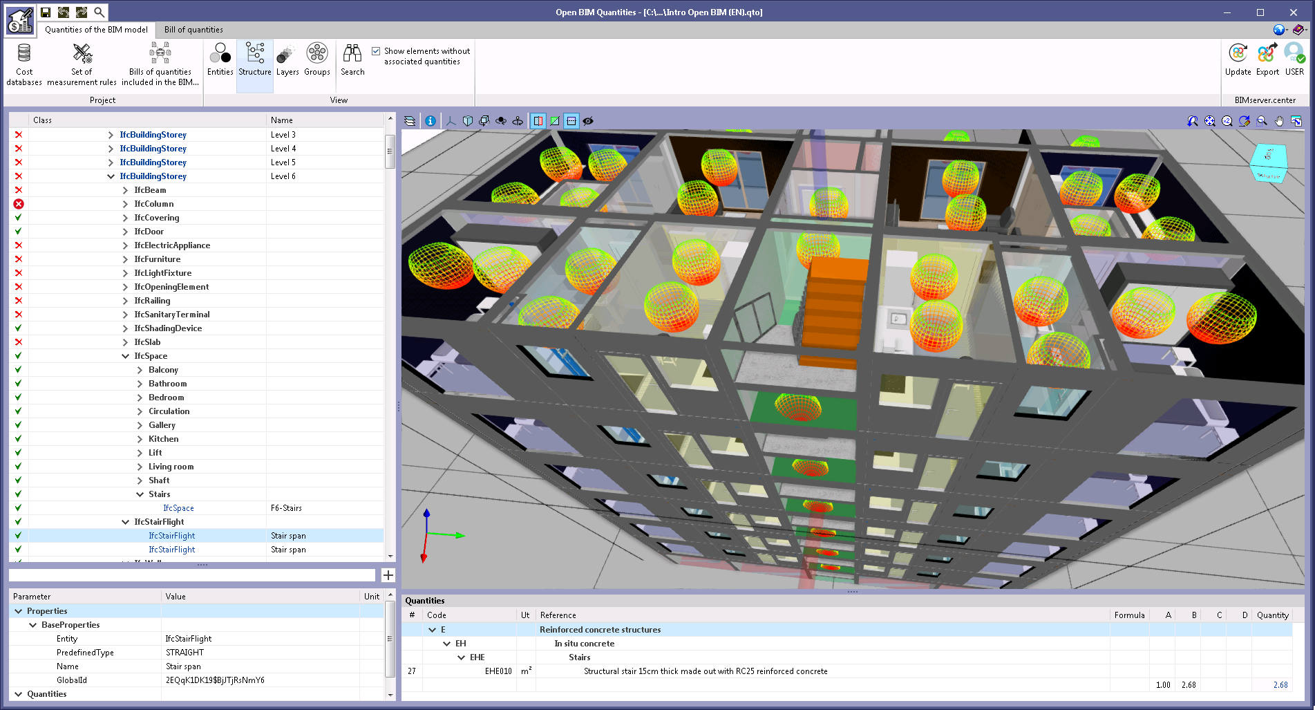
Text styles in the cost breakdown structure
Text styles have been added to the references of the BIM model cost breakdown structure elements, in the "Quantities of the BIM model" tab, to help identify them.
- Elements containing other elements are marked in bold. For example, spatial structure elements ("IfcSite", "IfcBuilding", "IfcBuildingStorey" and "IfcSpace") in the "Structure" view.
- Elements that correspond to the BIM model’s IFC entities are highlighted in blue. Black coloured elements are those created by the application for organising the components. E.g. groups for typologies and equal IFC entities.
Properties and quantities filter
A filter has been added for the properties and quantities of the BIM model components in the application's "Quantities of the BIM model" tab. When entering a text in this field, only those parameters containing this reference will be displayed in the list.
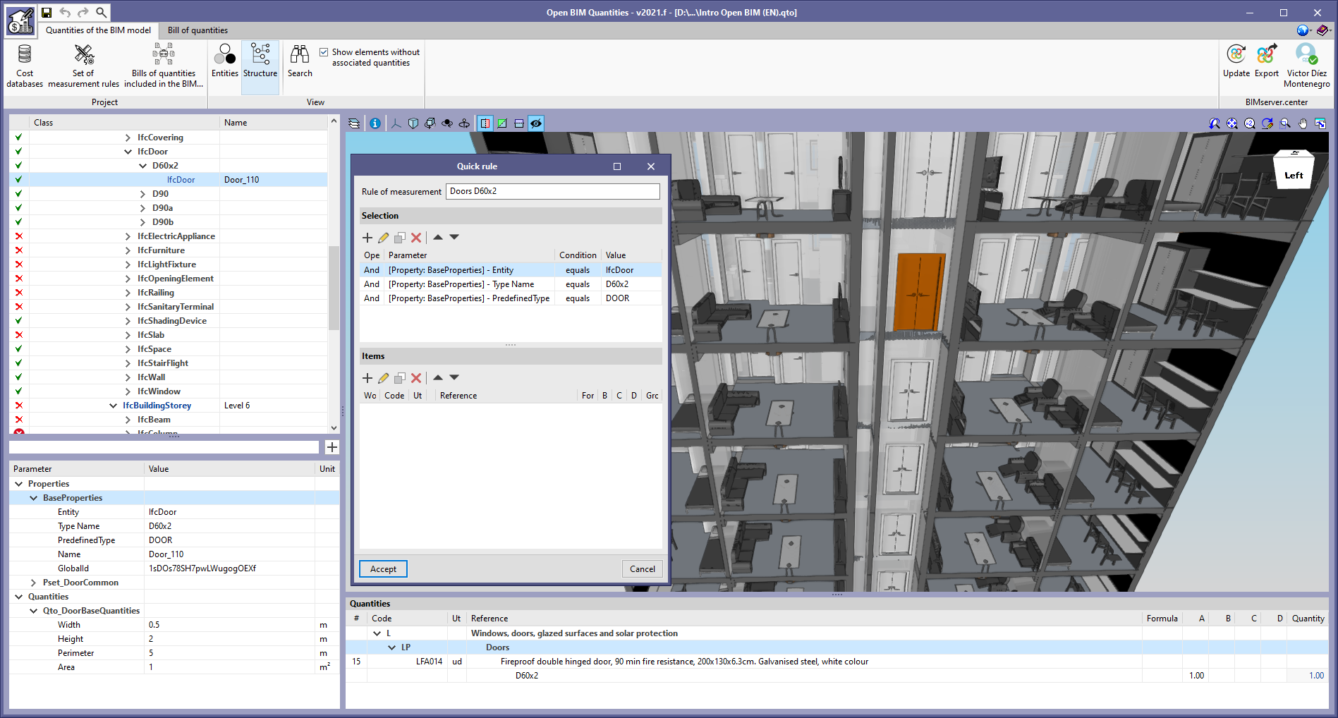
Quick measurement rules
A tool has been developed to add new rules to the active measurement criteria directly from the main window of the "Quantities of the BIM model" tab. To access this feature, a button has been added to the right-hand side of the text field for the "Properties and quantities filter". Pressing this button displays a window with the "Selection" and "Items" lists, as well as the rule of measurement reference. The "Selection" list starts with the property or quantity of the selected element. If the user selects a set of properties or quantities, all the properties or quantities within the set are added to the "Selection" list.
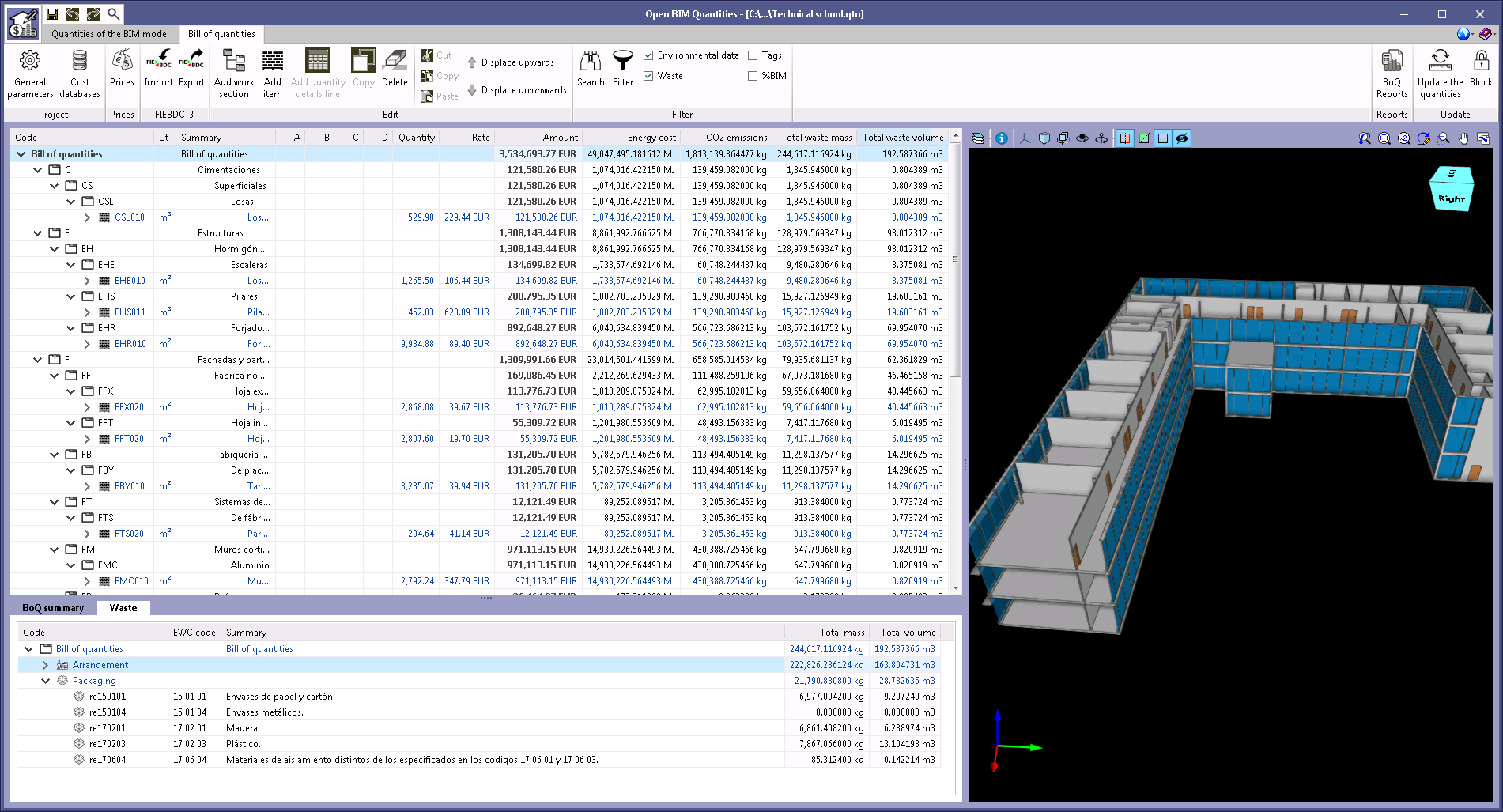
Update of example jobs
The example jobs "Proyecto de edificio de viviendas" and "Technical school" have been updated together with their associated cost databases and sets of measurement rules ("España - Edificio de viviendas" and "España - Technical school"). The purpose of this update is to consider the new features that have been carried out during the past versions, such as the new fields when exporting to FIEBDC-3 (.bc3) from the Price Generator or managing the properties of spatial structure elements.
Return to the 2021 version download area
Tel. USA (+1) 202 569 8902 // UK (+44) 20 3608 1448 // Spain (+34) 965 922 550 - Fax (+34) 965 124 950