
New features of existing programs
- New features common to several programs
- Open BIM aliaxis
- Open BIM MOVAIR
- Open BIM PANASONIC
- Code implementation and improvements in its application
- CYPE Architecture
- Open BIM Layout
- Open BIM Analytical Model
- CYPECAD
- StruBIM Steel
- CYPELEC Electrical Mechanisms
- CYPELEC Distribution
- CYPELEC PV Systems
- CYPEFIRE Design
- CYPEFIRE Hydraulic Systems
- CYPEHVAC Ductwork
- CYPETHERM LOADS, CYPETHERM Eplus, CYPETHERM HE Plus, CYPETHERM RT2012, CYPETHERM RT2012 CNOA, CYPETHERM COMETH, CYPETHERM RTExistant, CYPETHERM RECS and CYPETHERM Fujitsu
- Open BIM Quantities and applications with the Bill of Quantities tab
- Open BIM Quantities
- Applications with the Bill of Quantities tab
- Arquimedes
New features of existing programs
New features common to several programs
Section fills
This new feature is available in any CYPE program with a 3D interface. The section fills allow for the model to be viewed more clearly, this way avoiding some display problems that existed on plan and section views.
Open BIM aliaxis
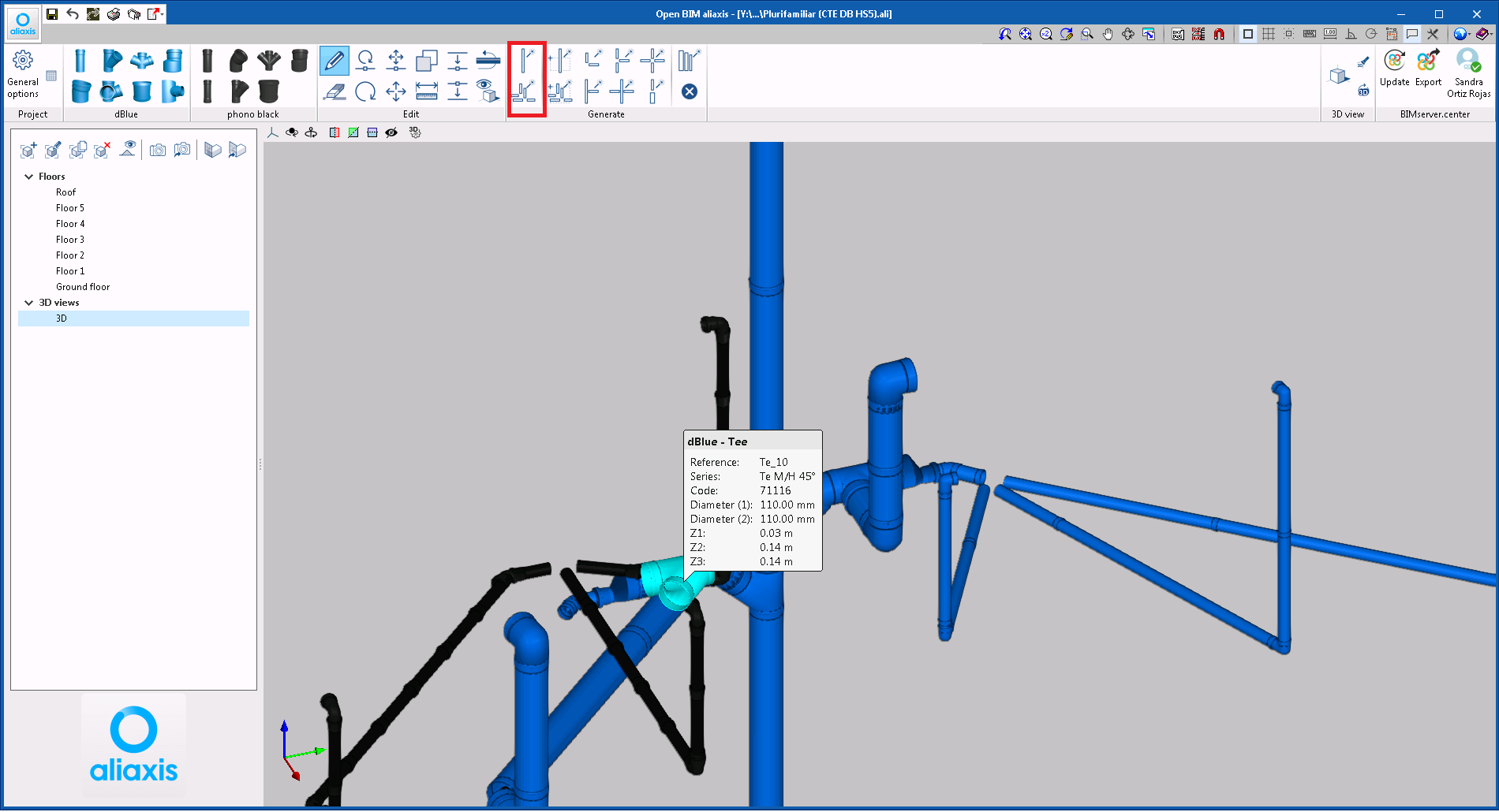
Automatic generation of pipes and accessories
Tools have been implemented that automatically generate all the pipes and accessories of the aliaxis catalogue for each part of the installation. To be able generate the elements, the BIM project of the BIMserver.center platform to which the Open BIM aliaxis is connected, must have information on the analysis of the installation. The BIM project obtains these analysis results from CYPEPLUMBING Sanitary Systems.
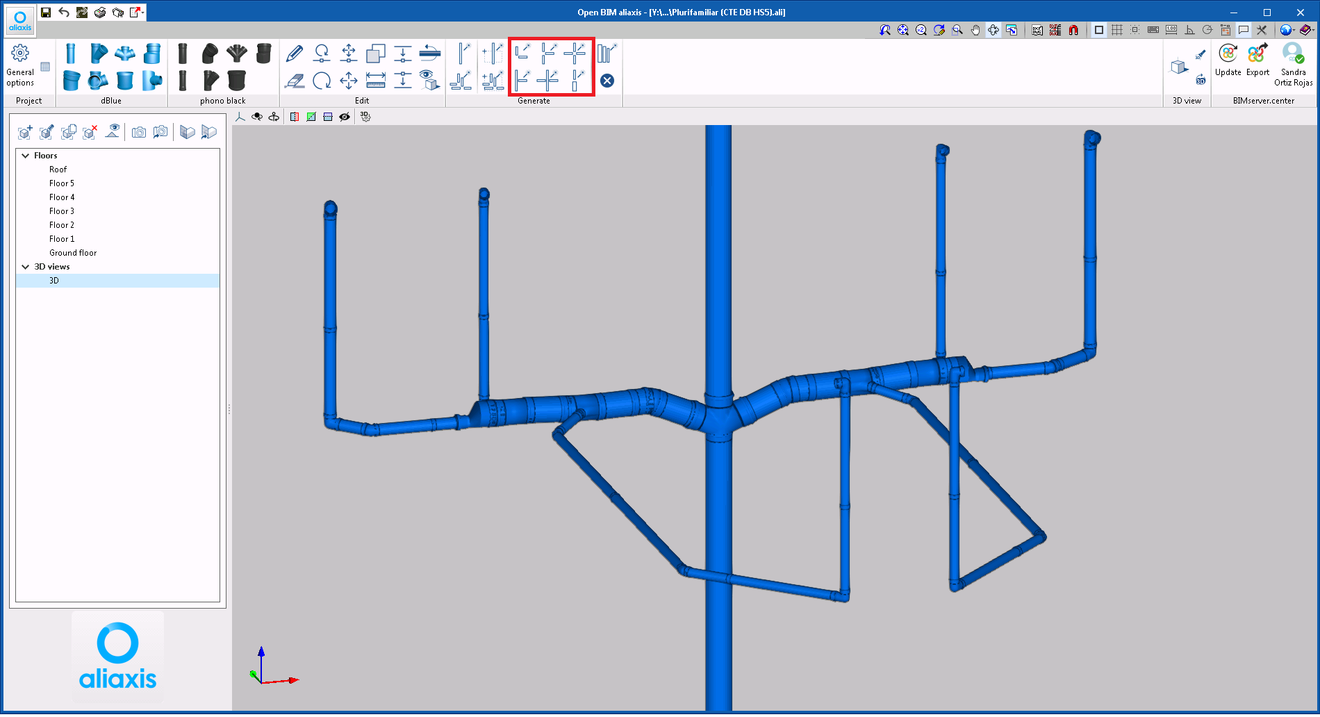
Tools have also been created to generate connections other than those that are generated automatically.
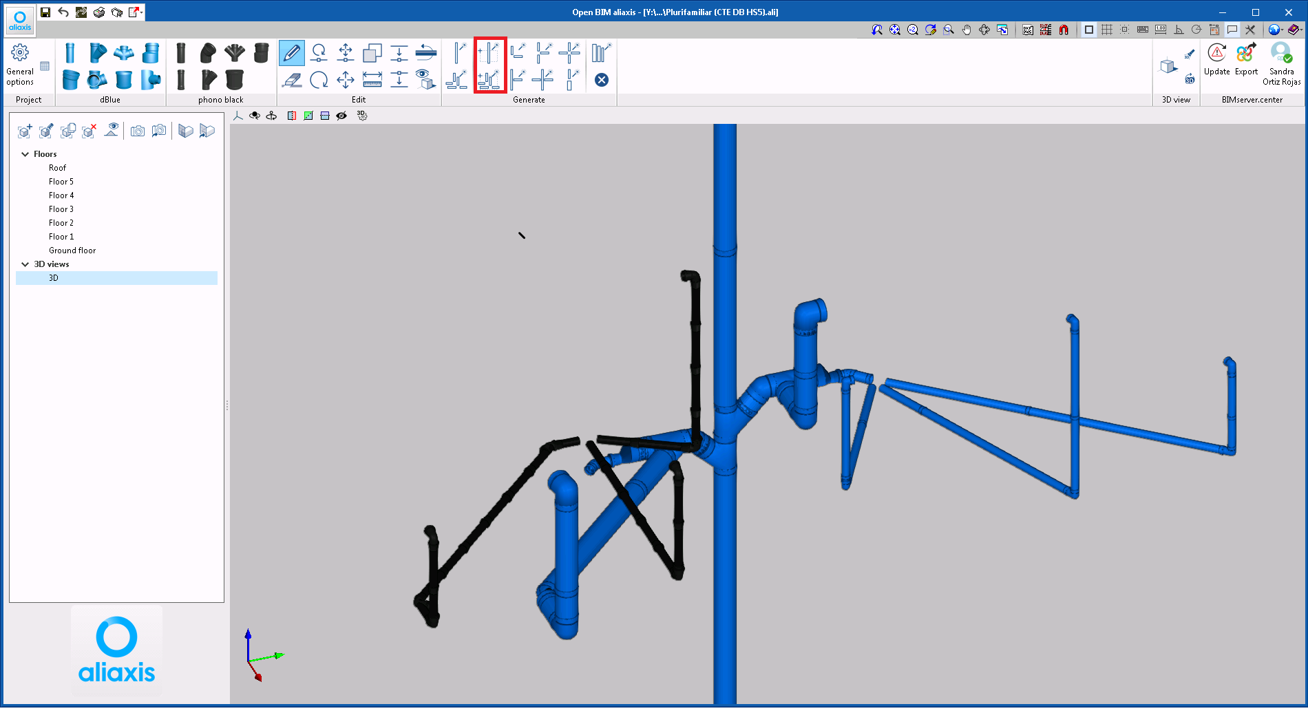
Furthermore, in this version (2021.c), it is possible to select parts of the installation so that different series of pipes and accessories can be assigned to them automatically.
Open BIM MOVAIR
Reading of design models included in the BIM project in IFC format
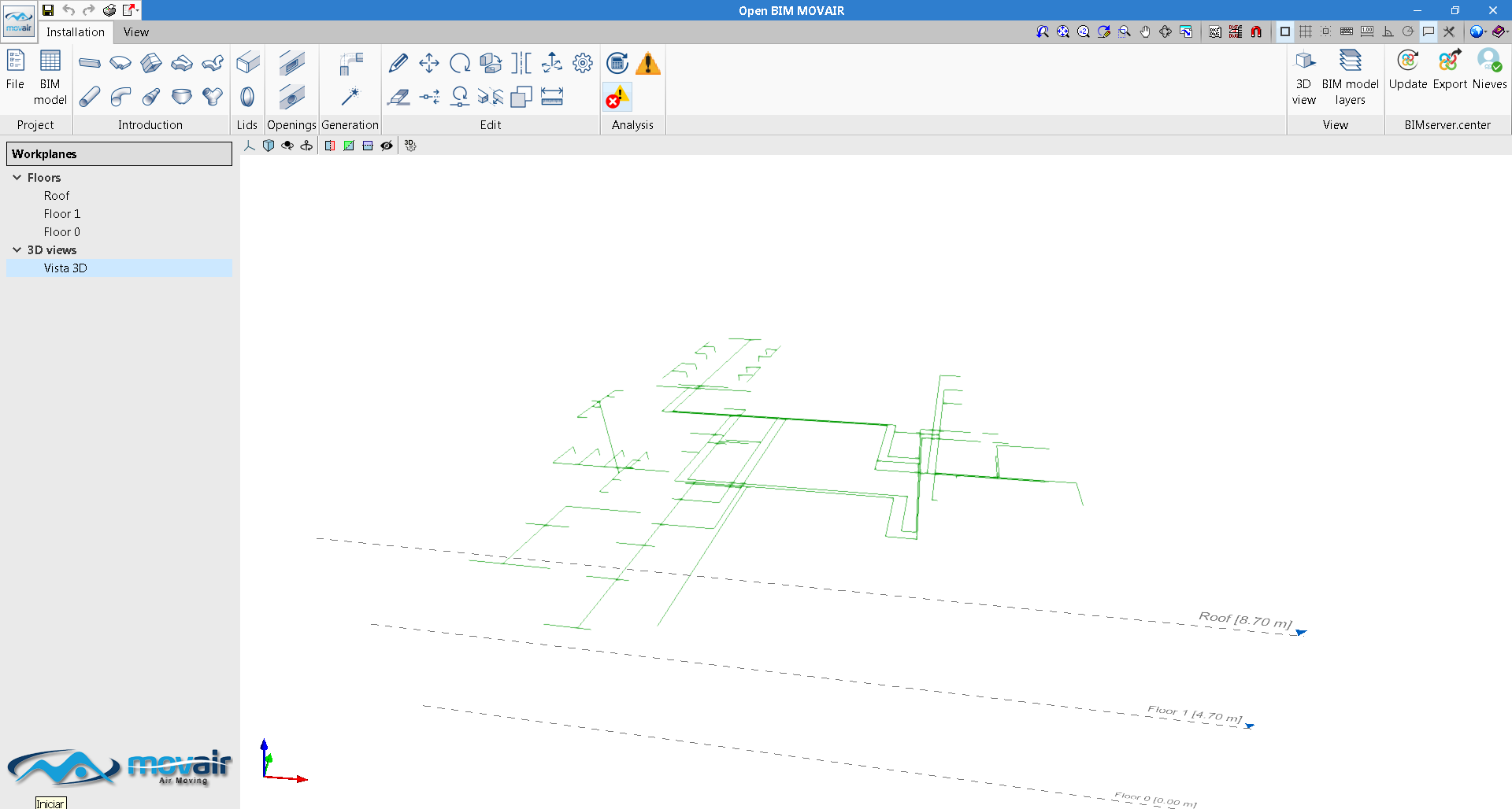
Since previous versions, Open BIM MOVAIR reads the information from the design model that has been generated by CYPEHVAC Ductwork from the BIM project that is located on the BIMserver.center platform. As of version 2021.c Open BIM MOVAIR also interprets the duct design models that are provided by other programs that include them on the BIMserver.center platform using the IFC standard format.
Now, by reading the design model (provided by CYPEHVAC Ductwork or by any other program that generates it in IFC format), Open BIM MOVAIR can represent the layout of the ducts on screen, using auxiliary lines, with all the information that is required to design the installation using parts from the MOVAIR catalogue.
Open BIM PANASONIC
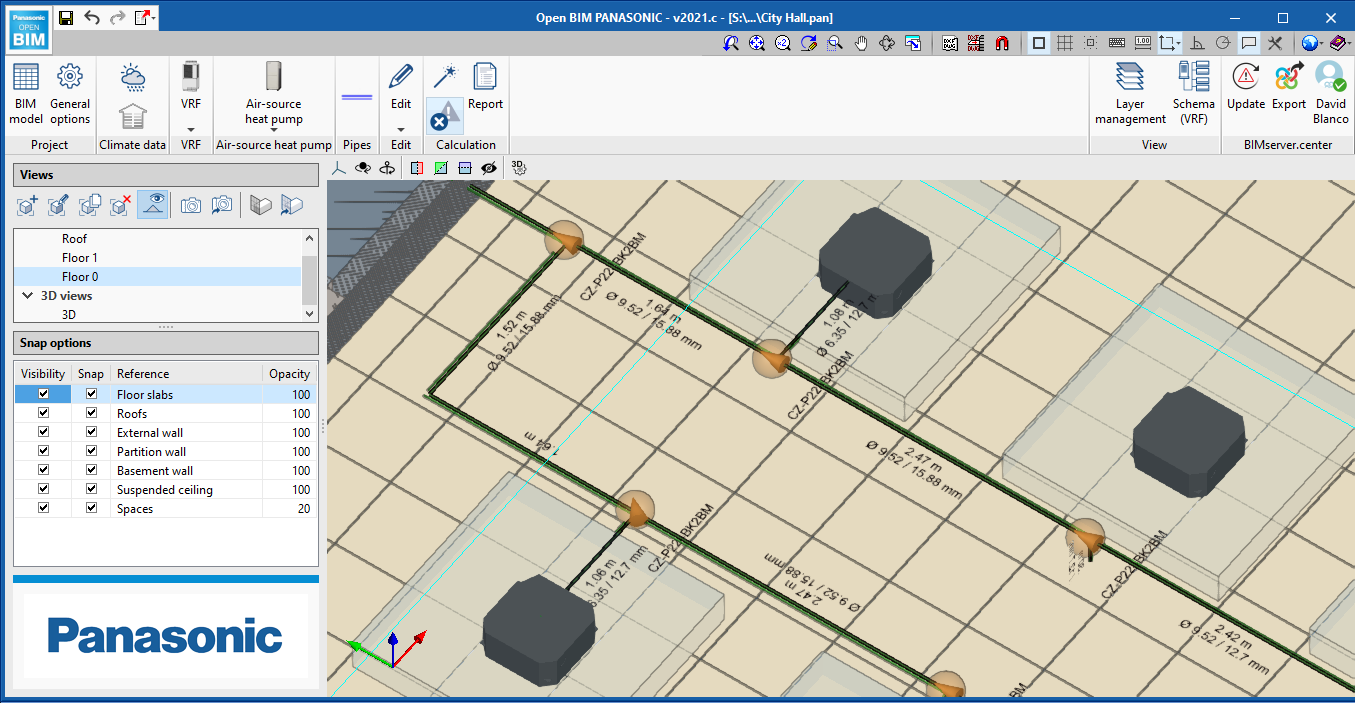
Visible information in the workspace
Now, the program displays the diameters and lengths of pipes, and the references of the equipment in the workspace.
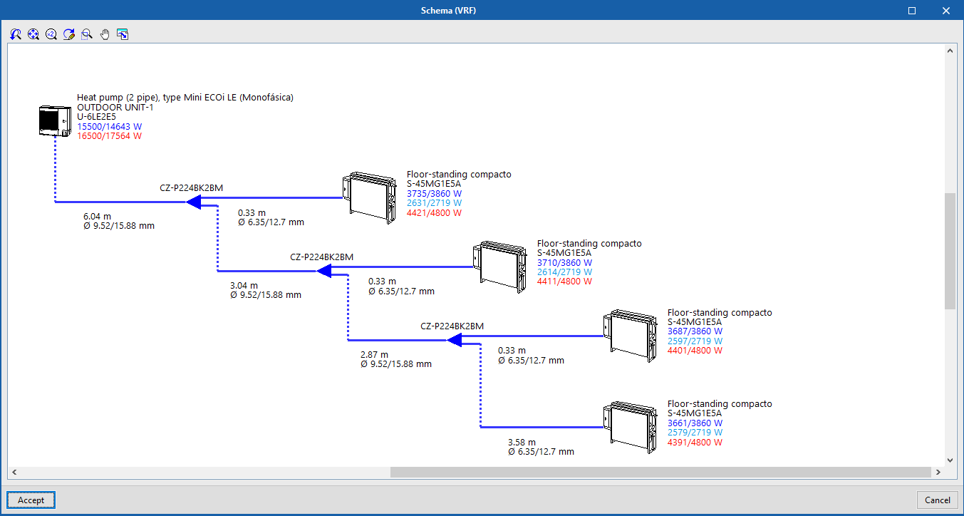
Furthermore, in the diagram that Open BIM PANASONIC generates automatically, the values for the total cooling, sensible and heating capacities are represented in blue and red respectively.
Code implementation and improvements in its application
Concrete structures
BRITISH STANDARD BS 8110-1:1997
Structural use of concrete. Part 1: Code of practice for design and construction.
Implemented in:
- CYPECAD
- CYPE 3D
- Shear walls
- Reinforced concrete cantilever walls
- Foundation elements
CYPE Architecture
Direct links to other applications
In this version of CYPE Architecture, you can find direct links to other applications that are available on BIMserver.center to continue to develop your project.
This way, you can add more information to your architectural model, such as: describe the construction solutions for each architectural element; check the urban regulations of your municipality; measure the model to obtain price estimates; arrange the electrical mechanisms for their subsequent design; or compose your project drawings.
- Construction solutions: After developing your architectural model, you can specify the construction solutions you want to use (type, composition by layers, materials, technical properties, etc.) This way, and using the Open BIM workflow, in addition to documenting your project, you will increase the quality of the information that is transmitted to the later phases of the workflow (thermal and acoustic analysis, bills of quantities, etc.). See more…
- Electrical mechanisms: You can arrange the electrical mechanisms (switches, socket outlets, connectors, etc.) of your project on the architectural model. Remember that this layout is normally subject to applicable regulations in the scope of your project (minimum requirements, exempt spaces in damp rooms, etc.). The "CYPELEC Electrical Mechanisms" application will assist you with this task and help you to comply with the applicable regulations. See more…
- Urban planning: If you have already completed your building model, you can review and check the urban planning regulations of the municipality where it is located (buildability, occupancy, habitability, setbacks, maximum heights, etc.) in an intuitive way on your 3D model. Check beforehand that your model complies with the urban planning regulations of your municipality using the "CYPEURBAN" program. See more…
- Bills of quantities: It is possible to generate the bill of quantities of the architectural model using the information contained in the IFC model that is generated and exported by "CYPE Architecture". Using different measurement rules and a cost database, "Open BIM Quantities" allows users to transform the properties and quantities that are associated with the architectural elements into job units that make up the budget. See more…
- Drawing composition: The composition of architectural drawings (views, sections, floors, elevations, etc.) is created using the 3D model that is generated by "CYPE Architecture". The "Open BIM Layout" application provides users with the necessary tools to produce the project drawings, and allows for the 3D models from other disciplines (plumbing, electricity, structure, telecommunications, waste water management, etc.) to be represented simultaneously. See more…
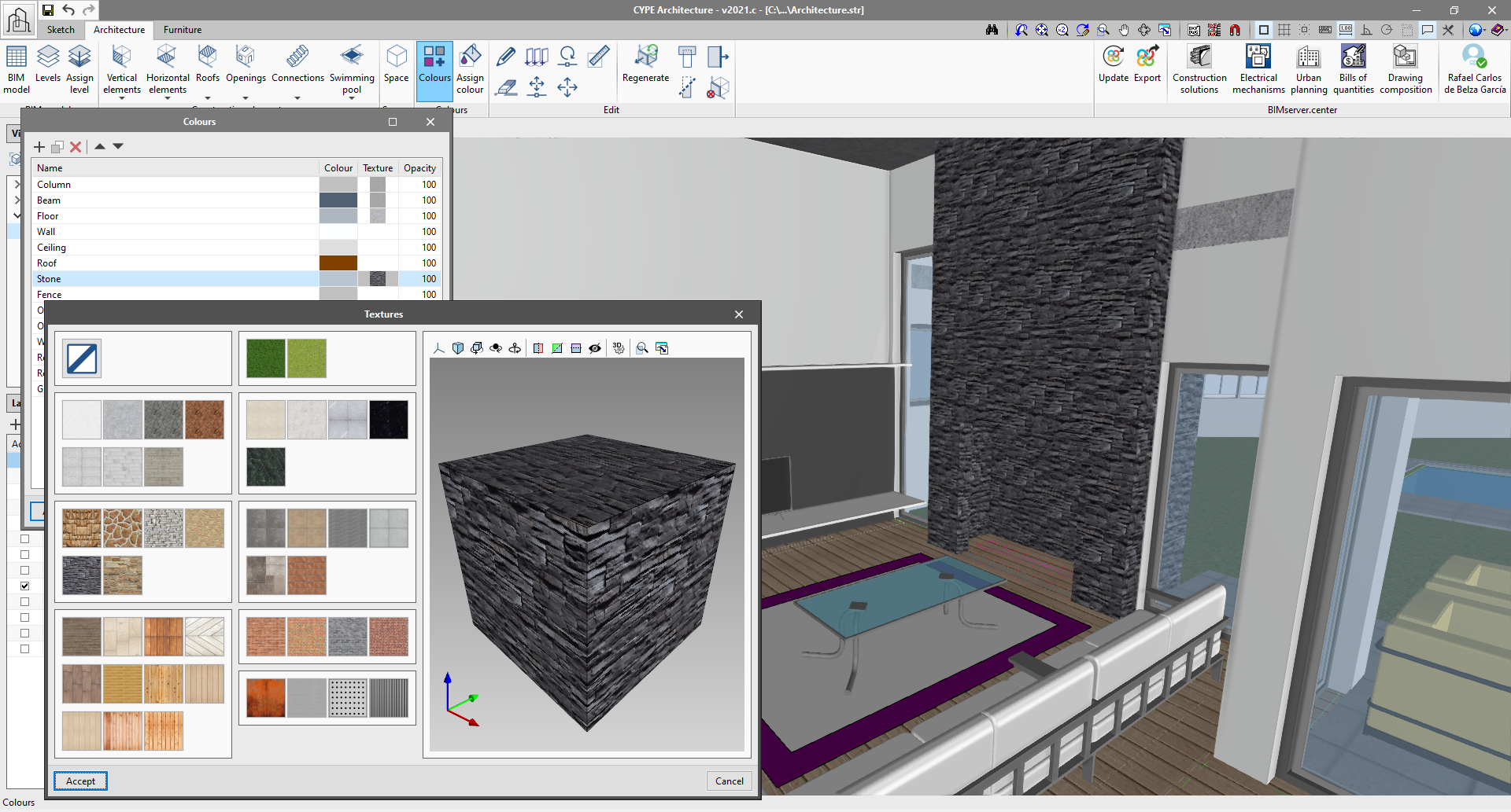
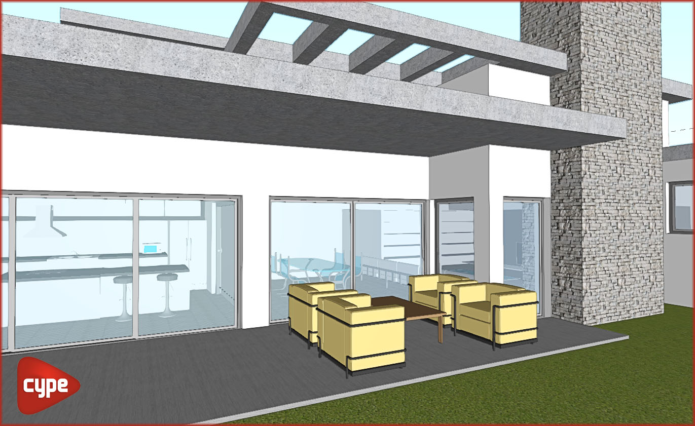
Add textures to our building model
Since the previous version (2021.b), CYPE Architecture has an option with which users can edit the colour of the elements of the "Architecture" tab using the "Colours" button.
Taking advantage of this tool, in the 2021.c version, the "colours" panel also allows users to assign a texture to each colour of the library, and so, give the model a more realistic appearance.
The library contains 43 textures that are classified by groups (timber, concrete, stoneware, marble, steel, stone, brick and grass).
From the layers panel, users can show or hide textures during the modelling process.
The textured model can be viewed both on the BIMserver.center platform and in the rest of the Open BIM workflow programs.
Section fills
This new feature is available in CYPE Architecture and in any program with a 3D CYPE interface. The section filling allows the model to be viewed more clearly, thus avoiding some display problems that existed in plan and in section.
To view the fill correctly in the other BIMserver.center applications, you must re-export the project from "CYPE Architecture".
Other improvements and corrections
Improvements and corrections have been made to the following functionalities: walls, curtain walls, columns, floors, windows, doors, openings, spaces, tiles, roof ridges and valleys, and furniture.
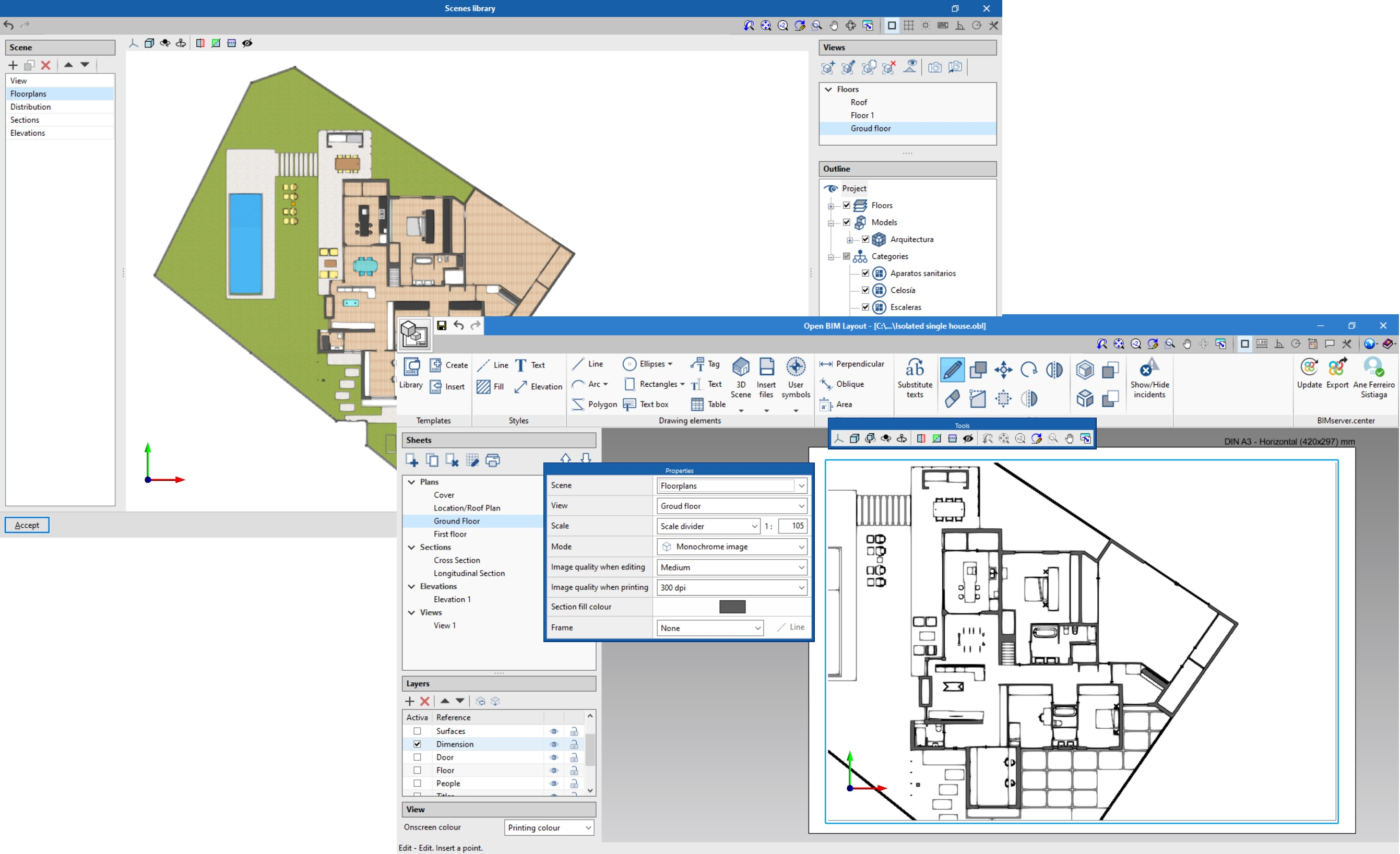
Open BIM Layout
Program remodelling
The 2021.c version of Open BIM Layout has been remodelled and includes new features and ways of working to give greater potential to the program when generating drawings using a BIM model.
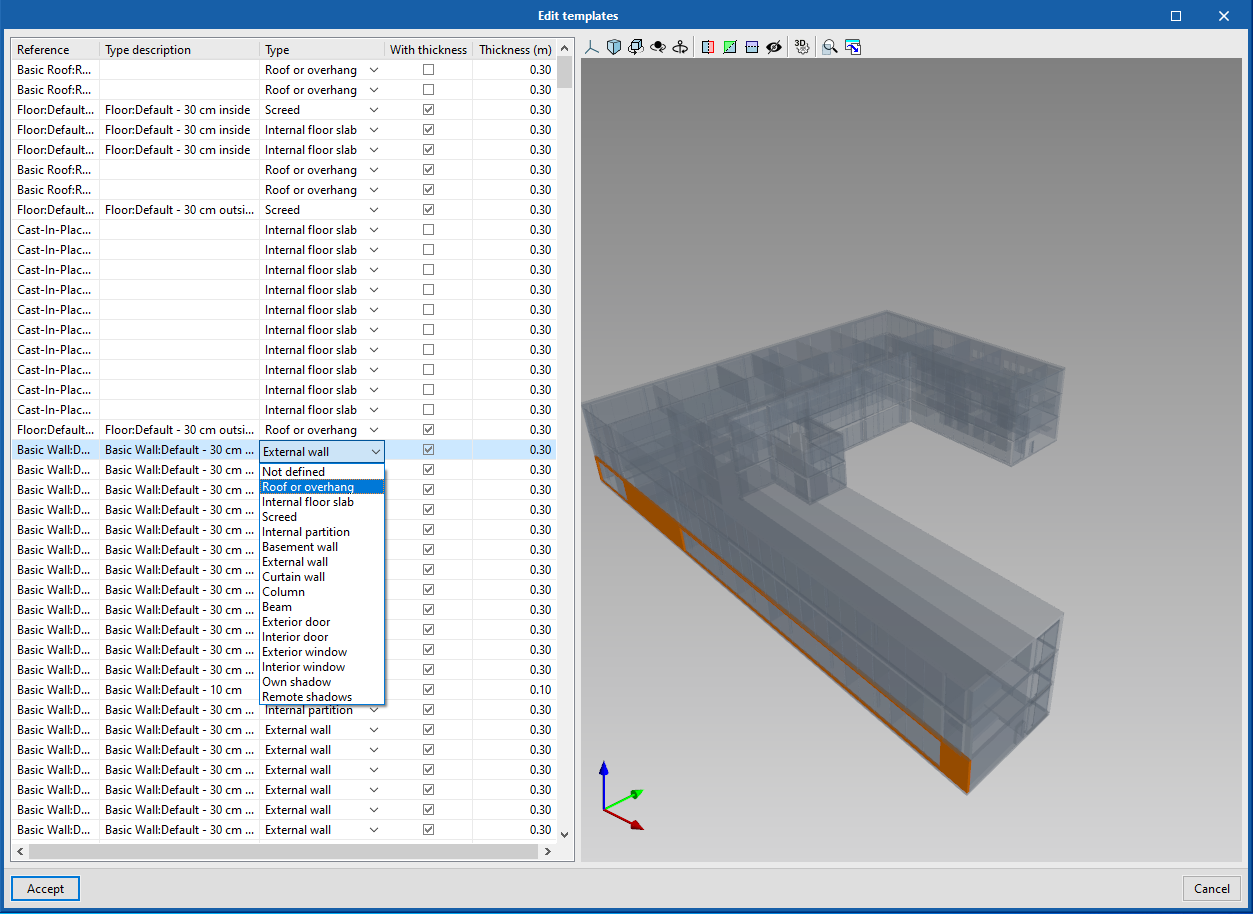
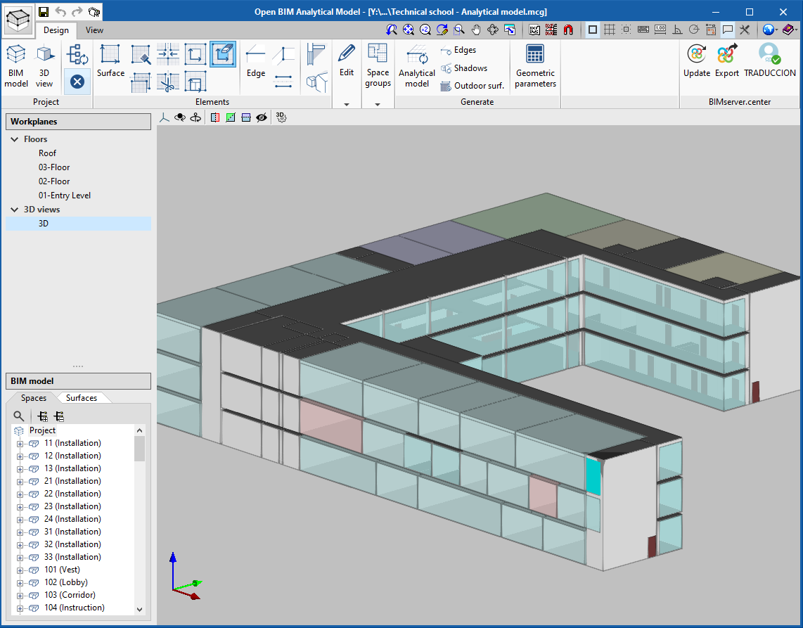
Open BIM Analytical Model
Assign shading elements to the components of the physical model
As of the 2021.c version, using the "Edit template" tool, users can modify the typology of a component of the physical model in order to indicate whether it acts as "Own shadow" or "Remote shadow". This is especially important when executing the automatic generation process of the analytical model since it needs to know which elements produce shading in order to include their derived surfaces in the shading group.
"Delete opening" tool
The option "Delete opening" has been added within the "Elements" group of the application toolbar. Thanks to this new tool, it is now possible, to eliminate openings that are associated with surfaces of the analytical model, graphically on the work area. In previous versions, the only alternative was to delete the openings by manually editing the BIM model of the project (Project> BIM Model).
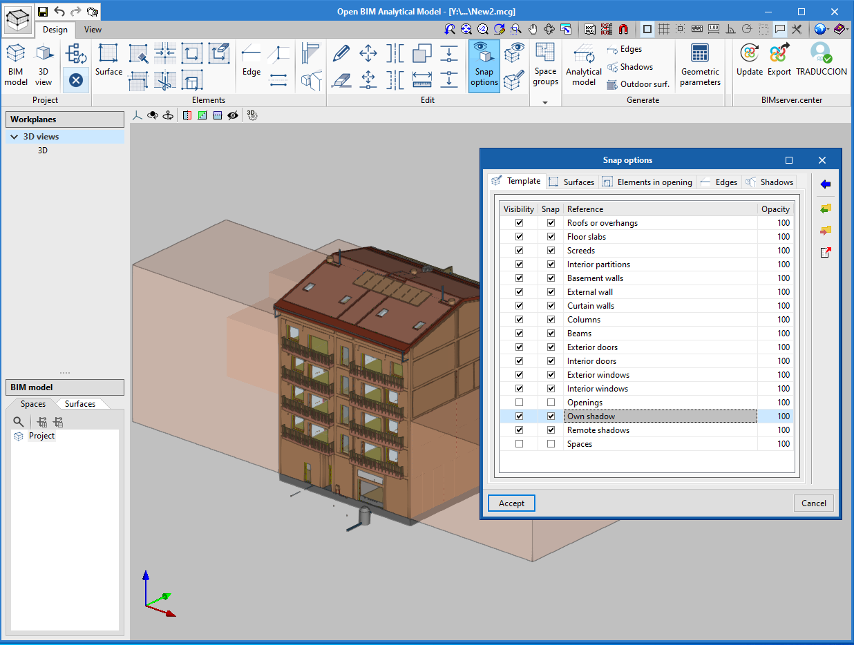
View the shading elements of the physical model
The element groups "Own shadows" and "Remote shadows" of the physical model have been added to the object snap options of the application. This way, it is now possible to view and snap to them in order to define their derived surfaces in the analytical model of the building.
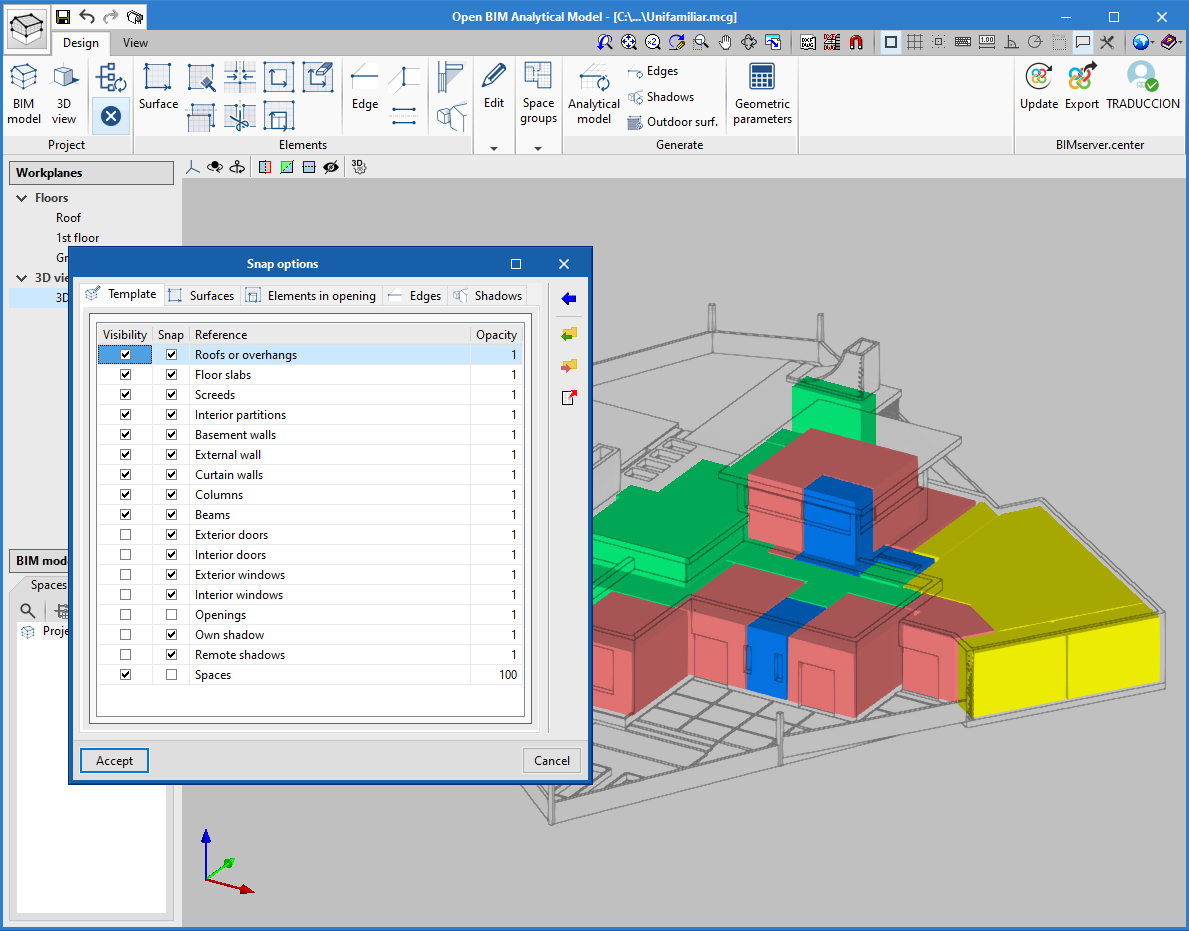
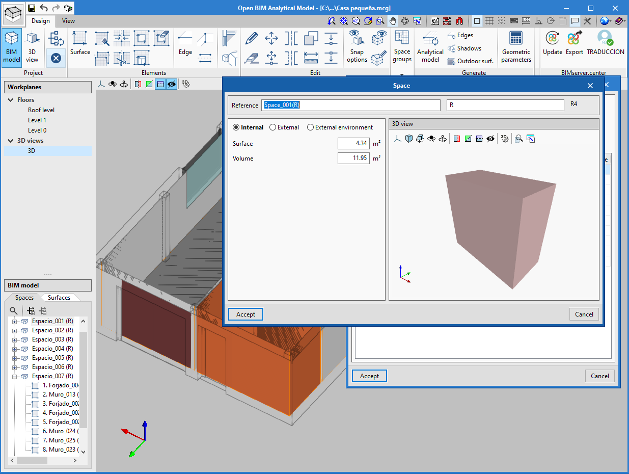
View the spaces of the physical model
The "Spaces" of the physical model have been added to the object snap options of the application. This way, it is now possible to view and snap to the 3D outlines of architectural spaces in order to define their surfaces and derived edges in the analytical model of the building. It should be noted that the surfaces that make up the outline are used by the automatic generation process of the analytical model. Consequently, thanks to this implementation, users can verify that they are defined correctly before executing the task.
Improved accuracy of the algorithm for the automatic generation of the analytical model
The algorithm that automatically determines the analytical model of the building from the architectural model has been improved. Amongst the adjustments that have been carried out, the level of precision in the detection of surfaces in small rooms has been increased and the analysis of shading elements with complex geometries has been improved.
This optimisation represents an increase in the quality of the information that CYPE's Open BIM applications for thermal and acoustic analysis can read.
CYPECAD
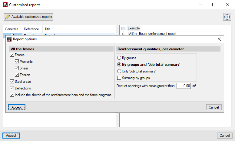
Customised reports. New predefined reports
In the previous version (2021.b) the possibility to customise reports in CYPECAD based on predefined reports was implemented.
Now, in the 2021.c version, the following predefined reports have been added to optionally include them as chapters in the customisable reports:
- Beam reinforcement report
- Beam takeoff
- Job takeoffs
- Reinforcement quantities, per diameter
If any of these chapters is selected, it is possible to configure the data to be listed using the "Report options" button.
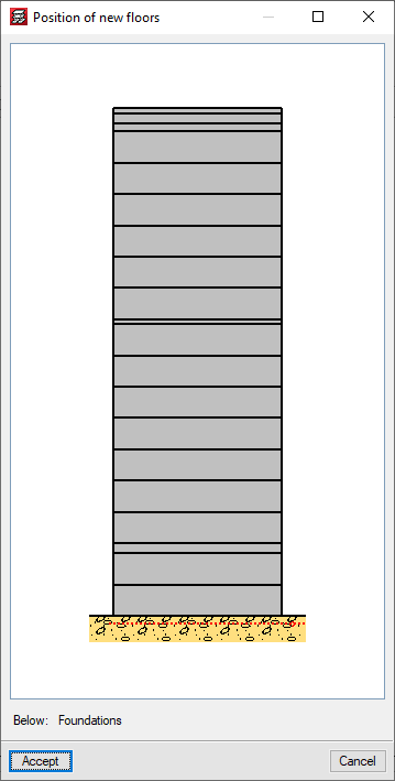
Add a group below the current foundation group
As of the 2021.c version, the "New floors" option allows for floors to be added below the current foundation group.
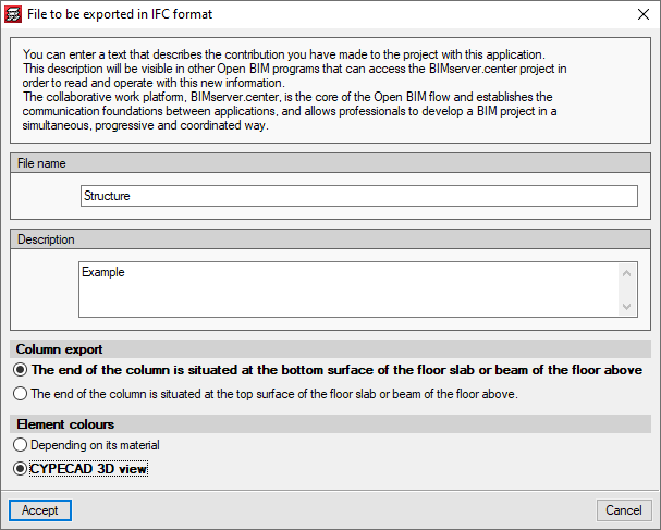
Exported element colours
Users can choose the colours with which the elements of the project are exported in two different ways:
- According to its material
Elements of different types but with the same material are shown with the same colour. For example, a concrete column and a concrete beam have the same colour. - 3D view of CYPECAD
Each item will have the same colour as in the 3D view.
Other improvements and corrections
The 2021.c version of CYPECAD also includes other small improvements and correction of issues that could occur in unique cases:
- When a beam is inserted or extended, it is possible to snap to any point at the end of a wall. Until the 2021.c version, it was only possible to snap to the axis of the wall.
- It is possible to copy the elements that have been entered, from one group to another, using editing resources with the "Copy elements to another group" option.
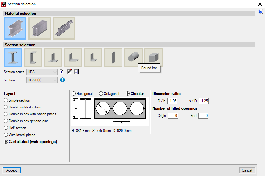
- When a castellated beam is defined, the depth and other dimensions of the section are displayed. The depth is also shown in "Beams - Information".
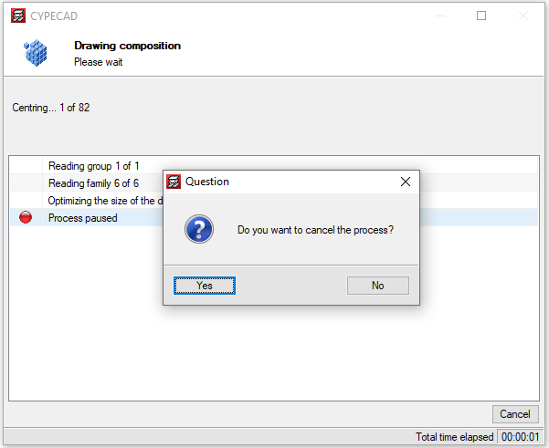
- By pressing the "Drawings" button, information is generated for all the possible drawings. This is generally quite fast except in some "Column schedule" and "Column details" drawings. As of the 2021.c version, it is possible to cancel the process to obtain this information if the corresponding drawings are not going to be generated.
- The "Centre of mass and centre of stiffness" selection of "Visible references" remains after the program is closed.
- Upon changing the initial or final group of a column, users can edit the fixity and buckling coefficients at the new floors.
- A new check for panel outline intersections is included. This check is done before the project is analysed to avoid later errors.
This situation has been found to occur in some cases when beams with very different widths meet. - The forces at column starts which are shown in the "Column starts, shear walls and walls by loadcase" chapter take into account the elements that are connected to the start, in the same way as those shown in the "Foundation loads" drawing.
- During the update process of the BIM model, the templates of the columns are updated.
- The export process of the deformed shape to the BIM model has been improved, whereby its incorrect positioning in certain occasions, has been corrected.
- The detection of concrete columns during the import of IFC files has been improved. Previously, in certain cases, no columns were detected.
- An error that occurred when selecting "Strap and tie beams > Match" in a project that had not been analysed has been solved.
- An error has been solved that caused that, after editing column starts, the length of the starts was not shown in the "Column schedule" drawing in certain circumstances.
- An error that occurred in some cases when "Import series of drawings" was selected in a project that had not been analysed has been solved.
- A wall data inconsistency error has been solved, which could occur when a floor was added over another in which walls had previously been inserted on other walls.
- An error that occurred when consulting forces for combinations in timber or composite columns has been solved.
StruBIM Steel
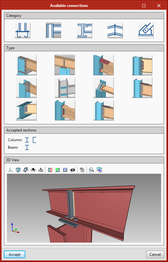
New connection selection dialogue box
The connection selection dialogue box has been improved, where the available connections have been grouped into various categories. The different types of connections are now shown with an image.
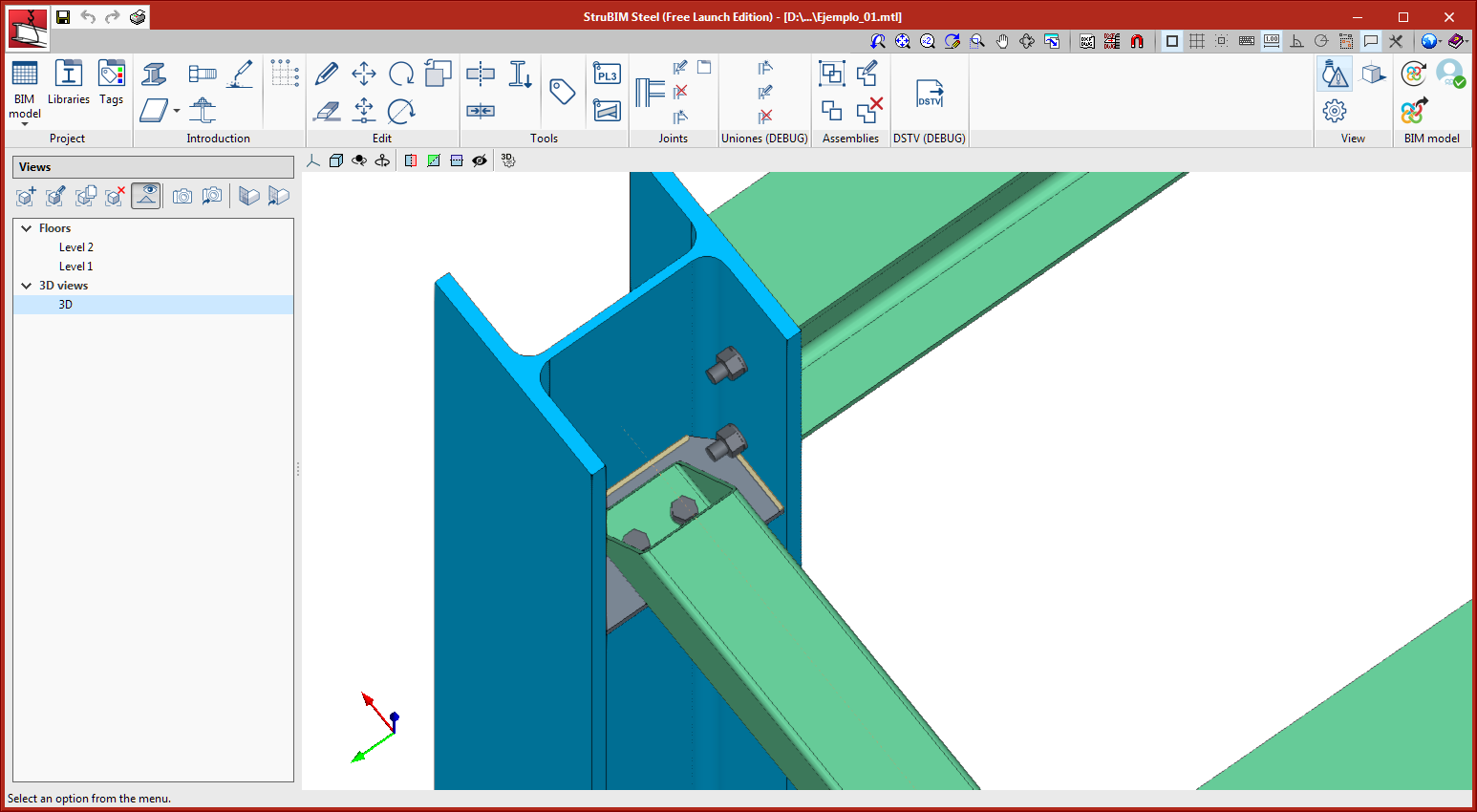
New types of connections
The following types of connections have been implemented:
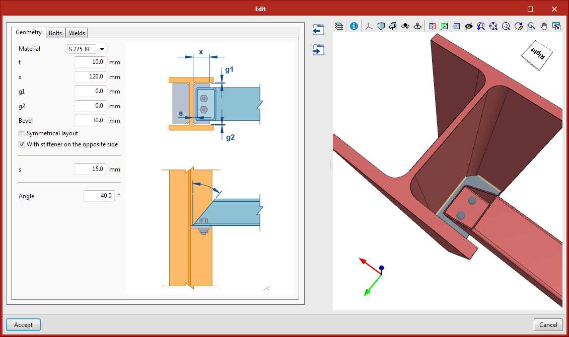
Rectangular tube to stiffener connection
Bolted connection between a rectangular tube and the I-section web stiffener. A cutting angle at the end of the tube is defined to be able to place the bolts inside the tube.
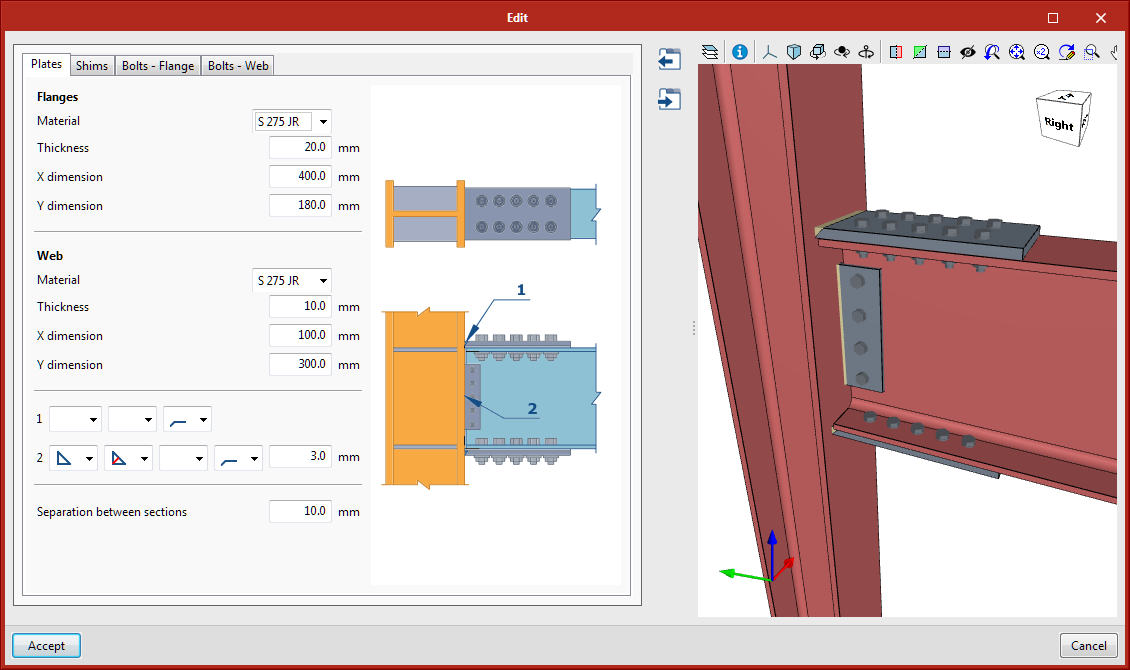
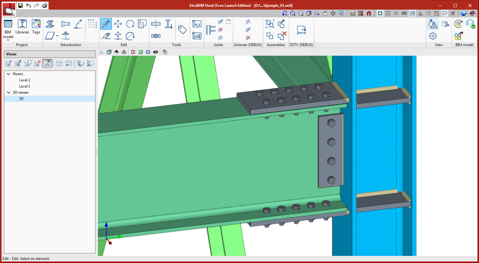
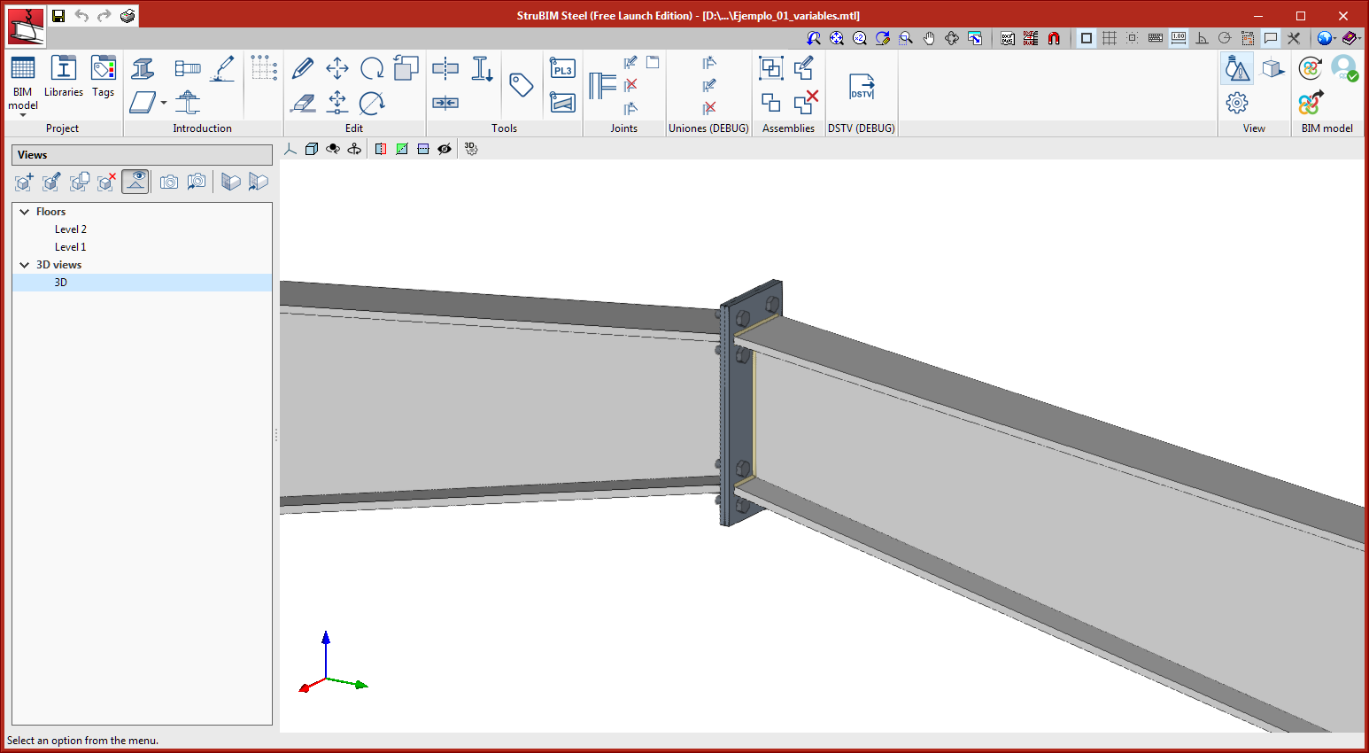
Column to beam moment connection with plates bolted to the web and flanges
This connection joins I-section columns and beams. It is a moment connection in which the flanges and web of the beam are bolted to plates that are welded to the column. The plates of the flanges are joined to the column using butt welds. The web plate can be connected to the column with fillet or butt welds.
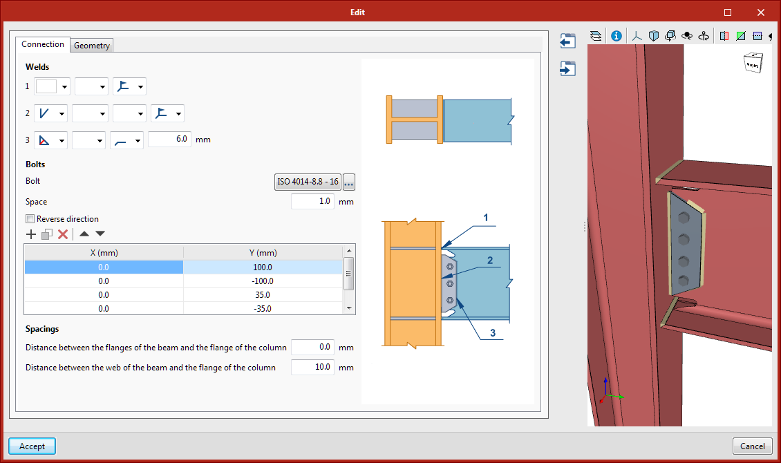
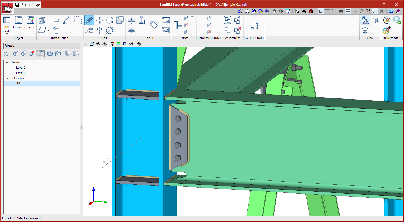
Column to beam moment connection with bolted side plate and welded to the beam
This connection joins I-section columns and beams. It is a moment connection in which the flanges of the beam are joined to the flange of the column using butt welds. The web of the beam is connected to the column using a side plate that is welded and bolted to the web of the beam.
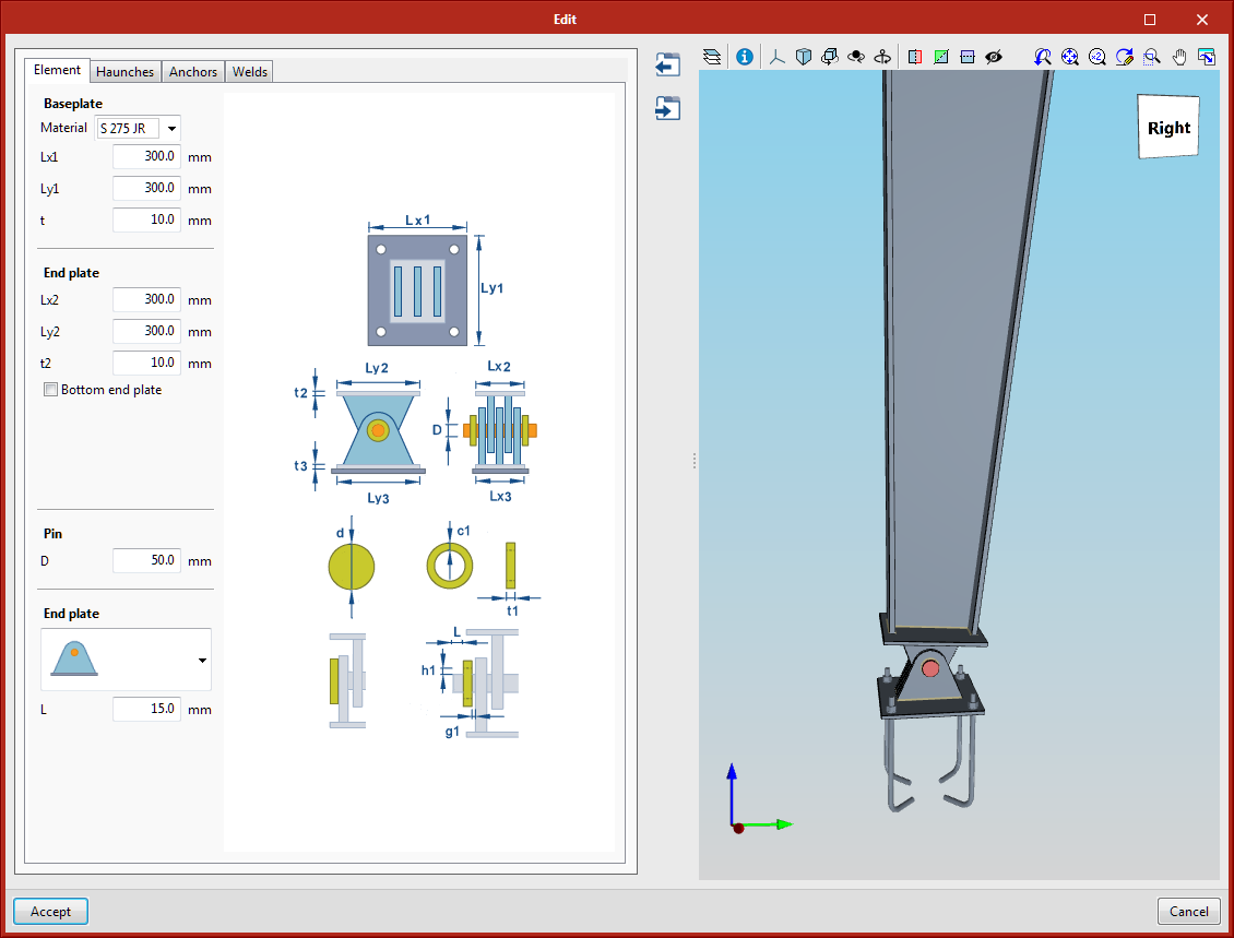
Connection adaptations of reinforced variable depth sections
Various connections have been adapted to reinforced sections with variable depth. The adapted connections are:
- 001 - Pin connection
- 002 - Anchorage plate
- 006 – Splice connection using an end plate
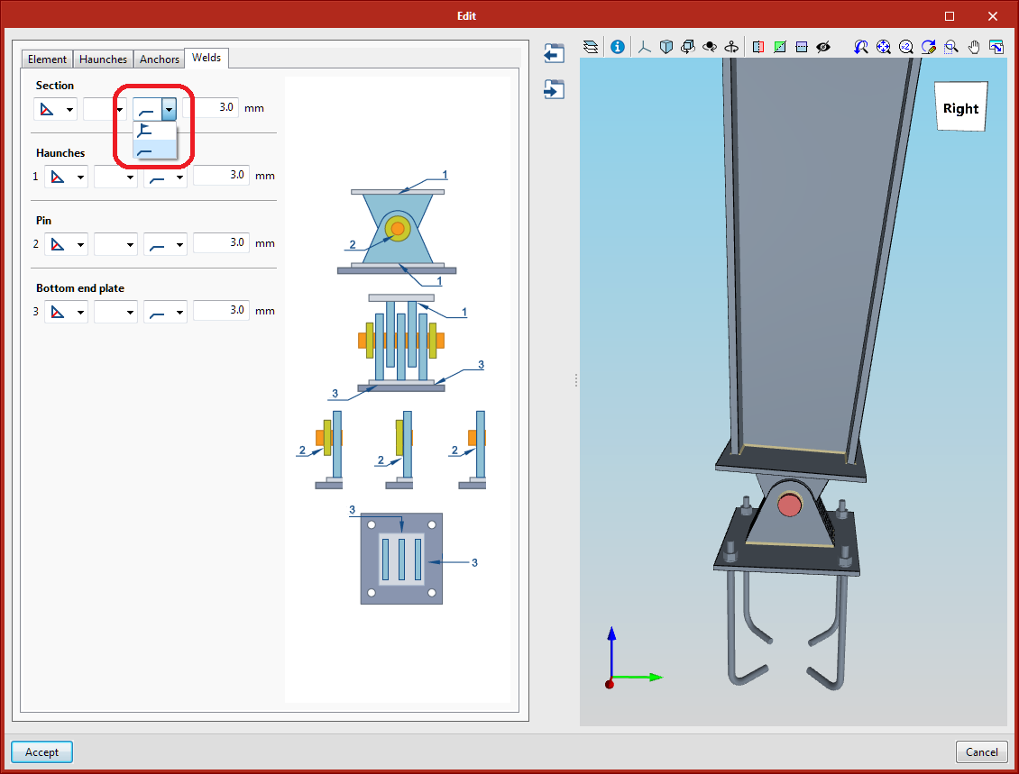
Grouping of elements depending on the location of the executed welds
The elements that are generated by the connections can now be grouped in parts that are manufactured in the workshop, depending on the position of the execution of the welds.
The welds can be executed on site or in the workshop. Elements that are connected with a workshop weld will form a single element.
For each connection that is available in the program, users can select the place of execution, where the default option is the workshop.
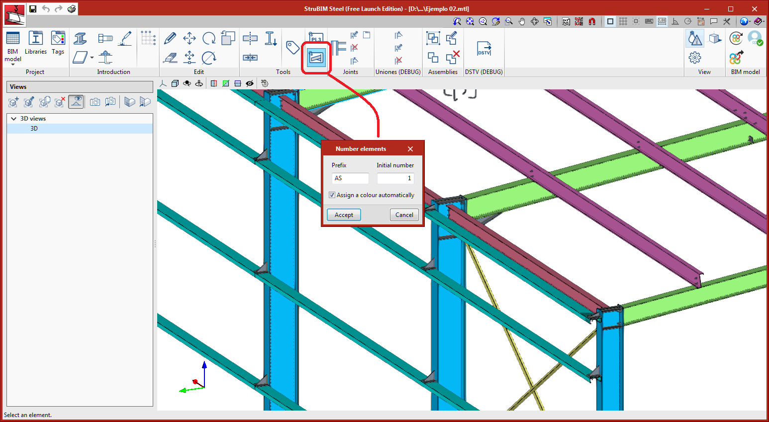
Element numbering tool
A new tool has been implemented to number the elements. Users can choose the prefix and initial number, as well as the option to assign a colour to each element automatically.
Identical elements will have the same assigned reference.
CYPELEC Electrical Mechanisms
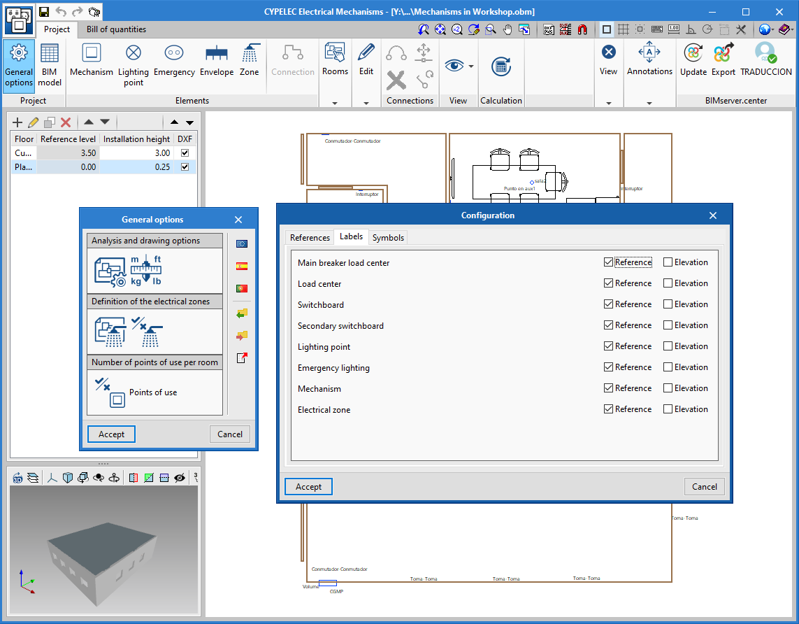
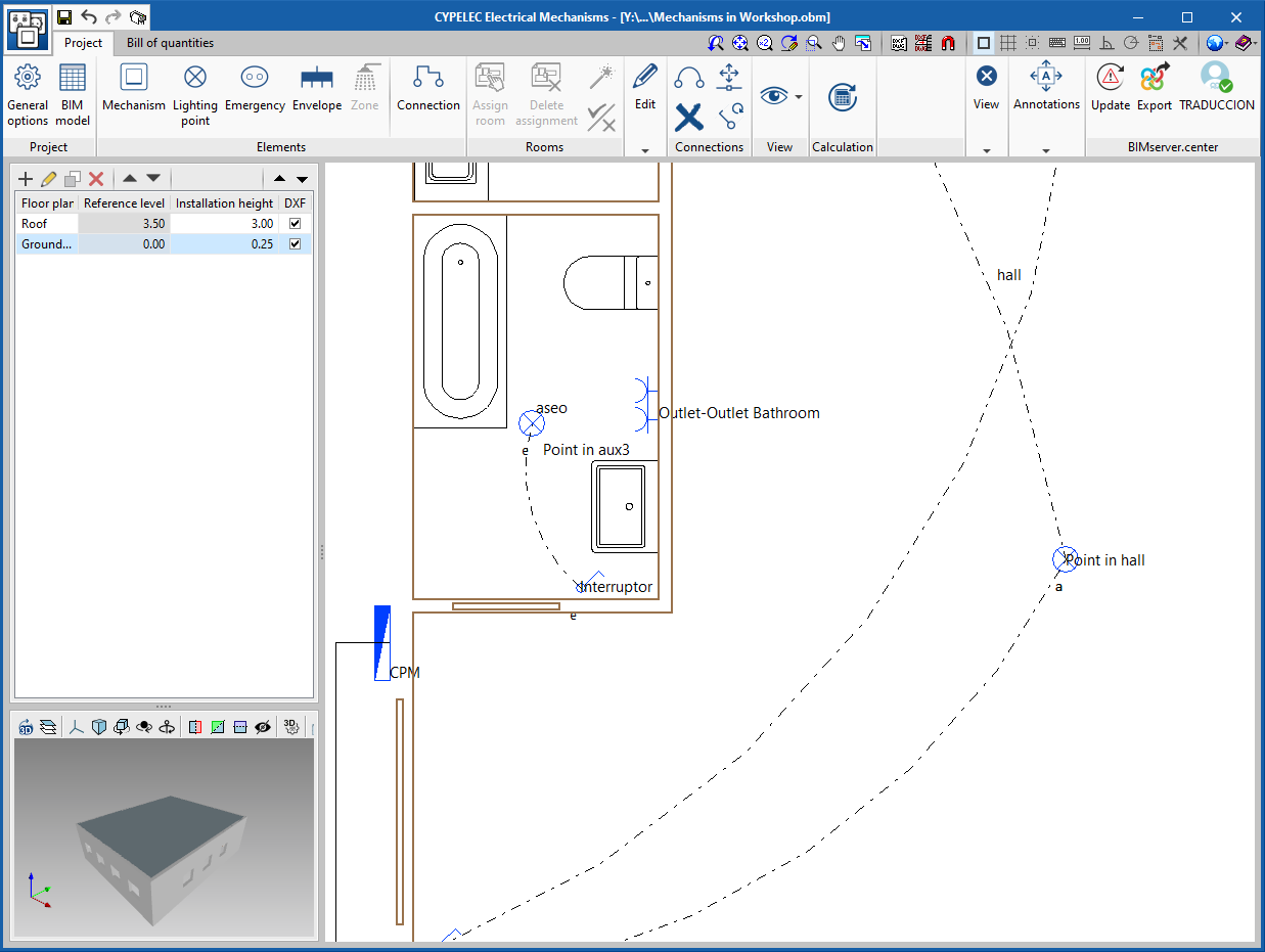
Representation options
A new functionality to represent labels in elements has been added.
In general options, the Representation options icon incorporates three tabs:
- References
Allows users to assign the default reference for the different elements. - Tag (new tool)
Allows, for each element, for users to make a customised selection of the properties that are to be represented on screen and later on the floor drawings. - Symbols
Allows users to edit custom symbols that can later be assigned to the different elements.
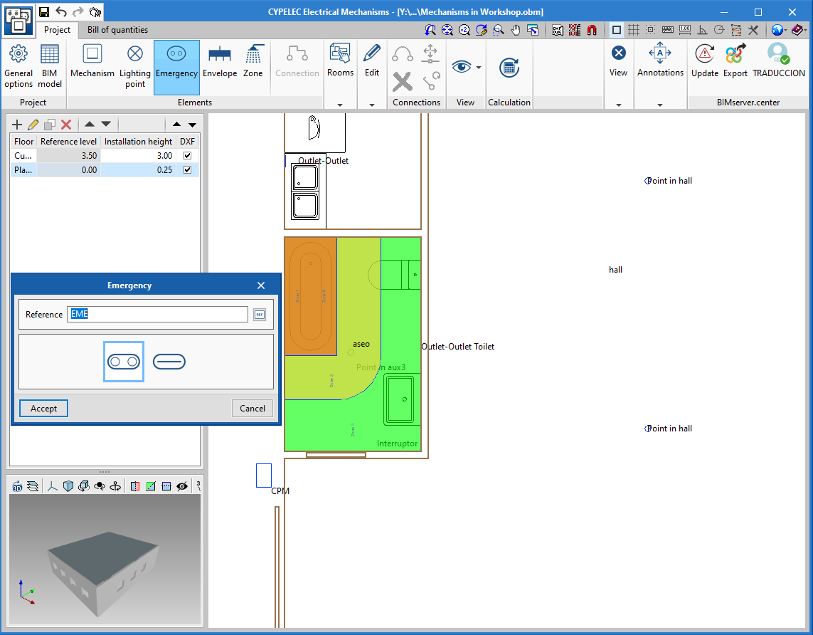
Emergency lighting
Users can now enter emergency lighting, thereby increasing the number of elements that can be entered into the program.
The lights are entered in a similar way as are light points and other electrical mechanisms.
CYPELEC Distribution
Quick connection between the pattress box and junction box
The quick connection tool between the lighting points and the junction box (located in the toolbar and labelled "Horizontal, to junction box") is extended to the selection of the pattress box. This way, time is saved in the connection, since, as well as being able to select lighting and emergency points, it is also possible to select the pattress boxes in which the switches are located.
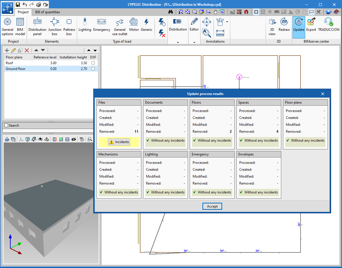
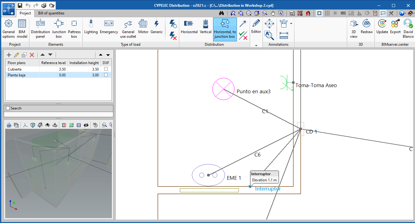
Import emergency lighting from the BIM model
Emergency lights could already be entered in CYPELEC Distribution. As of the 2021.c version, it is possible to read emergency lights that are contained in the BIM model, for example those from CYPELEC Electrical Mechanisms (which can also be entered in this version ). This improves the Open BIM workflow.
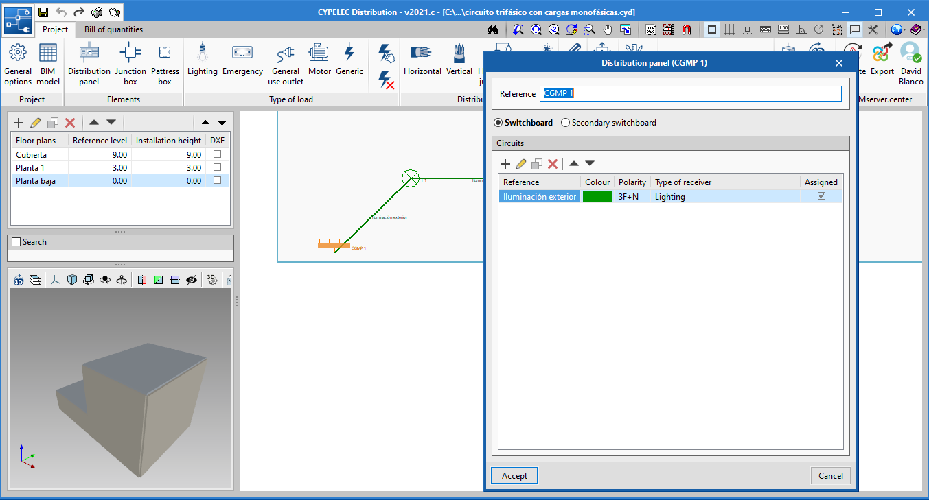
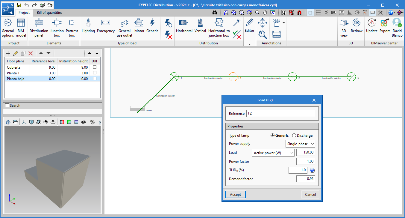
Distribution of a three-phase circuit with single-phase loads
CYPELEC Distribution allows for users to define the distribution of a three-phase circuit with single-phase loads. To define this distribution, the polarity of the circuit must be 3F+N and the supply of the loads single-phase.
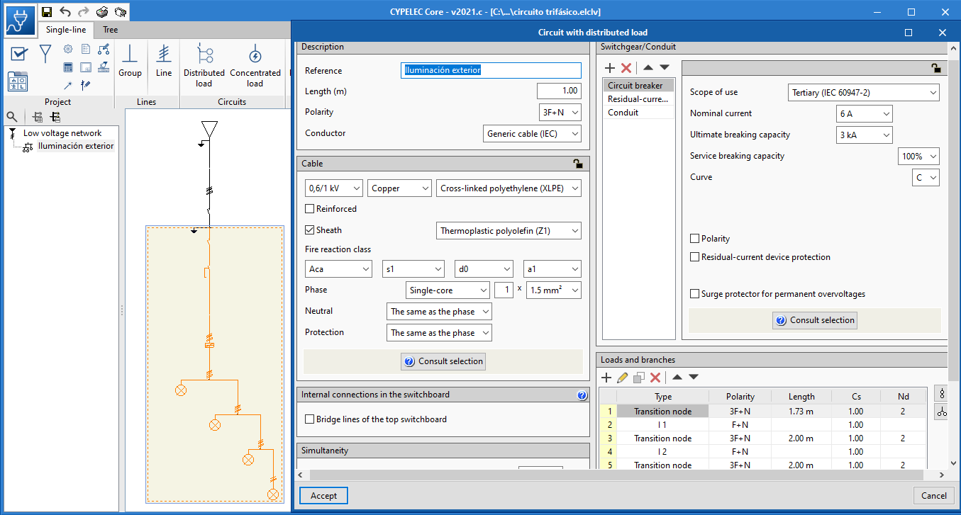
This circuit is represented in CYPELEC Core, CYPELEC REBT, CYPELEC NF and CYPELEC RETIE as a three-phase distributed circuit with single-phase loads connected along its path.
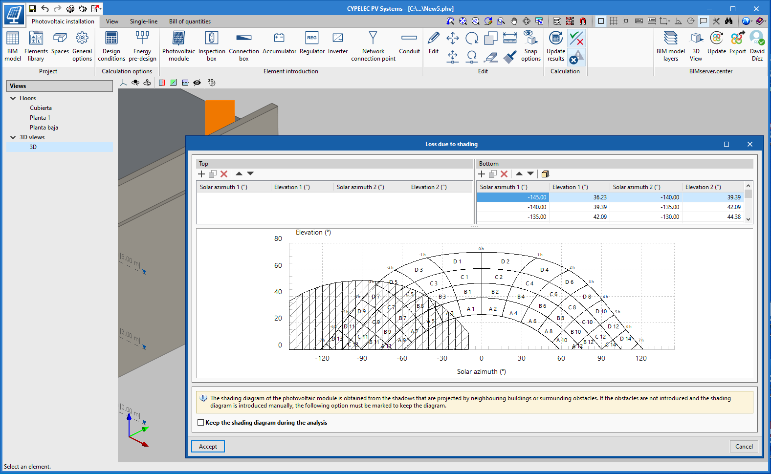
CYPELEC PV Systems
Generation of shadows of own construction elements
In the process that generates shadows on the solar collectors, the shadows that are generated by the building's own construction elements are taken into account. Illustrative examples of shadows produced by these elements are listed below:
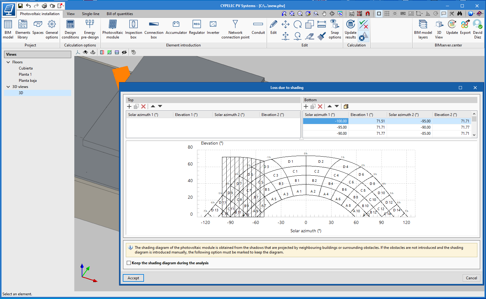
- Shadows of horizontal slabs.
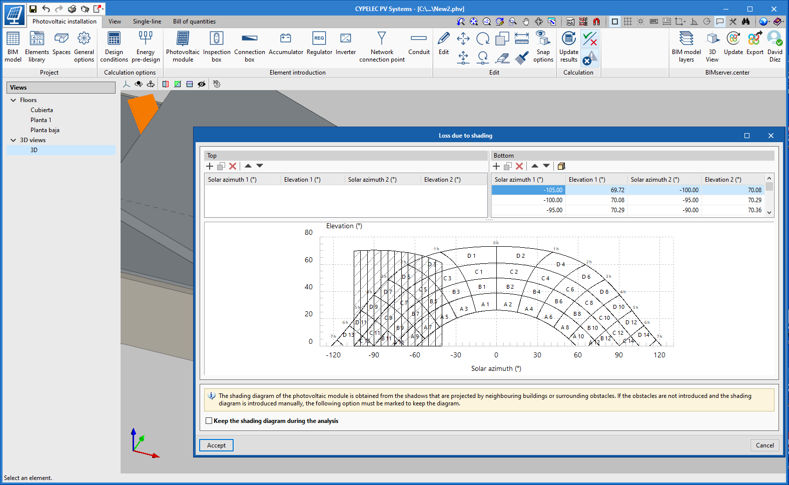
- Shadows of sloping roofs.
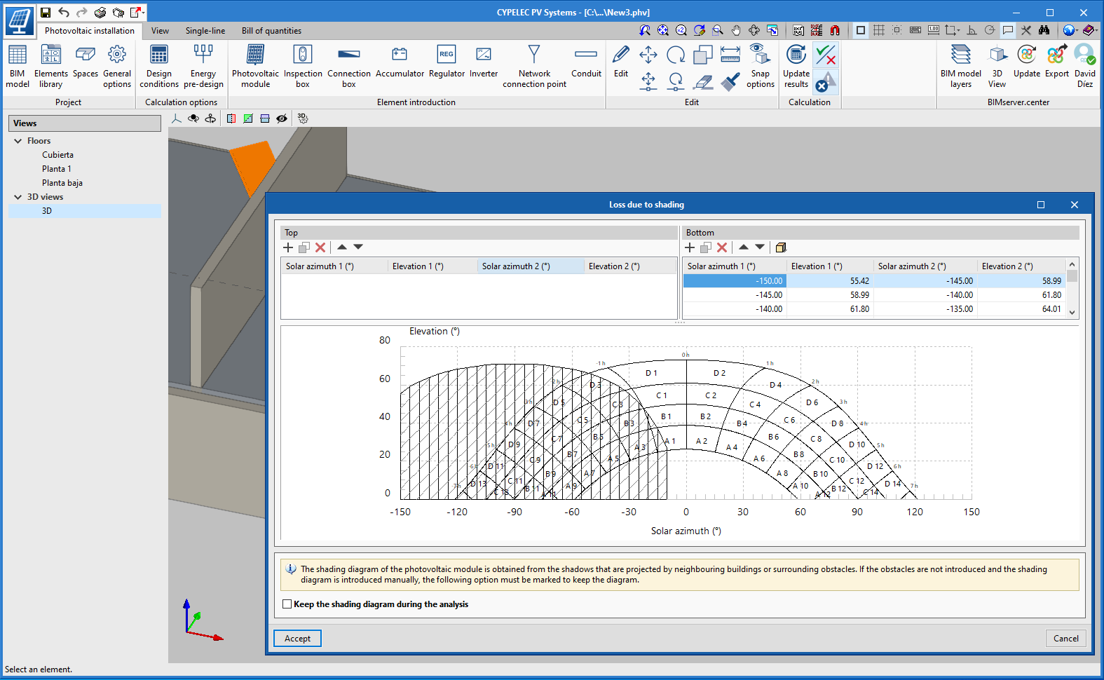
- Shadows of vertical walls.
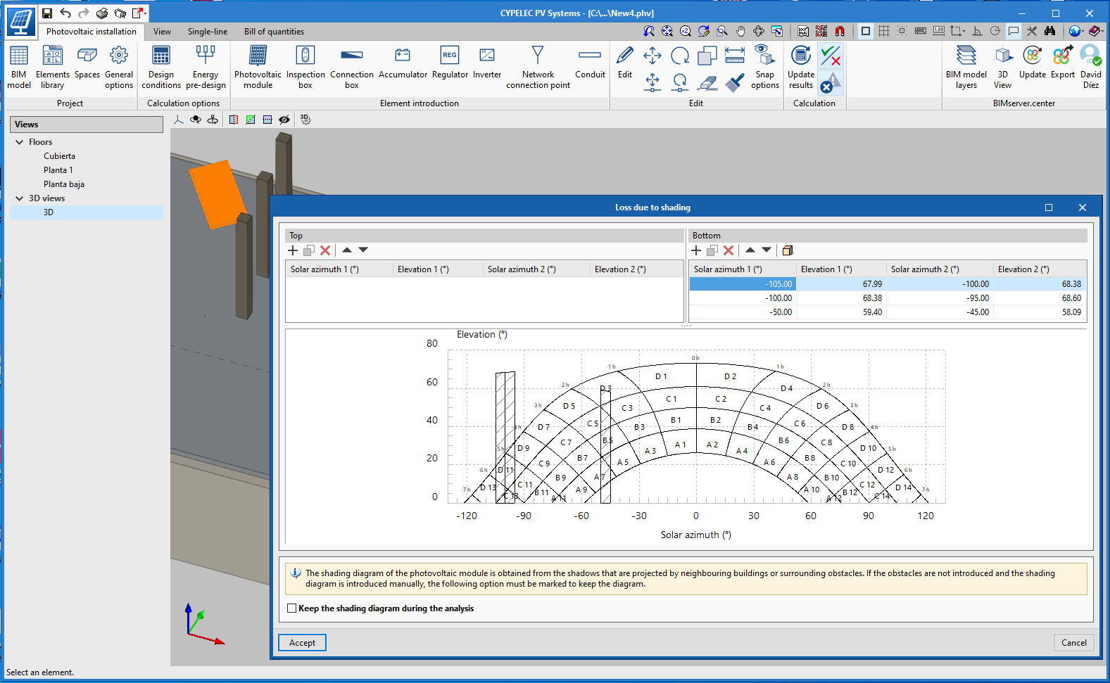
- Shadows of columns.
- Shadows of guardrails or parapets.
It is important to mention that for these elements to generate shadows it is essential that the BIM model be up-to-date and import the architectural model again.
CYPEFIRE Design
Bill of quantities tab
The "Bill of quantities" tab has been added to the toolbar of the "CYPEFIRE Design" application.
In the "Bill of quantities" tab, users have tools to generate and manage the bill of quantities of the installation that the program analyses. In this tab, users can extract the quantities of the model and, using that information, generate real job items. This process is carried out using a correspondence system between the elements that are measured on the design model and the concepts of the bill of quantities (mapping). This equivalency is stored in a local or network directory so that it can be expanded progressively and used in future projects.
To enter the prices of the project more easily, users can import complete databases and individual concepts from cost databases that have been developed in FIEBDC-3 (.bc3) format, such as those from the Construction Price Generator by CYPE.
The documents of the bill of quantities can be extracted in several reports (Quantities, Cost breakdown structure, Priced bill of quantities, Detailed bill of quantities, BoQ summary) which can be exported in HTML, DOCX, PDF, RTF and TXT format.
More information on the "Bill of quantities" tab in Open BIM applications of the project phase.
CYPEFIRE Hydraulic Systems
Automatic sizing
The analysis and design of an automatic sprinkler system can be quite complex. All the hydraulic design requirements that must be met by the different applicable regulations make the selection of the pipes one of the most complex tasks in the design of the installation.
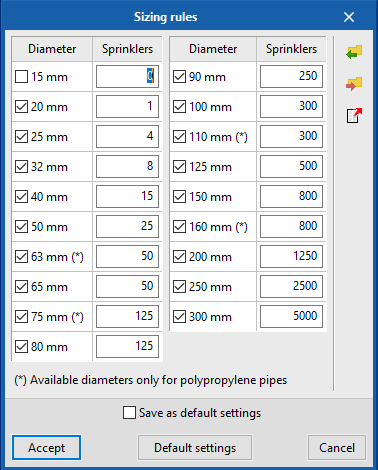
To facilitate this process, from the 2021.c version, "CYPEFIRE Hydraulic Systems" has the new "Automatic design" tool.
This tool can be configured by users in "General options > Design criteria". From this panel it is possible to edit the diameters to be used in the design and the maximum number of sprinklers that each diameter can supply before moving on to the next available diameter.
If users do not want to change the default data, the "design" tool will launch the diameter selection process and then the hydraulic analysis. This selection and hydraulic analysis process will end if no errors are found when the results that are obtained are compared with the requirements of the regulations. Otherwise, the process will be repeated until valid diameters are selected, to comply with the applied regulations.
Italsan product catalogue
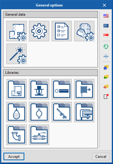
As of the 2021.c version, users will be able to work with CYPEFIRE Hydraulic Systems using Italsan catalogues. Specifically, using the products included in the NIRON RED system (polypropylene piping systems for fire protection installations).
In the "General options" panel, users can select the Italsan logo to import its catalogue (located under the regulations that are implemented in the application). Once imported, the sprinkler installation can be designed with all the available products, in accordance with the indications of this manufacturer.
CYPEHVAC Ductwork
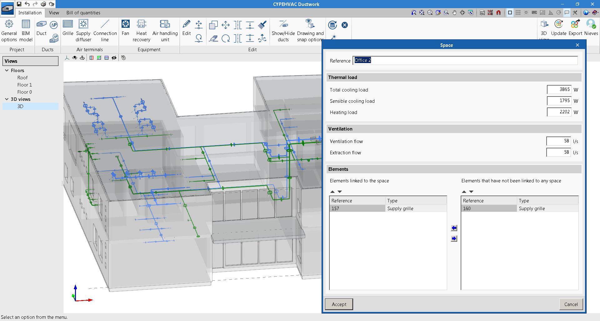
Incorporation of the thermal loads of spaces
Thermal loads have been incorporated in the spaces. Now, users can enter the loads manually or they can be read automatically from the BIM project to which the project is connected if it has this information.
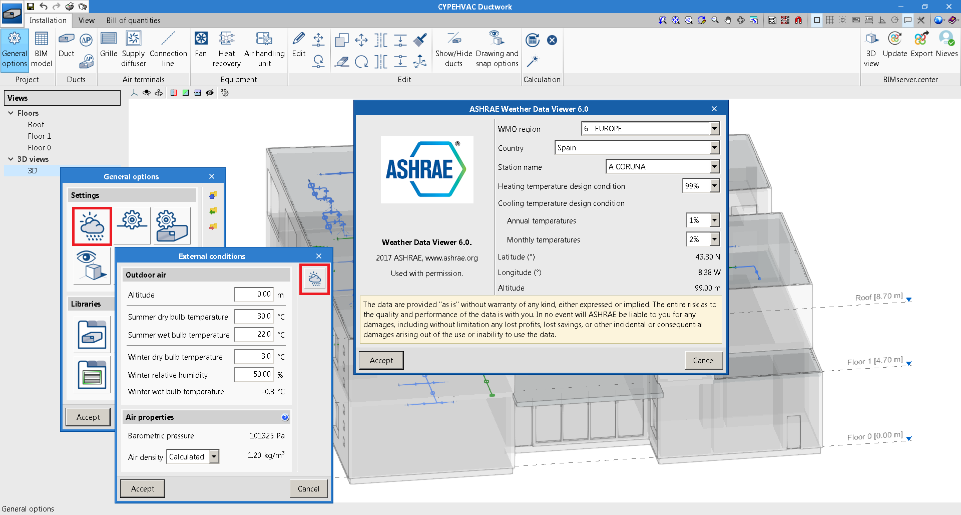
Incorporation of the ASHRAE weather database
The American Society of Heating, Refrigerating and Air-Conditioning Engineers (ASHRAE) climate database "ASHRAE Weather Data Viewer 6.0" has been added to CYPEHVAC Ductwork.
CYPETHERM LOADS, CYPETHERM Eplus, CYPETHERM RT2012, CYPETHERM RT2012 CNOA, CYPETHERM COMETH, CYPETHERM RTExistant, CYPETHERM RECS and CYPETHERM Fujitsu
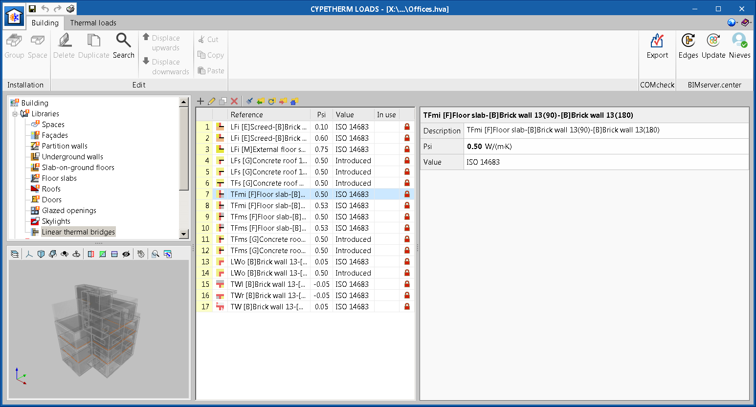
Export/Import the analysis and study of the thermal bridges
As of the 2021.c version, CYPETHERM LOADS, CYPETHERM EPlus, CYPETHERM RT2012, CYPETHERM RT2012 CNOA, CYPETHERM COMETH, CYPETHERM RTExistant, CYPETHERM RECS and CYPETHERM Fujitsu can import, from a BIM project that is located on the BIMserver.center platform, the analysis and study of the thermal bridges that any of them has exported to the project. This way, once the study has been carried out on one of them, it will be available to the rest without having to repeat it in each program.
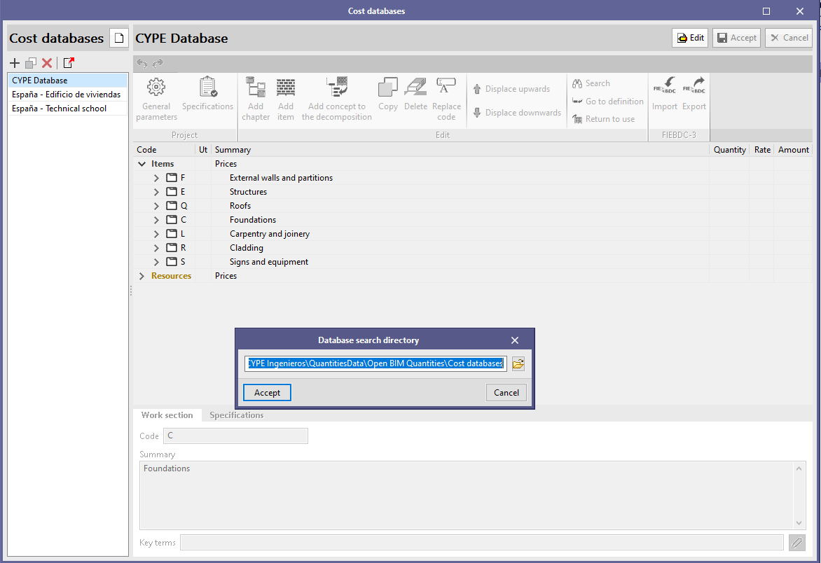
Open BIM Quantities and applications with the Bill of Quantities tab
Copy a cost database
Now it is possible to duplicate cost databases in the same way as is done with mapping files ("Bill of Quantites" tab) and the measurement criteria (Open BIM Quantities). When a cost database is copied, the documents that are associated with the concepts that make up the database ("Graphic information", "Attached documents" and "Specifications") will also be duplicated.
The cost databases can be managed using the corresponding button, which is located in the Open BIM Quantities toolbar and the "Bill of Quantities" tab, in the applications that include it.
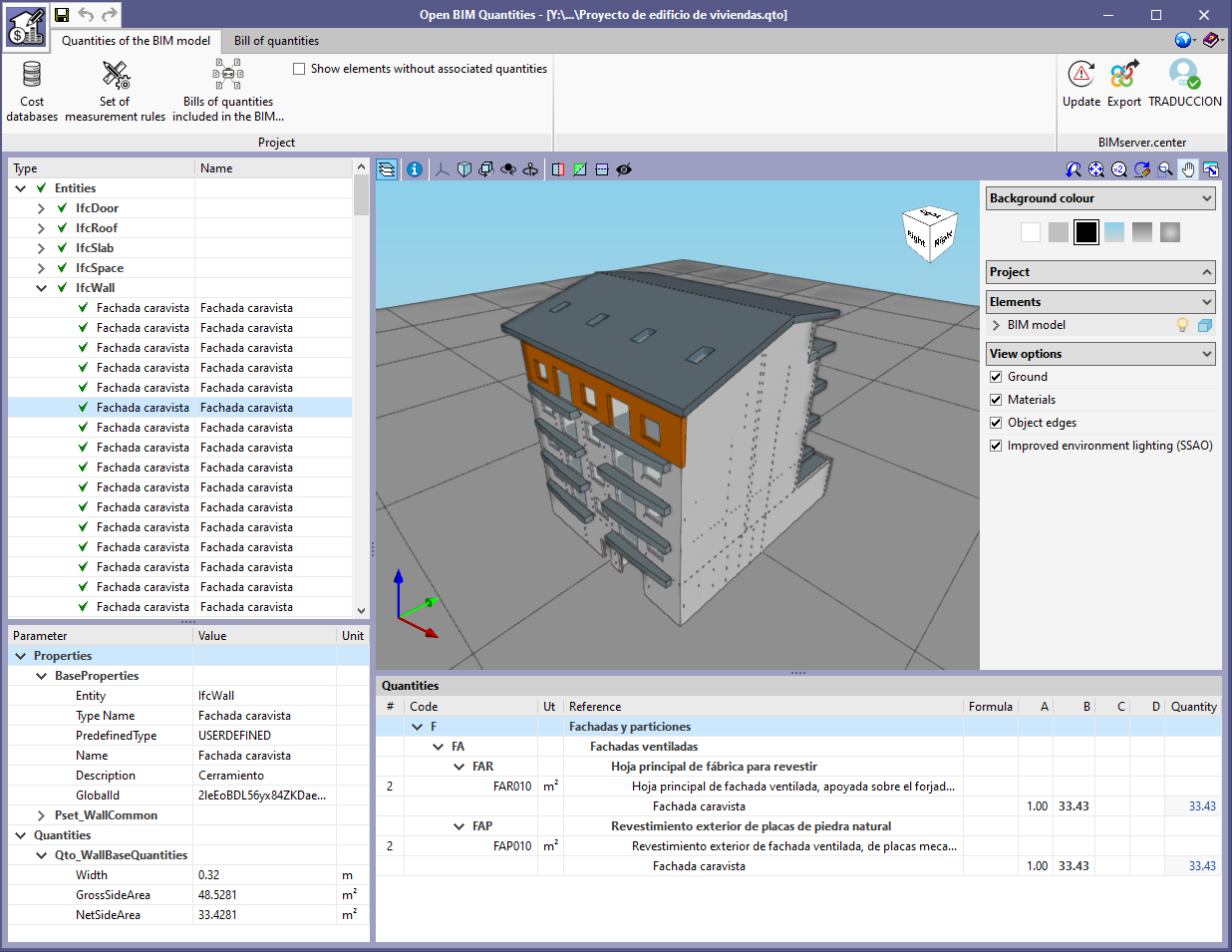
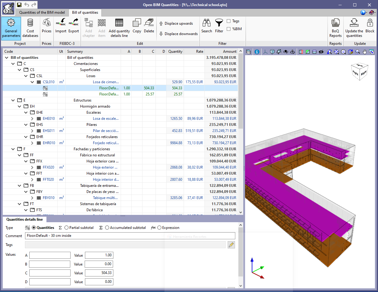
Open BIM Quantities
Example projects
Two example projects have been included: "Proyecto de edificio de viviendas" and "Technical school" with their corresponding measurement rules and cost databases.
Applications with the Bill of Quantities tab
More currency codes available
The following references have been added in the help tool to fill in the currency code, within the general parameters of the project:
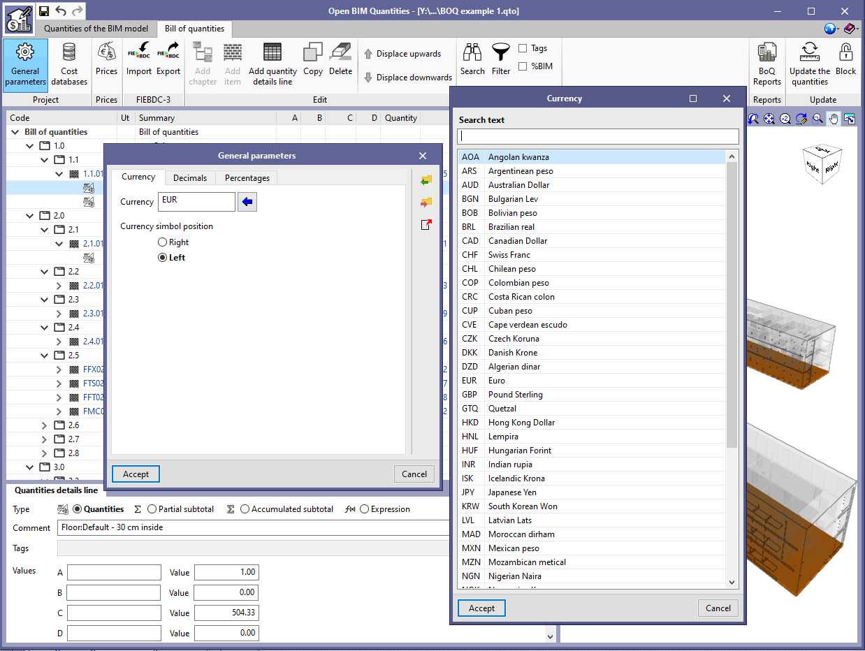
- AOA - Angolan kwanza
- ARS - Argentine peso
- BOB - Bolivian peso
- BRL - Brazilian real
- CHL - Chilean peso
- COP - Colombian peso
- CRC - Costa Rican colon
- CUP - Cuban peso
- CVE - Cape Verdean escudo
- DZD - Algerian dinar
- GTQ – Guatemalan quetzal
- HNL – Honduran lempira
- INR - Indian rupee
- MAD - Moroccan dirham
- MXN - Mexican peso
- MZN - Mozambican metical
- NGN - Nigerian naira
- PEN - Peruvian nuevo sol
- PYG - Paraguayan guarani
- UYU - Uruguayan peso
- VEF - Venezuelan bolivar fuerte
- XAF - Central African CFA franc
- XOF - West African CFA franc
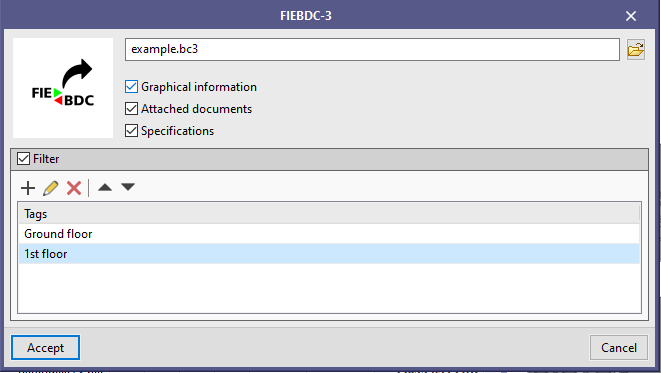
Tag filter to export to FIEBDC-3 (.bc3)
A concept filter based on tags has been added, and is available in the configuration panel when exporting the bill of quantities to a file with FIEBDC-3 format (.bc3). When a tag is added to the filter list, only job items containing detail lines to which that tag has been assigned will be included.
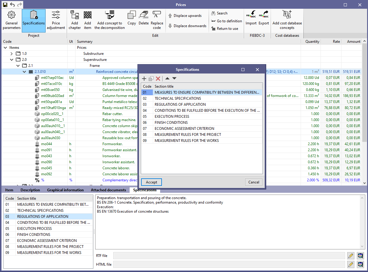
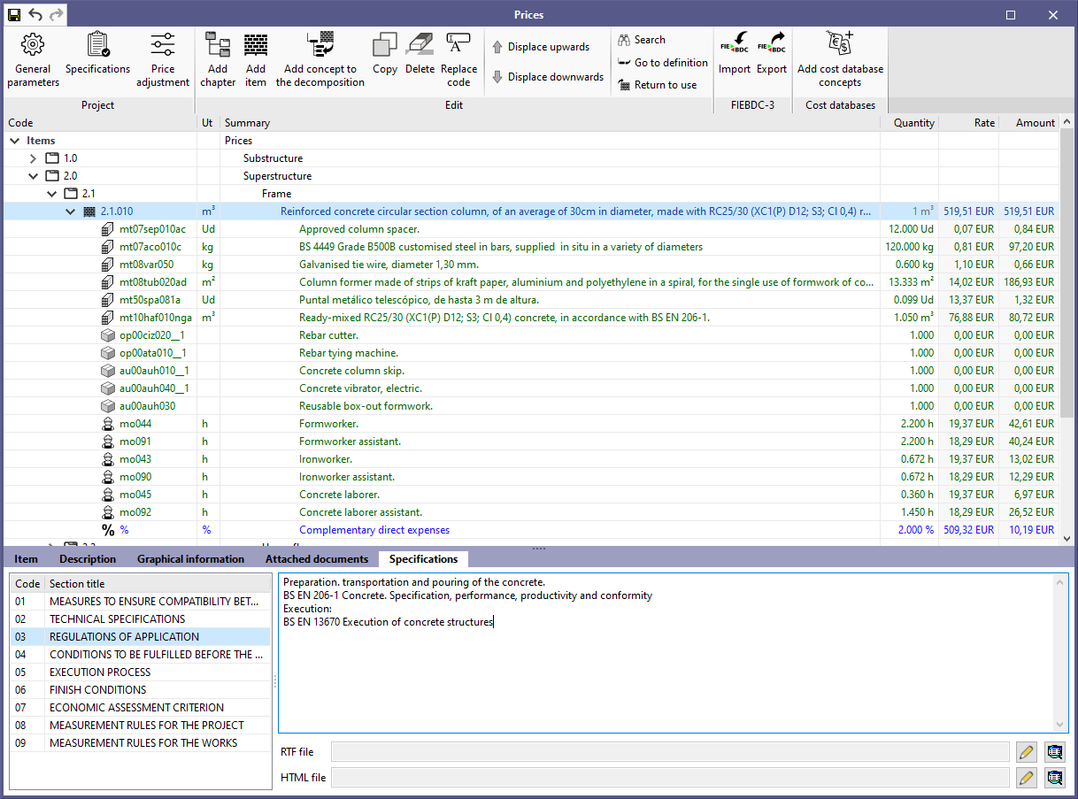
Specifications
As of the 2021.c version, users can enter the information related to the tender specifications in the prices of a project or in a cost database.
Using the "Specifications" option that is contained in the "Project" group of the toolbar, users can define the codes of the sections of each specification, as well as their corresponding labels. Once the structure has been established, the data that refers to each section in each concept (chapter, job item or unit price). It should be noted that, in addition to a text with the contents of the section, users can attach an RTF file and/or an HTML file.
The specifications have been incorporated into the import and export process of the bills of quantities and cost databases in FIEBDC-3 format. For this, as is indicated in the specification of the standard, the -L, -Q and/or -J registers are used. As was done with the "Graphic information" and the "Attached documents", the reading or writing of the specifications is optional and can be controlled from the same configuration panel.
It is important to bear in mind that the FIEBDC-3 format is used by CYPE's Open BIM applications that include the "Bill of Quantities" tab to transmit their data to Open BIM Quantities via the BIMserver.center platform. Consequently, the specifications that are generated in other applications can also be read in Open BIM Quantities to consolidate them and obtain the full project specifications.
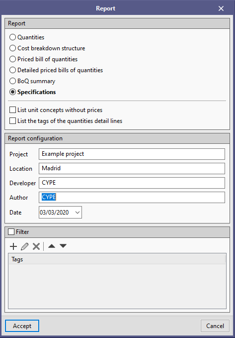
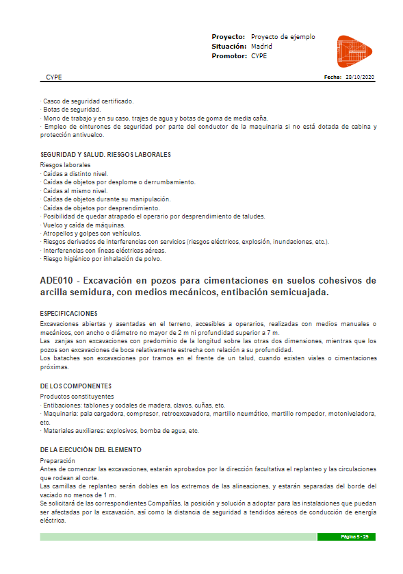
Finally, a new document has been added to the "Bill of quantity reports" in order to create the "Specifications" of the project. When it is generated, only concepts that have information about a section of the specifications will be listed, together with the content that has been entered.
Arquimedes
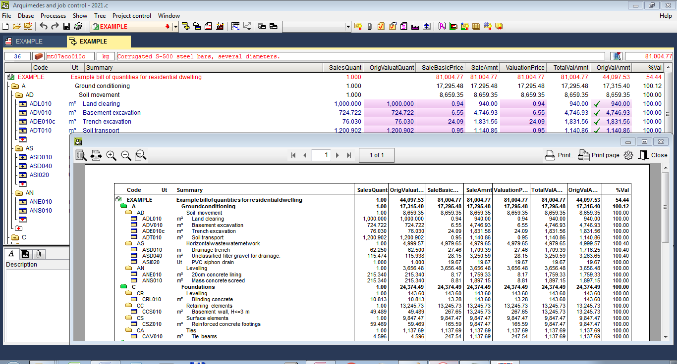
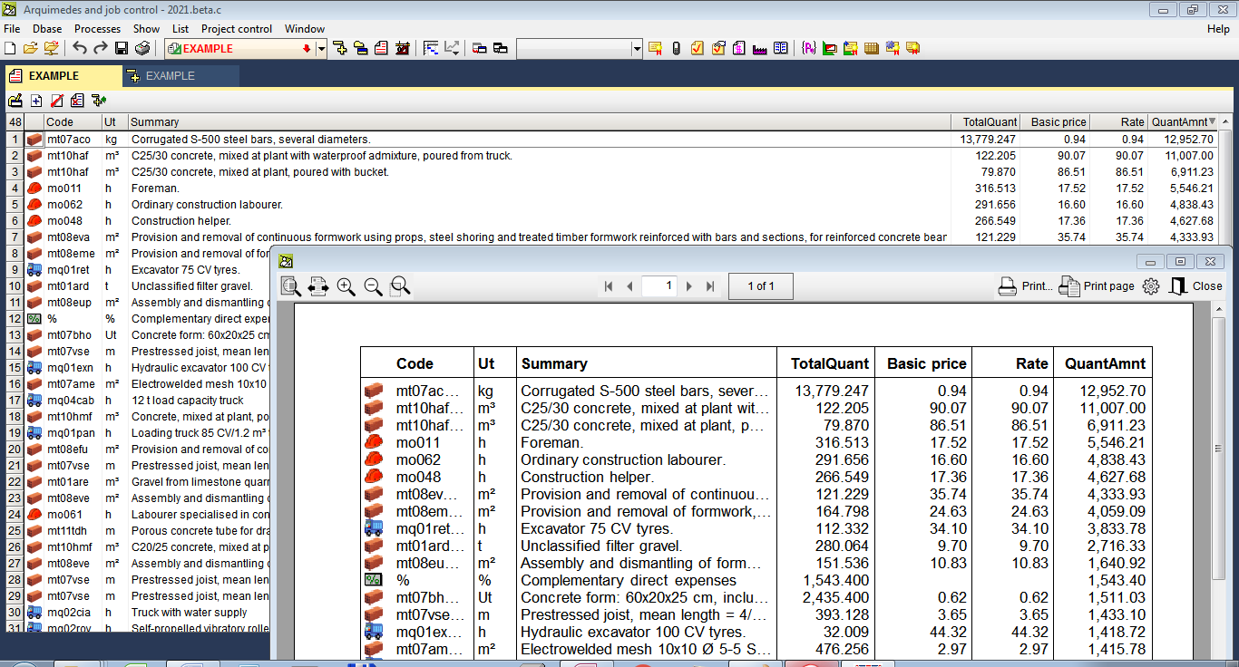
Print contents of the "Decomposition tree" and "Concept list" views
This tool allows users to easily print, by means of a template, any column composition that is contained in the work area of the "Decomposition tree" and "List of concepts" windows. This way, the work that must be carried out is simplified because users do not have to create or modify an existing report template to print the contents of these windows.
This tool is activated from the "Print view contents" option of the "Tree" and "List" menus, or by pressing the right button of the mouse on the tab of the view (in tree or in list) of the database from which the contents are to be printed.
The "Print view contents" dialogue box contains several options:
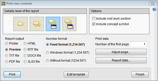
- When it is activated from the "Decomposition Tree" window
- The level of detail of the report to print:
 Only chapters that are at the first level.
 All chapters.
 All chapters and their job items.
 All chapters together with their job units and the unit concepts of the job units.
- The contents of the root chapter and the symbol that represents the type of concept can be included.
- The level of detail of the report to print:
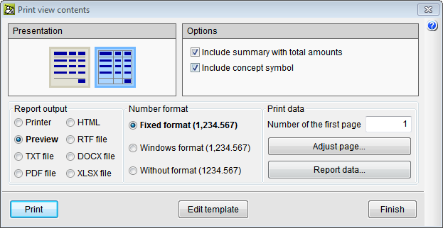
- When it is activated from the "Concept list window"
- The level of detail of the report to be printed can be selected:
 The report without column lines.
 The report with column lines.
- A summary with a totals line and the symbol that represents the type of concept can be included.
- The level of detail of the report to be printed can be selected:
The "Print view contents" tool creates a report template automatically to be able to print the columns of the "Decomposition tree" or "Concept list" window. The template can be modified by users to adapt it to their own style.
Bill of quantities of Revit models
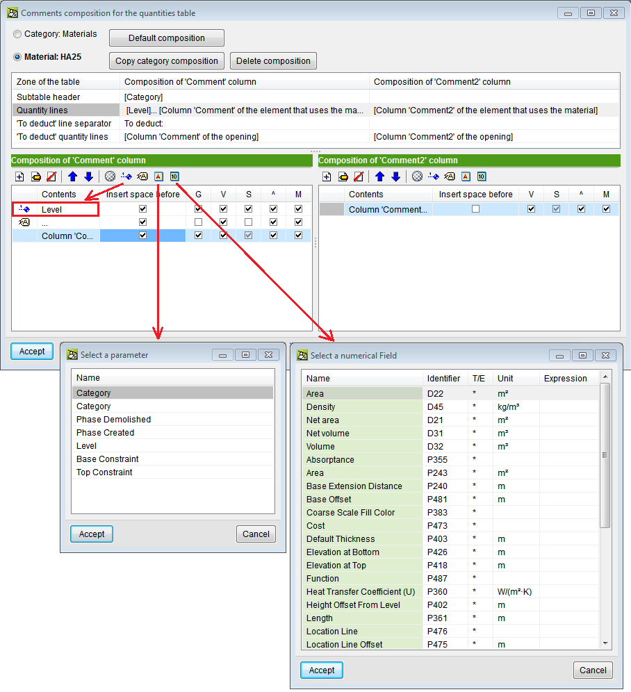
More alphanumeric parameters and numerical fields of material examples
The "Add level" tool is included and there are more available alphanumeric parameters and numerical fields of material examples for comments when measuring by material quantities.
Users can now configure the comments of the quantity lines of items that use materials, by means of alphanumeric parameters or numerical fields. The alphanumeric parameters are available in the items that use that material. Numerical fields were already used to carry out the calculation combination.
Return to the 2021 version download area
Tel. USA (+1) 202 569 8902 // UK (+44) 20 3608 1448 // Spain (+34) 965 922 550 - Fax (+34) 965 124 950