
New programs and modules
New features of existing programs
- Installation of CYPE programs
- Open BIM BOSCH, Open BIM DAIKIN, Open BIM FUJITSU, Open BIM MIDEA, Open BIM KAYSUN, Open BIM PANASONIC and Open BIM TOSHIBA
- Open BIM MOVAIR
- Open BIM KAYSUN
- Open BIM PANASONIC
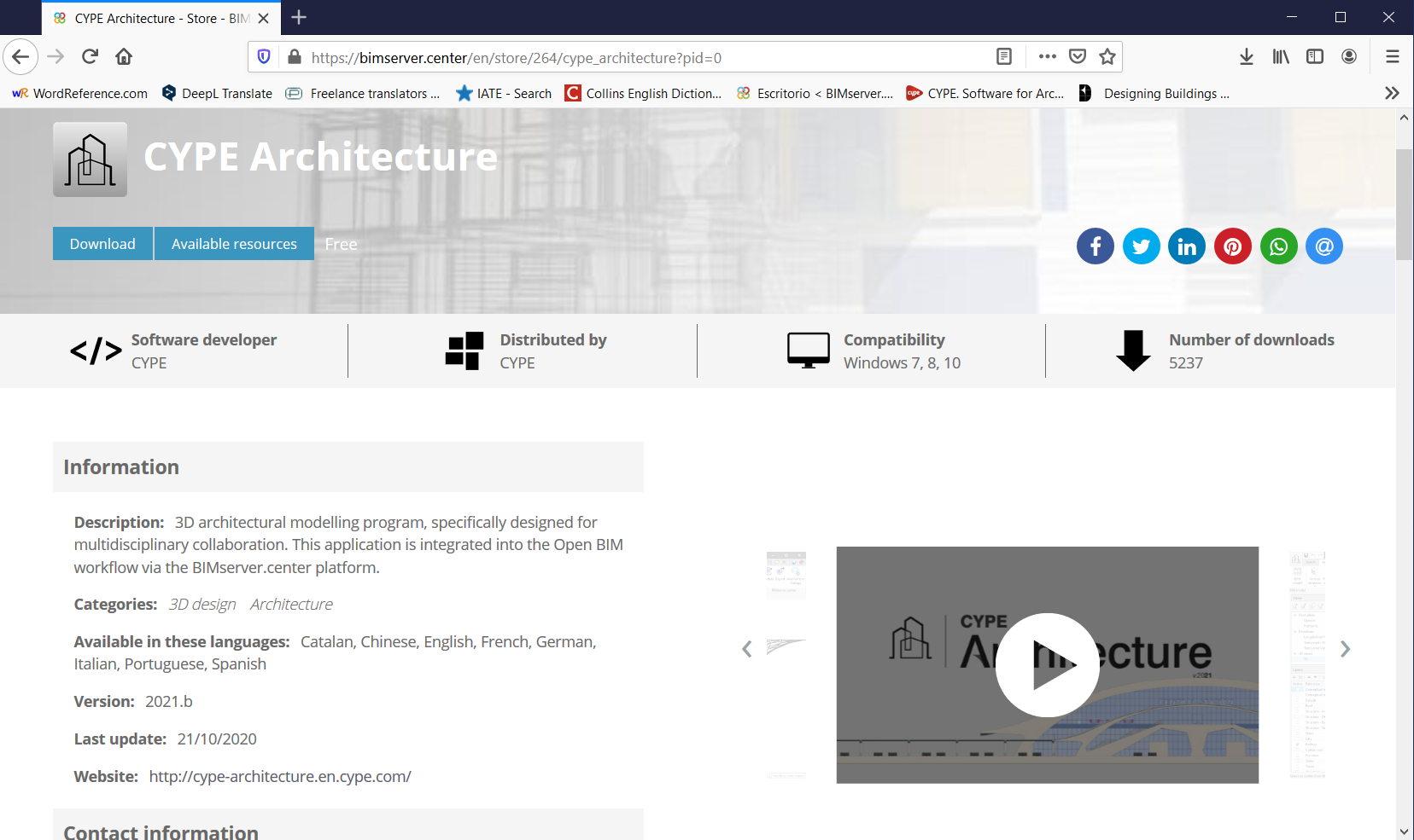
- CYPE Architecture
- IFC Builder
- Open BIM Construction Systems
- CYPECAD
- CYPE 3D
- StruBIM Steel
- StruBIM Shear Walls
- CYPELEC Distribution
- CYPETEL Systems and FAAST IT
- CYPETEL Schematics, CYPETEL Systems and FAAST IT
- FAAST IT, CYPETEL Project ITED-ITUR, CYPETEL Wireless
- CYPEPLUMBING Sanitary Systems and CYPEPLUMBING Water Systems
- CYPEPLUMBING Sanitary Systems
- CYPEPLUMBING Water Systems
- CYPEHVAC Ductwork
- Open BIM Quantities and Elodie by CYPE
- Arquimedes and Job control
New programs and modules
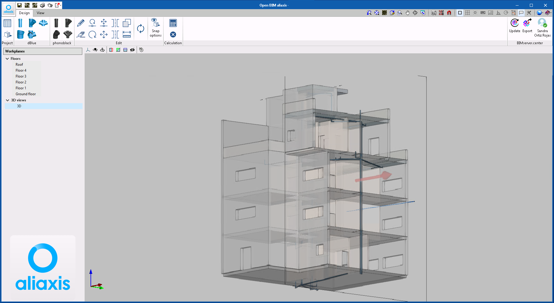
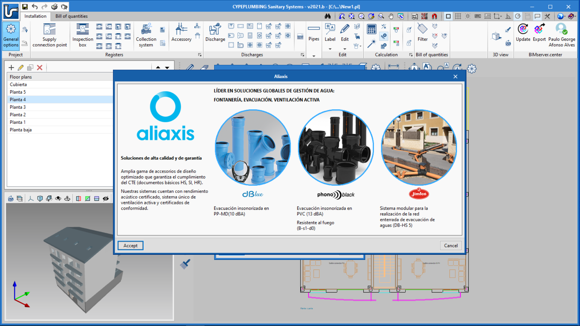
Open BIM aliaxis
"Open BIM aliaxis" is a free application to model wastewater systems that belong to the manufacturer "aliaxis".
The program is integrated into the Open BIM workflow, which means it is able to read the geometry of the building that has been created by any geometric generator that works with the IFC standard, and can participate in an integrated way in the Open BIM workflow via the BIMserver.center platform.
New features of existing programs
Installation of CYPE programs
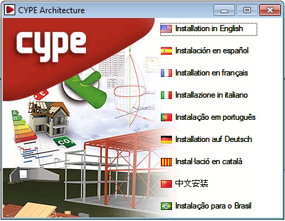
As of the 2021.b version, all CYPE programs are installed using download managers.
Download managers are files with ".exe" format which are downloaded from the "Store" section of the BIMserver.center platform or from the Download area of the CYPE website (depending on which program is to be installed). Each program has its own Download manager.
Using the download managers, users can download and install the chosen program in one of the languages to which the program has been translated, without having to decompress any files with "zip" file decompression software.
Furthermore, with the Download managers, BIMserver.center platform programs can be installed in languages with non-Latin alphabets, such as "CYPE Architecture" or "Open BIM Layout", which can be installed in Chinese.
The Download manager of the complete program package that is installed from the CYPE webpage (http://downloads.en.cype.com/) has been available since the 2014 version. Now, all CYPE programs, including those on the BIMserver.center platform, are installed using Download managers.
Open BIM BOSCH, Open BIM DAIKIN, Open BIM FUJITSU, Open BIM MIDEA, Open BIM KAYSUN, Open BIM PANASONIC and Open BIM TOSHIBA
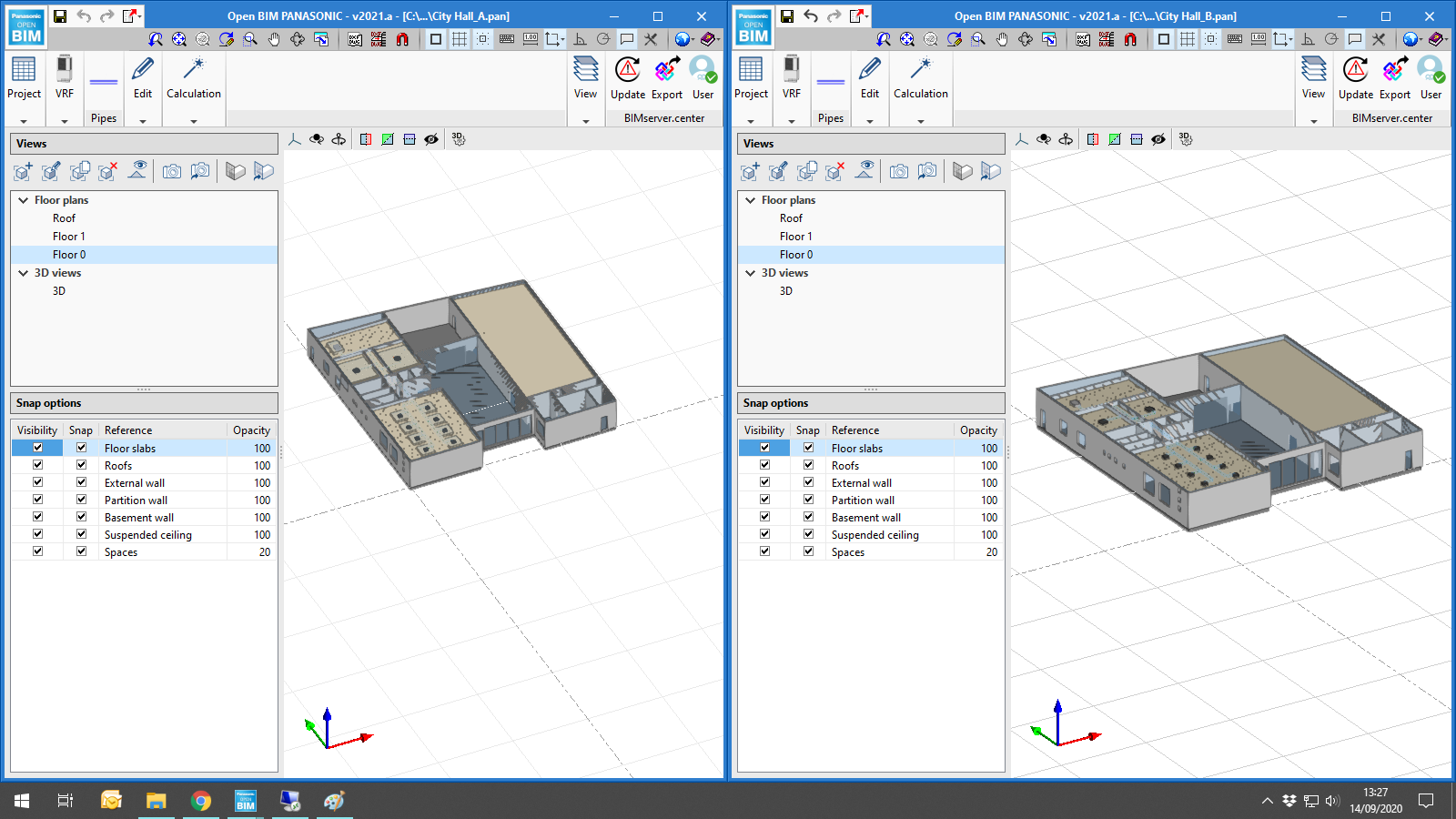
Simultaneous opening of several program sessions
Now users can open the program several times simultaneously, and so, work on several different files.
Open BIM MOVAIR
Duct checks
As of the 2021.b version, the program verifies whether the ducts that have been entered in the application have the same position and properties as those specified in the project of the BIMserver.center platform, to which Open BIM MOVAIR is connected. The position and properties of the ducts may be available in the BIM project if they have been exported previously by an application such as CYPEHVAC Ductwork.
Open BIM KAYSUN
Program interface improvements
The icons have been updated and their position on-screen can now be customised by users. By clicking on any group of elements (VRF and edit), its contents appear in a panel. By pressing on the pin, its position changes to indicate that the position of the panel has been fixed. Additionally, if the panel is dragged to the edge of any of the four sides of the workspace, the appearance of the cursor hand changes and, if users let go of the primary mouse button at that moment, the panel remains attached to that edge.
Open BIM PANASONIC
Air-source heat pump equipment
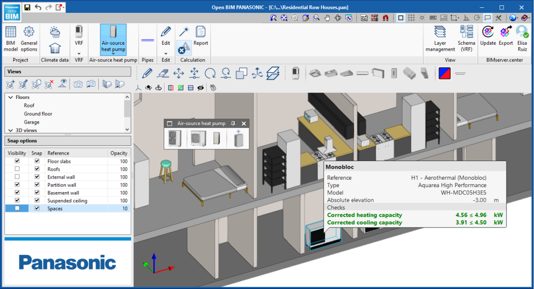
Mono-bloc and bi-bloc air source heat pumps have been added. When they are placed on a space that belongs to a thermal zone that has been previously analysed with CYPETHERM LOADS, Open BIM PANASONIC will read the thermal load of the zone and will include it in the air-source heat pump panel as the value of the required capacity. Nonetheless, if the loads have been calculated using CYPETHERM LOADS, users can type the capacity to be covered with the machine in the cell and close the lock.
After the design process, Open BIM PANASONIC reads the outdoor design temperatures and the indoor design conditions, and calculates the corrected capacity of the machine when it operates under these conditions. During the design process, the program selects the first equipment set that can manage the required load.
Furthermore, in the case of bi-bloc units, Open BIM PANASONIC controls if the length of the pipe exceeds that which is allowed for each model, or if the elevation change between the outdoor unit and the indoor unit is out of range.
The program generates a report with the basic data of each unit.
Communication with CYPETHERM HE Plus
As of the 2021.b version, Open BIM PANASONIC communicates with the official tool, CYPETHERM HE Plus using the Open BIM workflow via the BIMserver.center platform.
Once the system has been designed in Open BIM PANASONIC, it is exported to a BIM project that is located on the BIMserver.center platform. Using the CYPETHERM HE Plus energy simulation program, the changes in the BIM project of the model that is generated by Open BIM PANASONIC can be seen. If the model is updated in CYPETHERM HE Plus, the VRV and air-source heat pump systems will appear incorporated in their corresponding location: the outdoor units in "Air conditioning equipment" and the indoor units in each associated zone.
Program interface improvements
In the information that Open BIM PANASONIC displays in the tooltips after the analysis, cooling data is represented in blue and heating data in red.
Furthermore, the position of the on-screen icons can now be customised by users. By clicking on a group of editing elements, its contents appear in a panel. By pressing on the pin, its position changes to indicate that the position of the panel has been fixed. Additionally, if the panel is dragged to the edge of any of the four sides of the workspace, the appearance of the cursor hand changes and, if users let go of the primary mouse button at that moment, the panel remains attached to that edge.
In the diagram that Open BIM PANASONIC generates automatically, the representation of the equipment is a reflection of the real models. Furthermore, the branches that the program generates automatically are now represented using a cone in the 3D view.
CYPE Architecture
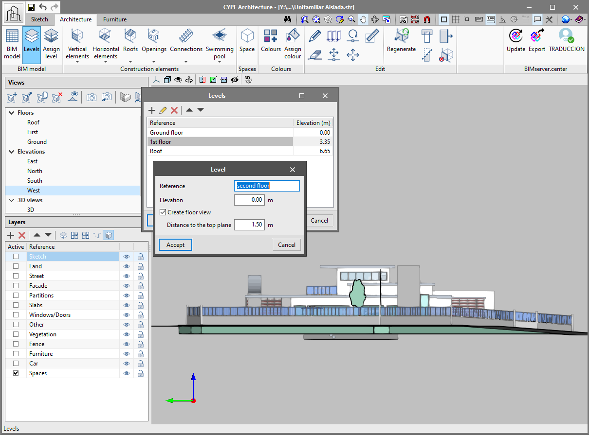
Include levels
The Program, CYPE Architecture, now has levels. The levels allow users to identify the main heights of the building, which are generally, the floor levels. The levels are fundamental for the architectural model to be read correctly in the other applications of the Open BIM workflow.
The levels are created in the "Architecture" tab using the "Levels" button. The main reference levels have to be added in the project using the "+" button. When a new level is created, the program asks if a view of the associated floor is to be created automatically.
A level can also be associated with a plan view from the "Views" panel. It is advisable to associate the levels with the plan views, this way all the elements that are placed in the view are associated directly with the level.
It is recommended to assign the corresponding level to all the elements of the "Architecture" tab.
Tag elements
Tags allow users to group elements of the same type. Tags are fundamental for the architectural model to be read correctly in the other applications of the Open BIM workflow.
When elements are entered in our model, they must be assigned a tag, which will then allow users to view them grouped in the other Open BIM programs of the BIMserver.center platform.
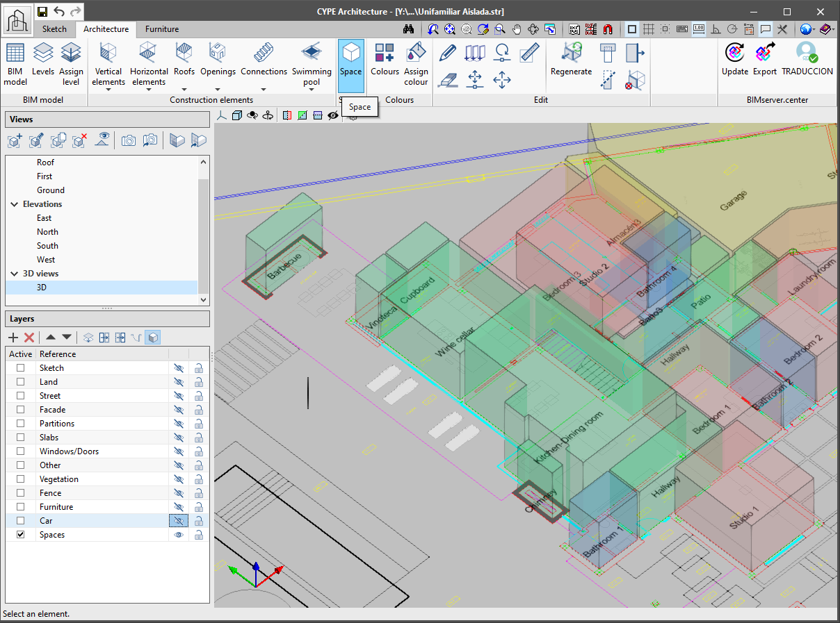
Assign spaces
Spaces allow users to delimit the different rooms of the architectural model. It is essential to define spaces in order to, for example, obtain measurements or perform thermal and acoustic calculations. Additionally, spaces are fundamental reference and representation elements in the Open BIM workflow.
Spaces are defined using a polyline and a height.
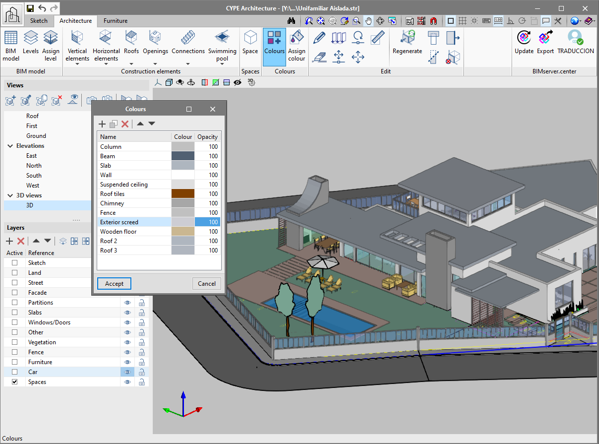
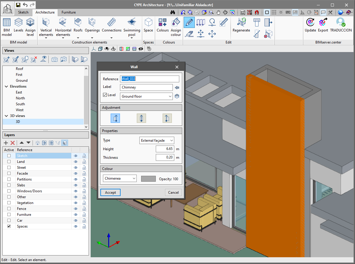
Apply colours to the architectural elements
All the elements of the "Architecture" tab allow users to define colours. There are two ways to define colours for an element.
There are two new buttons, "Colours" and "Assign colour" to define the colour of the more generic elements (walls, floors, columns, beams). The program, by default, creates a list of colours for the elements mentioned above. The default colours can be modified using the "Colours" button. Furthermore, users can create new colours using this button, which can be assigned later on to the elements of the "Architecture" tab.
To assign a colour, simply choose it from the drop-down list in the configuration panel when entering these elements.
To assign the same colour to several elements at the same time, use the "Assign colour" button with which multiple elements can be selected.
Improved "Curtain wall" functionality
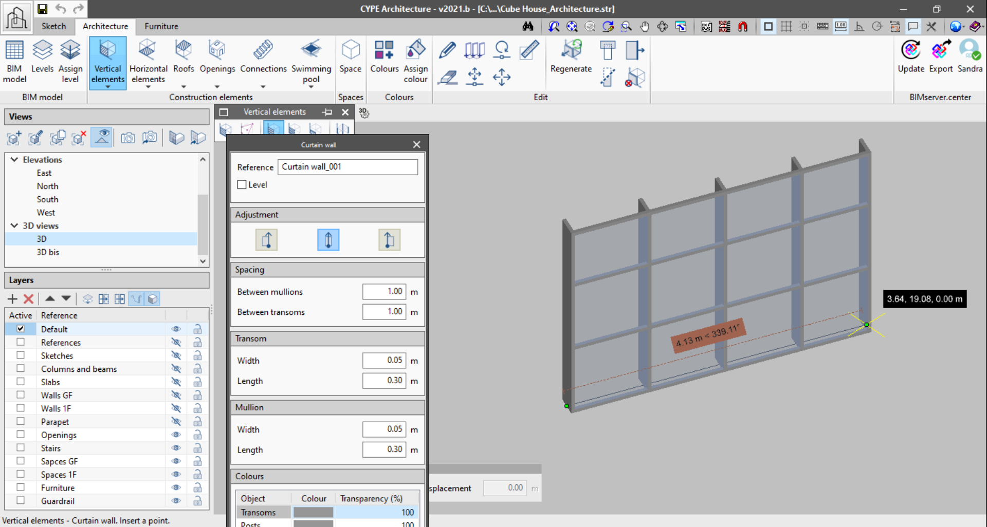
The "Curtain wall" functionality now includes:
- Adjustments when drawing the wall
It can be drawn from the middle, right or left. - Generation of the curtain wall as it is developed
The previous version of the curtain wall only generated complete modules. With this version, the curtain wall is generated as users extend the second point. This way, split modules can be generated. - Preview of the curtain wall
Now, the curtain wall displays a preview of the wall with a fixed height of three modules, to allow users to preview the wall while they are entering it in the program.
Improvements when exporting to BIMserver.center
Building models exported individually
From now on, three different models, generated by CYPE Architecture, can be found in the BIM model of the project that is located on the BIMserver.center. These are the model of the Sketch, the Architecture and the Furniture. This way, users can view their project more easily.
Sketch exported in "DWG 3D" format
The program will automatically export the elements of the "Sketch" tab to "DWG 3D" format. This format can be used later on in other programs in the Open BIM workflow, such as in StruBIM CYPE 3D.
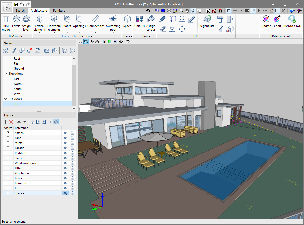
New project example
A new project example has been generated with all the new features of the program. In it, users can view spaces, tags, levels and the new building model painted with colours. We recommend users to open this new project if they wish to inspect the new features of the program.
IFC Builder
Only available on the BIMserver.center platform
As of the 2021.b version, the application, IFC Builder, will be available exclusively on the BIMserver.center platform. Therefore, it will not be installed with the software package that is downloaded from CYPE’s website.
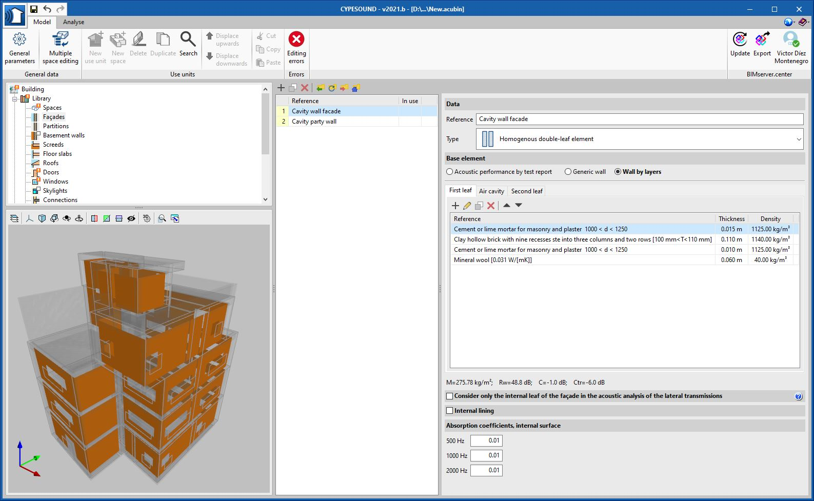
Open BIM Construction Systems
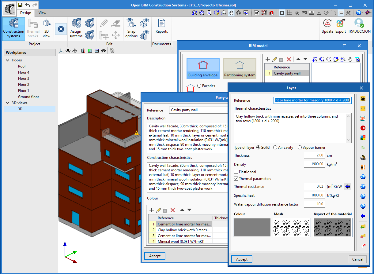
Export the definition of the construction solutions for thermal and sound analysis applications
As of the 2021.b version, Open BIM Construction Systems exports the definition of the construction solutions, together with their link to the elements of the architectural BIM model, to the BIMserver.center project. This information can be interpreted by the different specialist BIM tools aimed at the thermal and acoustic analysis of the building.
In the event that there is an association of construction solutions in the BIM project, which has been carried out using Open BIM Construction Systems, it will be used for the library of thermal or acoustic simulation programs instead of the types defined in the physical or analytical model. It should be noted that the layers that make up the system and their physical properties will be read, but they will not be modified when the BIM project is updated. This way, user changes are maintained within the specialist application, as well as the types that may be stored in ".bibgen" files.
Below are the current applications that are capable of reading and incorporating the construction systems of Open BIM Construction Systems in their design model:
- Thermal simulation
- CYPETHERM HE Plus
- CYPETHERM EPlus
- CYPETHERM LOADS
- CYPETHERM RT2012
- CYPETHERM RT2012 CNOA
- CYPETHERM REH
- CYPETHERM RECS Plus
- CYPETHERM C.E.
- CYPETHERM COMETH
- CYPETHERM RTExistant
- Acoustic simulation
- CYPESOUND
- CYPESOUND CTE
CYPECAD
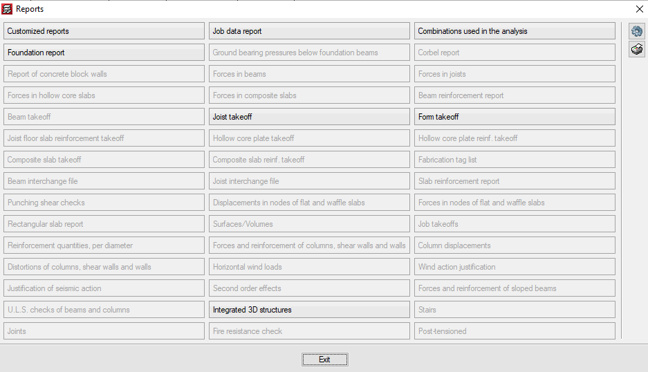
Project reports
In the 2021.b version, the "Reports" dialogue of the "File" menu can be configured by users. The appearance of the panel that is displayed when "Reports" is pressed has changed. It shows all the reports that are available in the program. The buttons that correspond to reports that cannot be displayed in the current project are disabled.
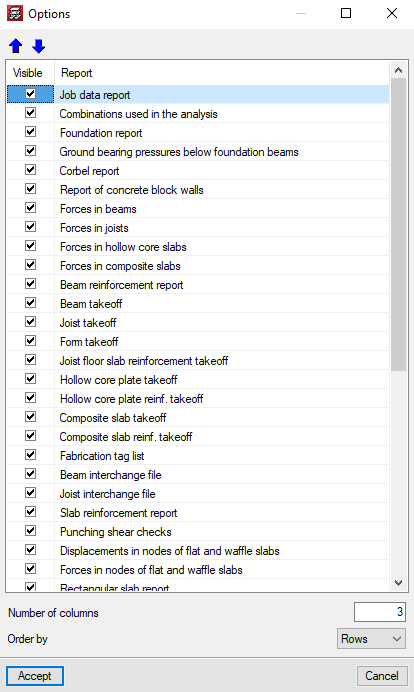
The "Options" button allows users to select which reports appear in the panel and the order in which they are displayed. This way, users can only show the reports that they usually use in the panel organised in accordance to their preference criteria.
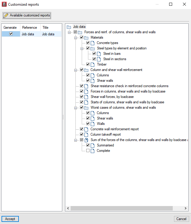
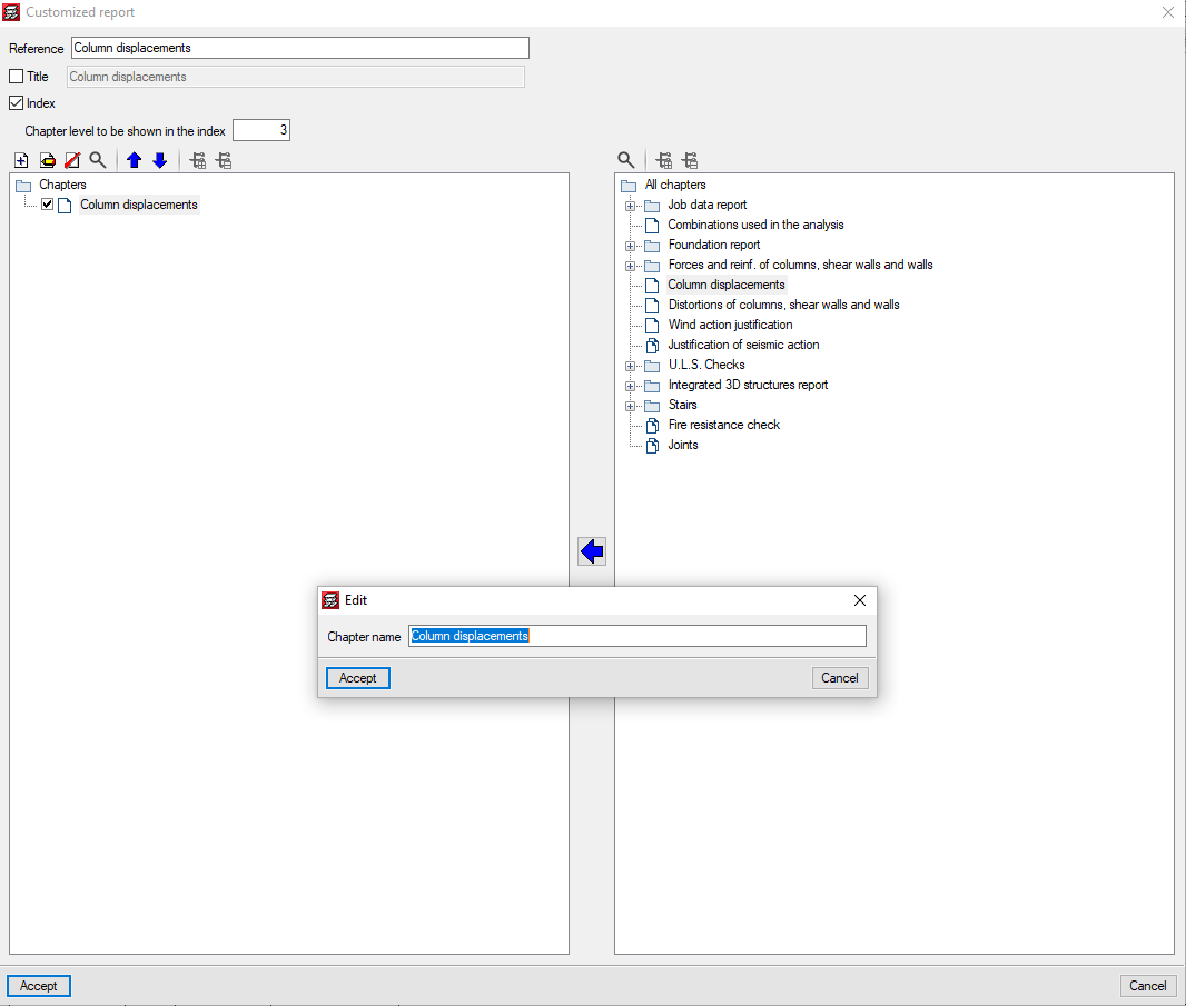
Customised reports
As of the 2021.b version, users can customise CYPECAD reports.
The "Customised reports" option allows users to select the reports that are to be generated. These reports must have been defined previously using the "Available customised reports" button.
These reports can be used in any project and can be used on another computer on which the 2021.b or later version is installed.
For customised reports, users can define their chapters as well as the title of the reports and whether their index and chapter levels are to appear.
The chapters that make up the report must be selected based on the chapters of the predefined reports that appear in the tree on the right. They can be grouped and organised as users wish. The name of the chapters can be modified, and users can add empty chapters to include the information later on.
For the time being, the chapters of 13 predefined reports can be used, but we continue to work to implement as many predefined reports as possible.
Other improvements and corrections
The 2021.b version of CYPECAD includes other improvements and program corrections that may be required in unique cases:
- The "Characteristics that have been considered for the soil-structure interaction" have been improved. Now, all the information is contained in a single table.
- The soil-structure interaction can be edited when editing footings and pile caps.
- Object snaps no longer have to be activated in the Frame reinforcement editor to consult checks.
- A waffle slab reinforcement error has been corrected. On some occasions, the end of the anchorage of the second layer reinforcement was straight when it should have been curved.
- The "Tags" option is added to the "Results" tab. Until now, it was only available in "Beam Definition".
- The size of the “Block frame reinforcement” dialogue box can be adjusted.
- In the "Column schedule" drawing, the text of the floor size is not limited.
- "Assign wall foundations" is included in the "Foundation" > "Foundation elements" option in the "Results" tab.
- A specific error that occurred when structures with connections were exported to an IFC file has been corrected.
- Specific errors that arose when consulting contour maps, causing a general error in the program, have been corrected.
- A warning is displayed if the top of a wall is defined with several sloped planes. Previously, this case produced a general error in the analysis process.
- Some of the thickness values of anchorage plates, which were displayed rounded, are now displayed with greater precision in drawings.
- The criteria to determine the depth of beams that are embedded in walls and crown beams has been modified. If the beam is in contact with a floor slab, its depth will be taken as the largest value between the depth of the floor slab and the value defined in the options. Otherwise, it will be taken as the greater value between the wall thickness and the value defined in the options, with a maximum limit of one metre.
CYPE 3D
Improvements and corrections
The 2021.b version of CYPE 3D includes the following improvements and corrections:
- In the scale of the contour map values, the dark colours of the background did not allow for some values to be viewed clearly. Now, all values can be read perfectly.
- Some of the thickness values of anchorage plates, which were displayed rounded, are now displayed with greater precision in drawings.
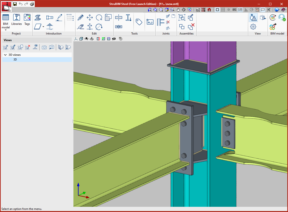
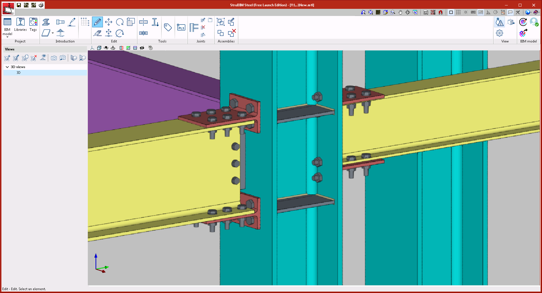
StruBIM Steel
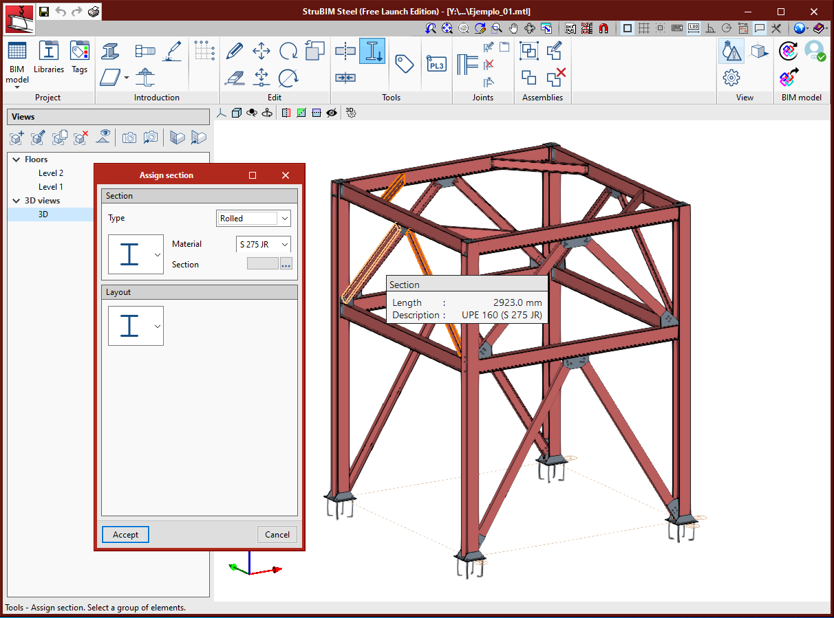
Assign section
A tool has been implemented to assign the type of section to a selection of bars.
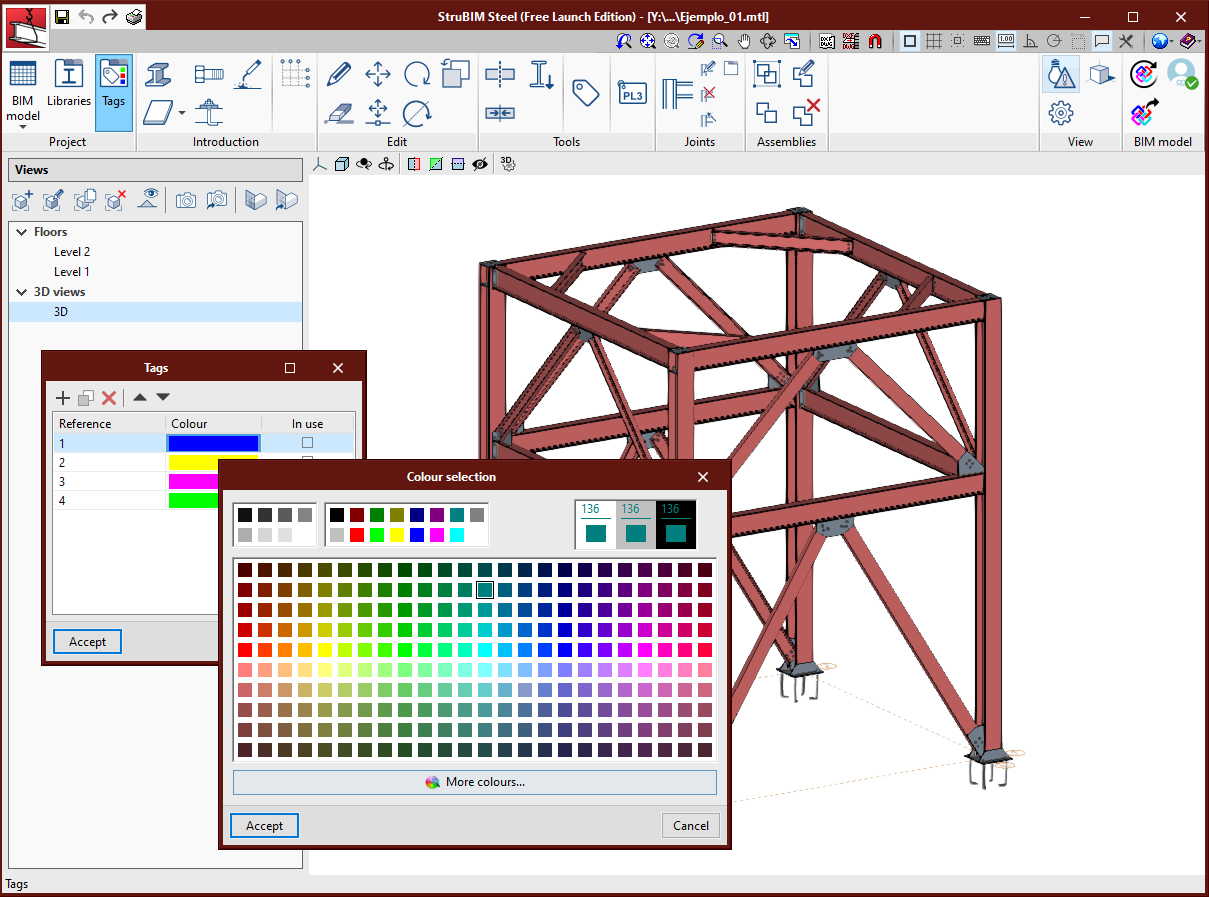
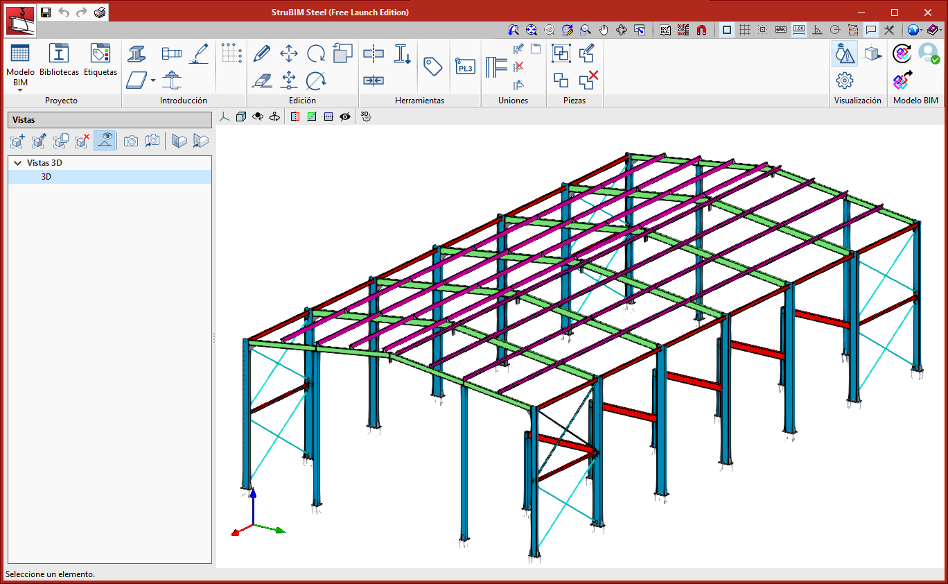
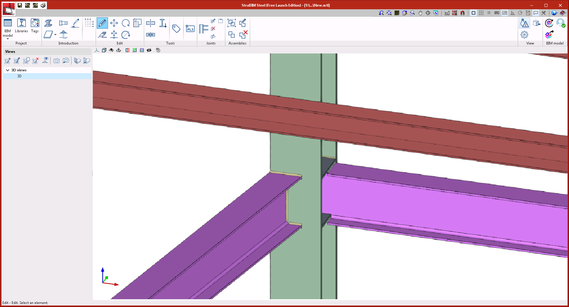
Assign colours by tag
Within the tags manager, each tag now has an associated colour. Elements will be represented in the 3D view, in the colour of the assigned tag. When an element has several tags assigned to it, it is represented in the colour that has been assigned to the first tag, in accordance with the order that has been established in the tags manager.
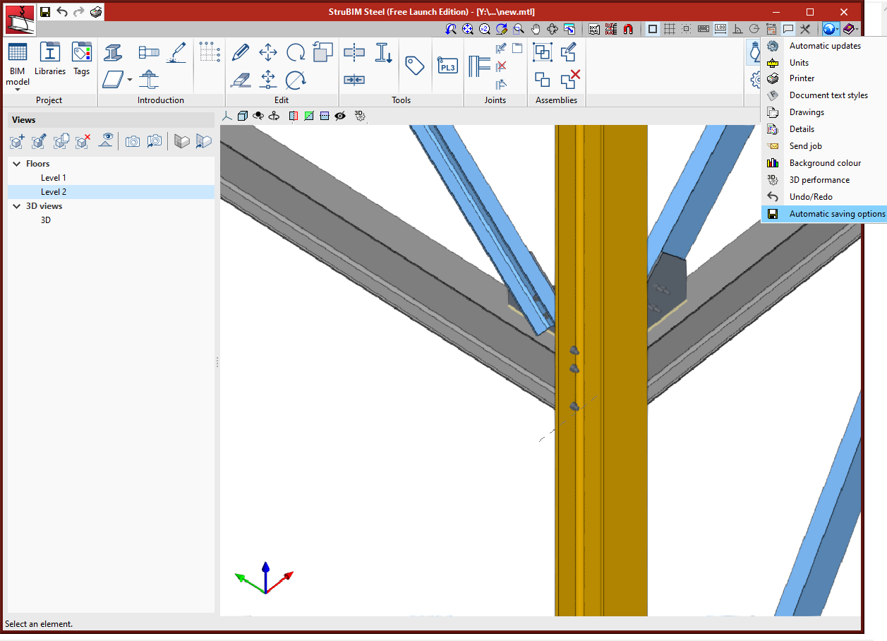
Automatic saving options
Within the "Configuration" menu, "Automatic saving options" has been added. Using these options, users can configure when the work will be saved automatically.
Multiple execution of the program
As of the 2021.b version, several program instances can be opened simultaneously.
Export the 3D view of the elements to the BIM model
A glTF that contains the elements that make up the structure can now be exported.
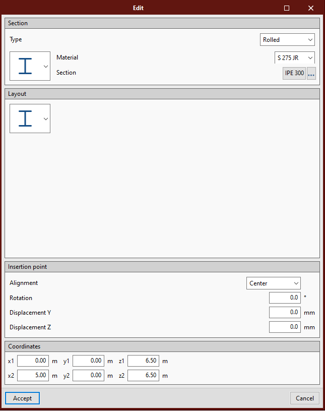
Edit section coordinates
The "Coordinates" section has been added in the edit sections dialogue box where users can consult and edit the coordinates of the initial and end points of the sections.
Improvements in existing connections
The following joints: "Moment connection to the flange of the main section" and "Moment connection to the web of the main section" have been improved. As of the 2021.b version, the webs can be displaced and the beams can reach the column obliquely in the horizontal plane.
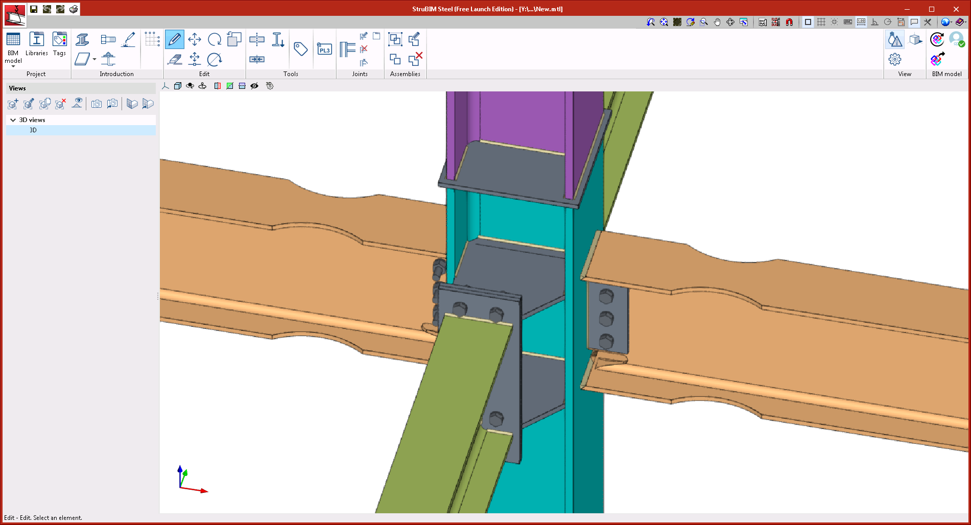
New types of connections
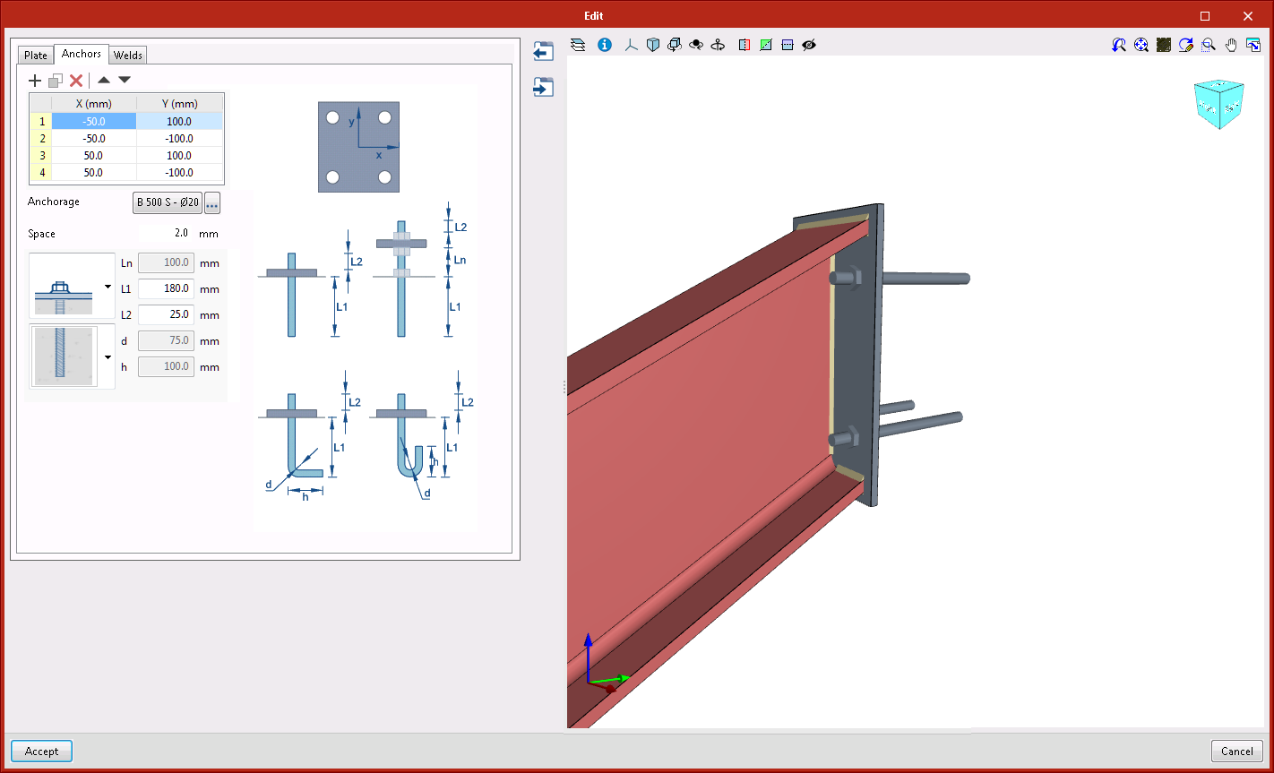
Anchorage plate to vertical surface
This connection is applicable to I-sections or rectangular hollow sections. A vertically-oriented anchorage plate is generated at the selected end.
Moment connection with reduced beam section
Beam to column moment connection, both with I-sections. With this connection, users can define trims in the flanges of the beam. Flanges are welded with single bevel butt welds, to do so, holes are also generated in the web of the beam, so they can be accessed more easily to perform the welds. The web can be connected using welds or bolted using a lateral plate.
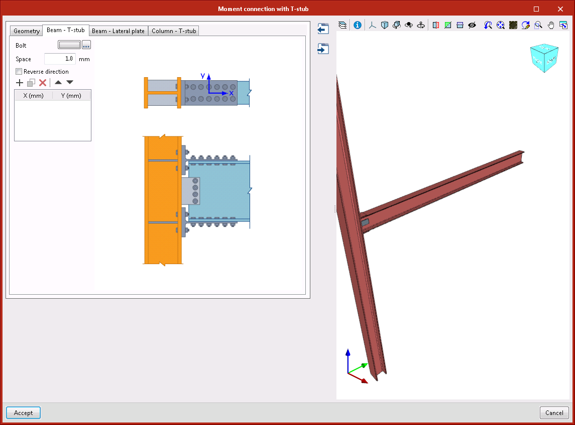
Moment connection with double T-stub
Beam to column moment connection, both with I-sections. The flanges of the beam are connected to the column using bolted rolled steel T-stubs. The web of the beam is connected using a bolted lateral plate.
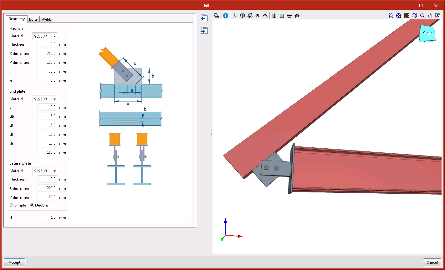
Diagonal connected to the main section, with end plate
This connection can be applied to a main bar consisting of an I-section, basic U-section, rectangular hollow section, or a diagonal bar consisting of an I-section, rectangular hollow section or circular hollow section.
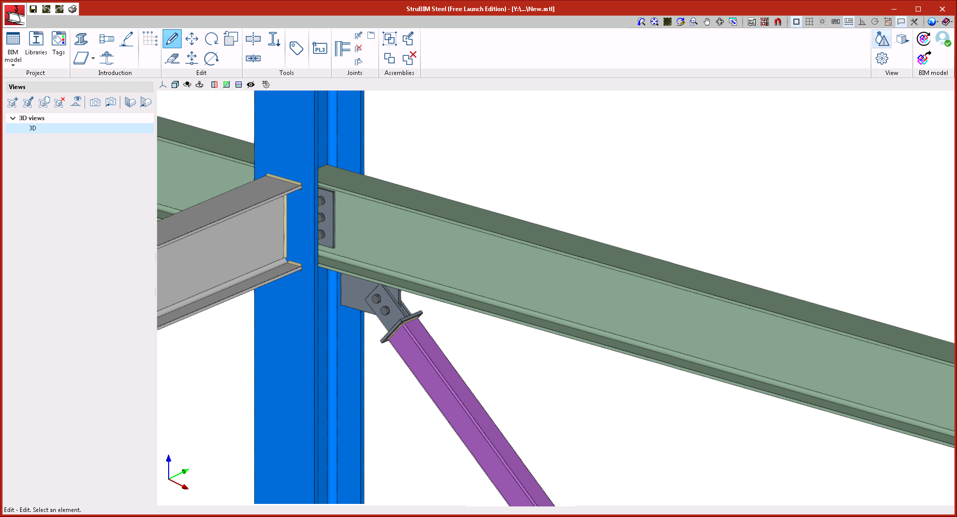
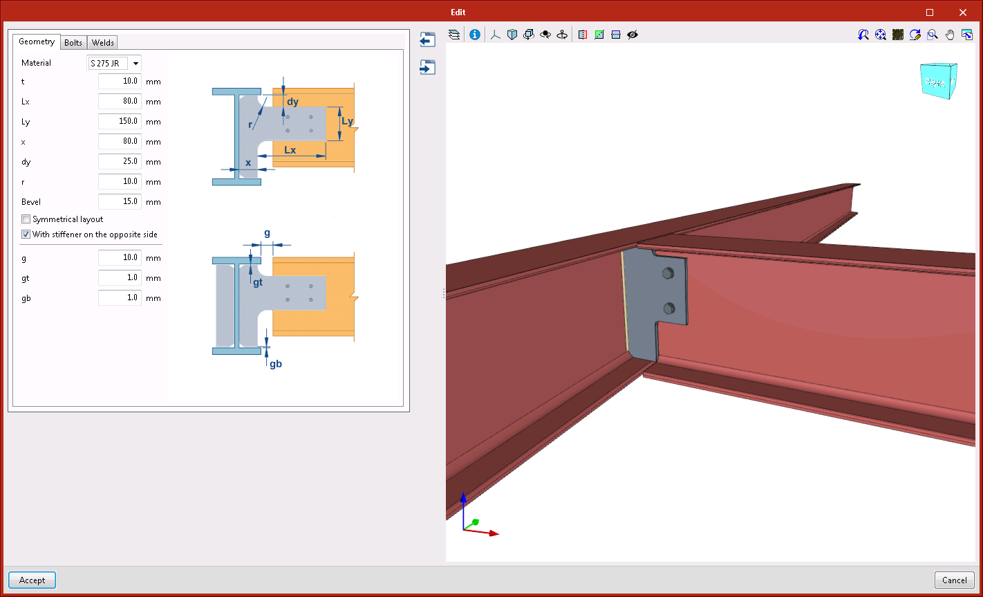
Beam connected to the web stiffener of the main section
This connection can be applied to a main I-section beam or secondary I-section beam. The secondary beam does not have to reach the main beam perpendicularly. Users can also add a stiffener on the opposite side.
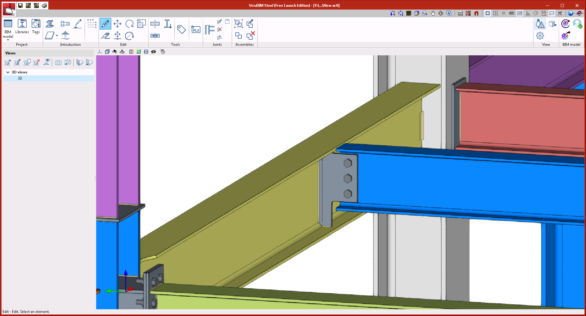
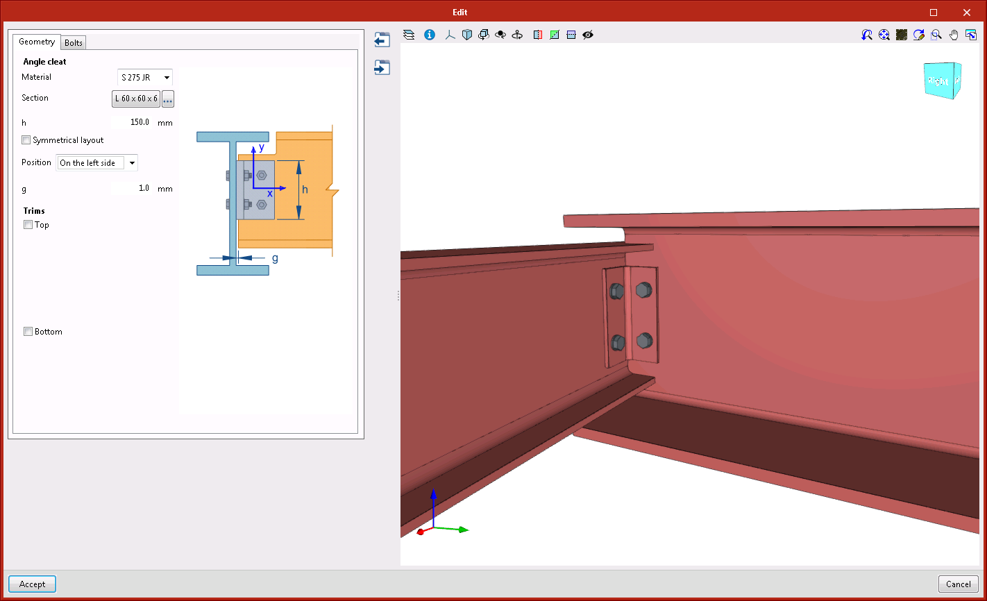
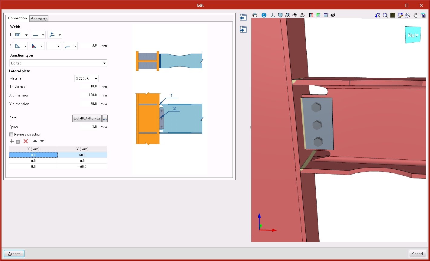
Beam connected with angle flange cleats to the web of the main beam
This connection can be applied to a main beam or secondary beam with I-sections or U-sections. The secondary beam must be perpendicular to the main beam since the connection is carried out using angle flange cleats with a length that is defined by users.
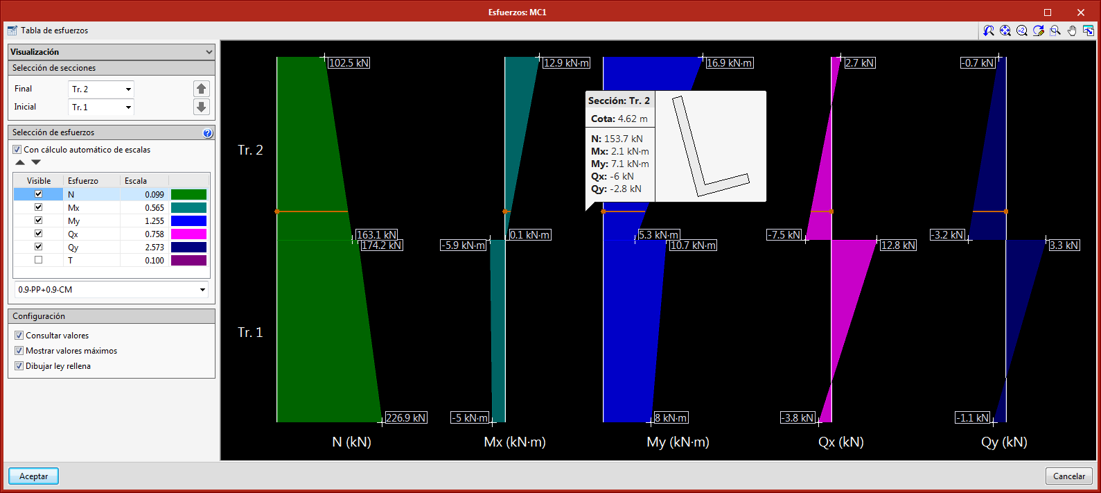
StruBIM Shear Walls
New panel for graphical representation of forces
New panel in which forces are represented graphically. When the "Forces" button is pressed, users access a panel that displays the combination force envelopes of the selected wall.
Optimisation in the analysis process
The analysis process has been optimised to obtain intermediate results and so speed up the on-screen view when the section of the wall is changed. This optimisation is most noticeable when the number of combinations is higher.
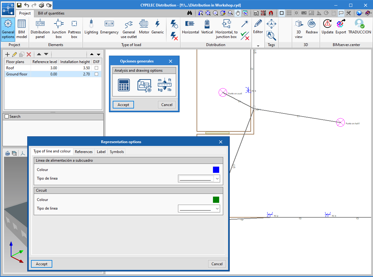
CYPELEC Distribution
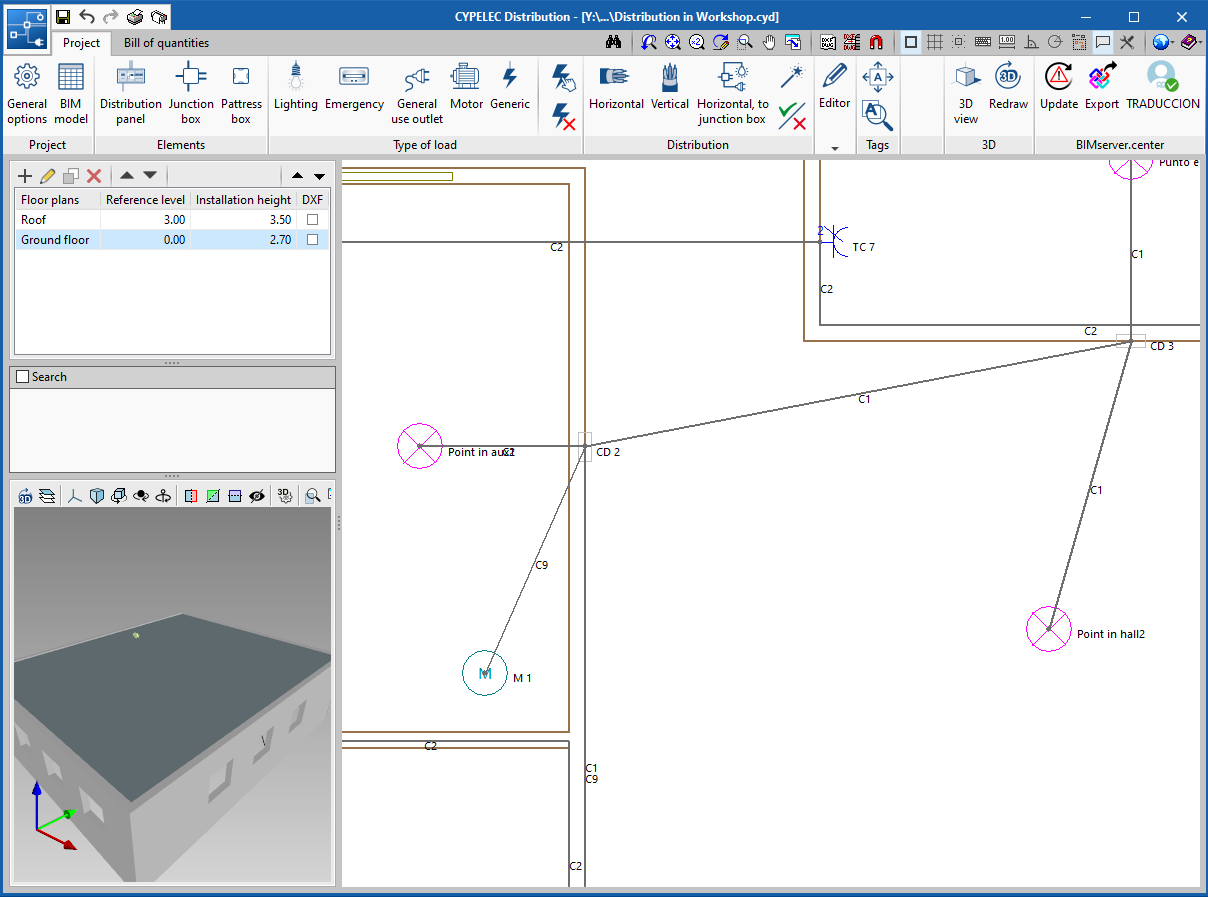
Representation options
New functionalities have been added to represent the types of lines and tags in spans and elements.
The "Representation options" icon has been added in "General options", which includes four tabs:
- Type of line and colour (new functionality). Allows users to select the colour and type of line to represent the supply lines to the subpanel and indoor circuits.
- References. Allows users to assign the default reference for the different elements.
- Tag (new functionality). Allows users to select, for each element, the properties that are to be represented on-screen and later on the floor plans.
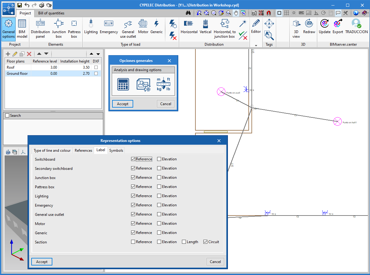
- Symbols. Allows users to edit customised symbols, which can then be assigned to different elements.
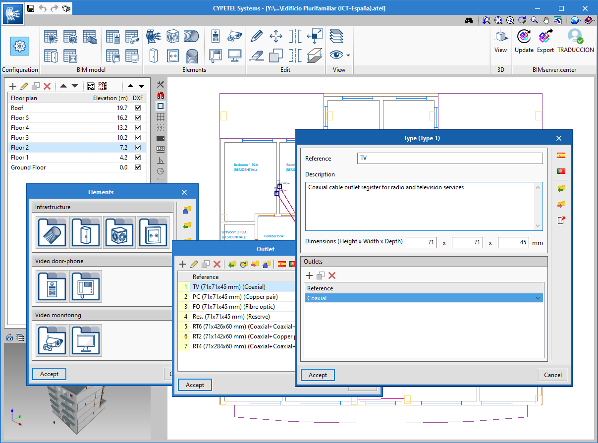
CYPETEL Systems and FAAST IT
Restructuring of the libraries and General options
The distribution of the toolbar has been modified and the equipment library has been placed in "General options".
CYPETEL Schematics, CYPETEL Systems and FAAST IT
Specific coaxial connectors for S/MATV and CATV
To distinguish between coaxial networks, two connectors have been added: "Coaxial S/MATV" and "Coaxial CATV".
Tool to export and import "General options" configuration
A tool has been implemented to import and export the "General options" configuration so it can be used in different projects.
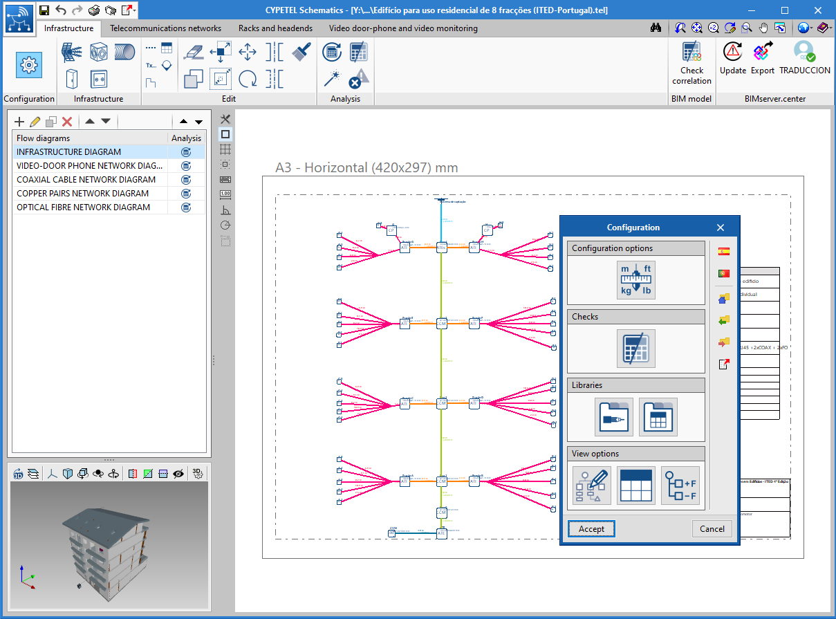
Configure "General options" by design code
Until now, only predetermined configurations were available for infrastructure elements and checks. Now, the program has complete configurations so users may define the "General options" of the project. For each design code, the program has a configuration in which the type of equipment, view preferences, checks, tables, units, etc. can be found, saving users a lot of time when preparing the project.
FAAST IT, CYPETEL Project ITED-ITUR, CYPETEL Wireless
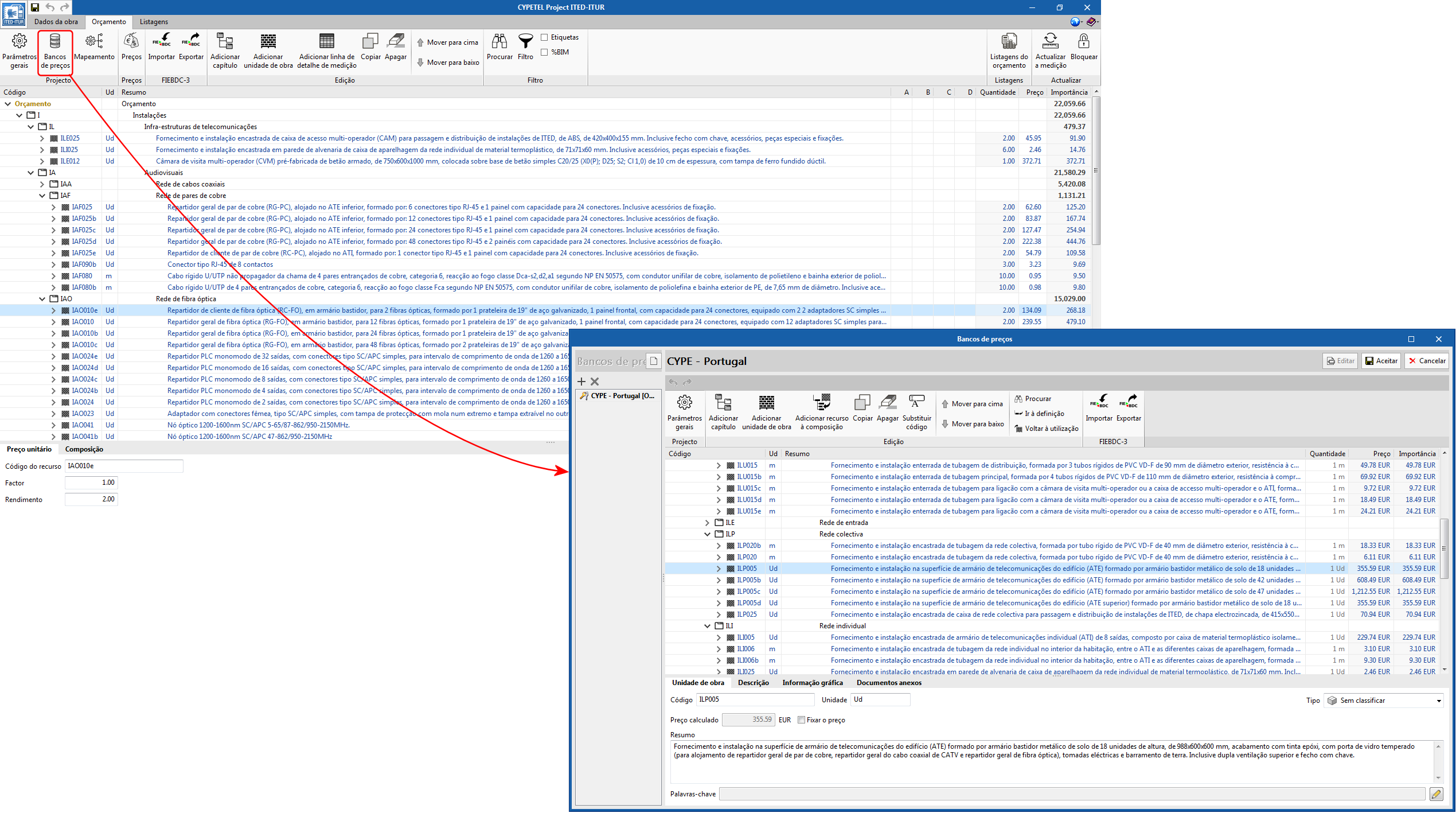
Bill of quantities tab
The "Bill of quantities" tab has been included. Now, users have tools to generate and manage the bill of quantities of the elements that have been entered.
More information in the "Bill of quantities tab" in project phase Open BIM applications.
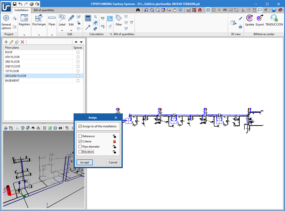
CYPEPLUMBING Sanitary Systems and CYPEPLUMBING Water Systems
New tools to manage blocked parameters
New tools have been included to manage blocked parameters.
Users can block the main parameters calculated by the program either globally or partially.
A tool has also been implemented to display the elements of the installation that have blocks activated.
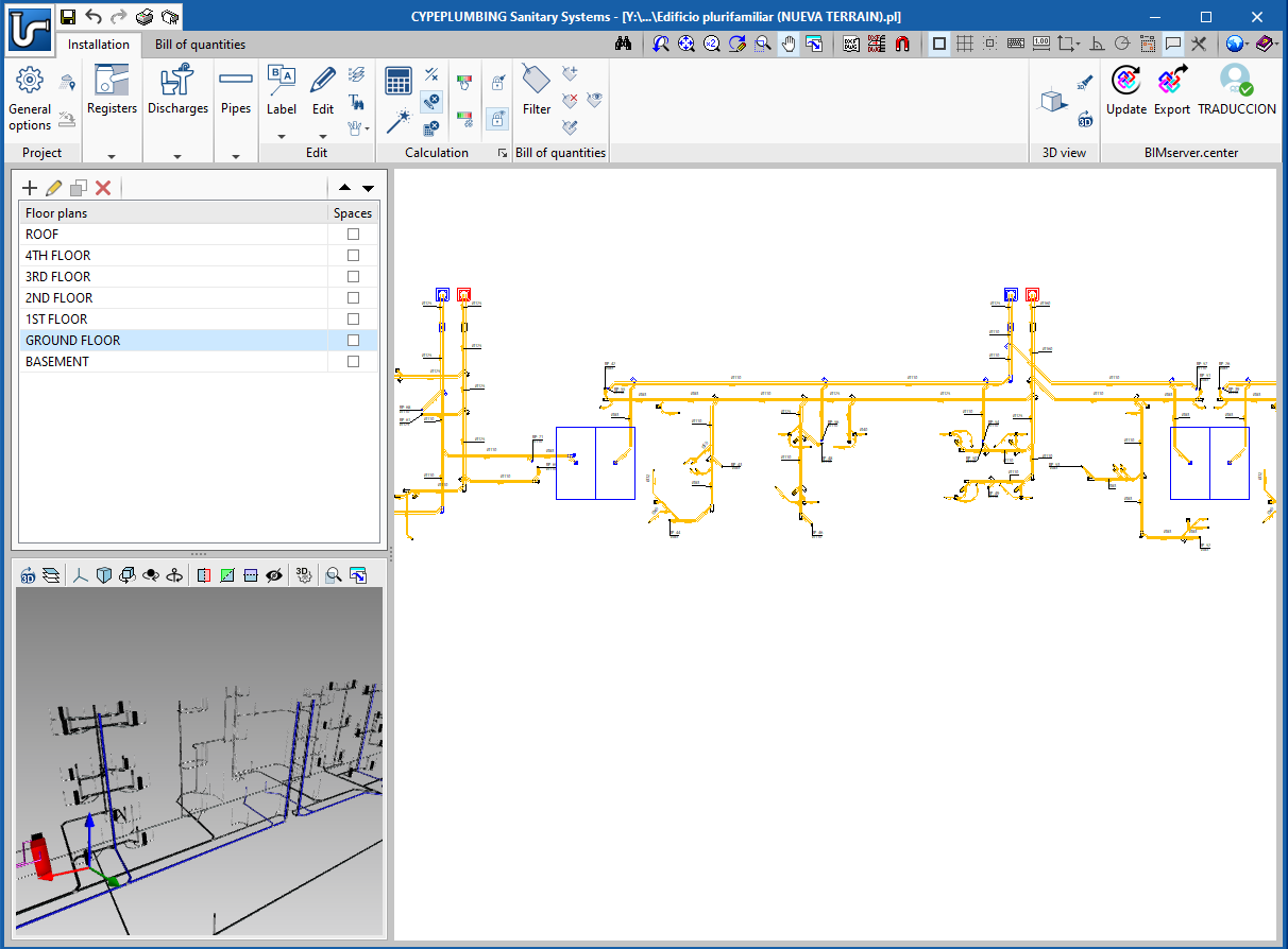
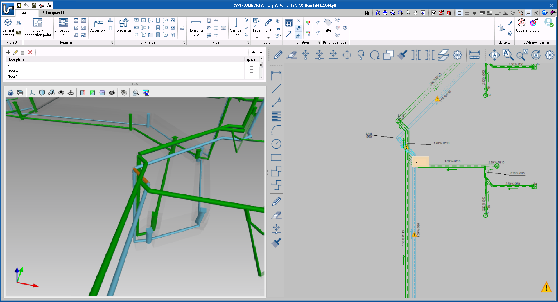
CYPEPLUMBING Sanitary Systems
Clash detection of wastewater pipes
As of the 2021.b version, CYPELUMBING Sanitary Systems detects if there are any clashes between pipes of the different networks that have been included in the program.
New aliaxis Phonoblack soundproof pipes catalogue
The 2021.b version of CYPEPLUMBING Sanitary Systems includes the Phonoblack soundproof pipes catalogue from the manufacturer aliaxis.
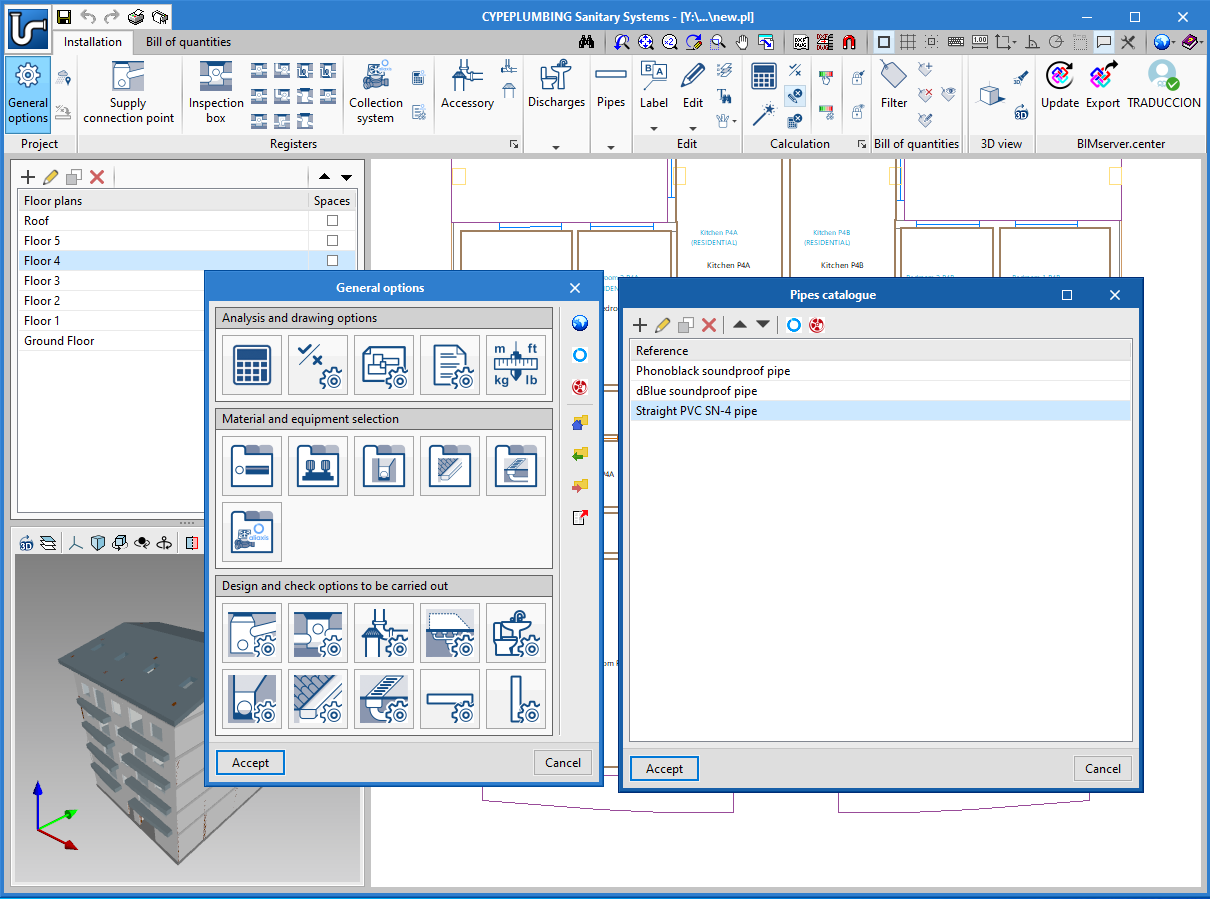
Addition of design criteria of the manufacturer aliaxis
As well as the addition of the aliaxis "Phonoblack" pipes catalogue, the design criteria for their pipes have also been implemented.
CYPEPLUMBING Water Systems
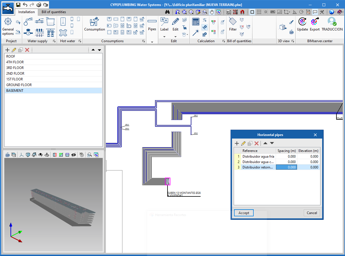
Simultaneous pipe entry
As of the 2021.b version, CYPEPLUMBING Water Systems allows users to enter several horizontal pipes that follow the same path. This tool also allows for them to be defined on several floors simultaneously.
CYPEHVAC Ductwork
Optimization of the analysis process
In the 2021.b version of CYPEHVAC Ductwork, the analysis process of the duct installations has been optimised, and is now faster. This is particularly interesting for large projects.
Open BIM Quantities and Elodie by CYPE
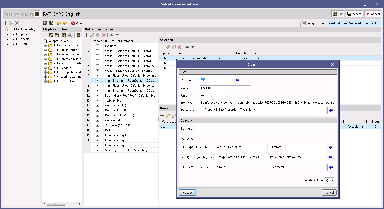
IFC entity properties
As of the 2021.b version, the properties of an IFC entity (IfcPropertySet) can be used in the "Set of measurement rules" of the project to generate the quantity take-off (variables B, C and D), as was already done previously with the quantities (IfcQuantitySet). The reason for this implementation is due to the existence of BIM modellers that are based on the IFC standard, which export quantity-orientated attribute groups as properties (IfcPorpertySet), instead of quantities (IfcQuantitySet). Now, in the job or project units panel of a "Measurement rule", users must indicate the type of attribute that is to be assigned to each variable, similar to what must be done when selecting the entities of the BIM model.
Arquimedes and Job control
Bill of quantities of Revit models
Use the same quantity extraction combination for entity links of the same family
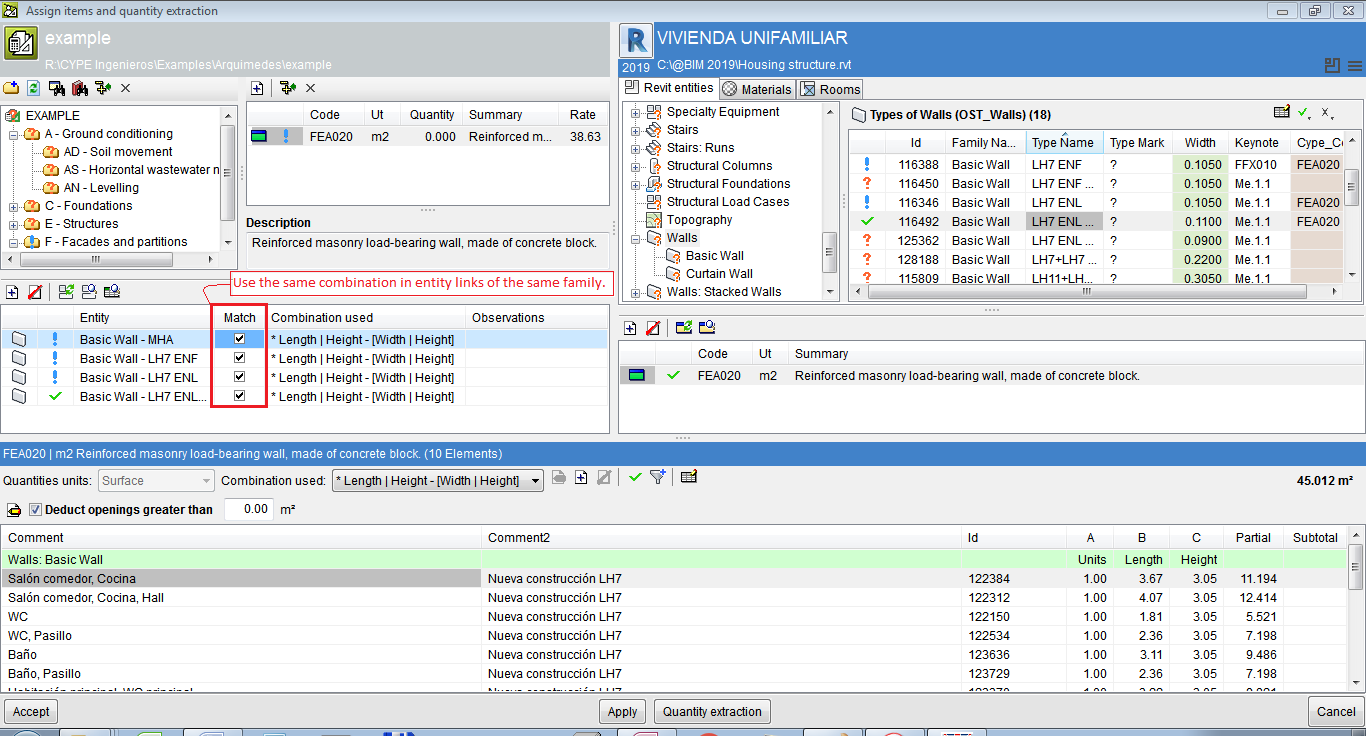
When, from the "Assign job items and quantity extraction" dialogue box, there is more than one link of several Types of the same Family to the same job item, the Match column allows users to use the same combination in entity links of the same family.
It is possible to match the sets of measurement rules of several entity links with a job item. When one of them is modified, the modification is applied to all the links of that job item. If the project already had different rules (quantity combinations) in the same job item, the program does not unify them; it only does so if one is modified.
All entities (Types) that are linked to a job item will have the same set of measurement rules because they refer to the same job item.
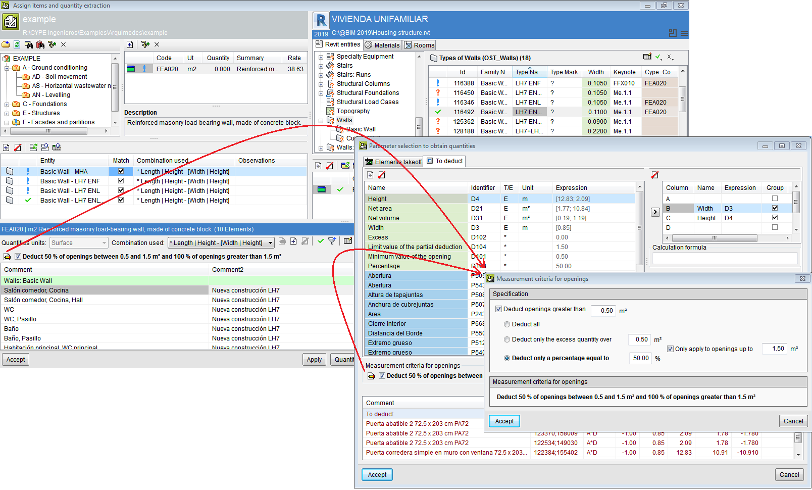
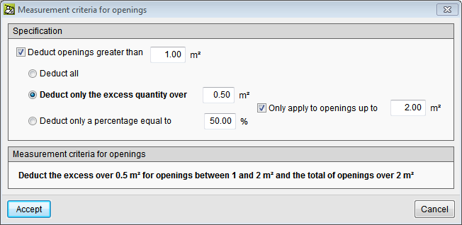
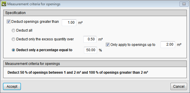
Sets of measurement rules for openings
More options have been included within the "Deduct openings greater than" option to take into account more measurement rules, e.g. the possibility to deduct only one part (usually 50%) of openings that are smaller than a given value, and deduct them all if they exceed that value. The set of measurement rules for openings can be accessed using the "Set of measurement rules for openings" button. Here, users can:
- Deduct all openings that are greater than a given surface area.
- Only deduct the excess of a given surface area of openings, including deducting the excess of a given surface between two values and the total surface area of openings that is greater than a given surface area.
- Deduct a given percentage of the openings, or just deduct a given percentage of a surface area that lies between two given values and 100% of the openings of more than one given surface area.
Import quantities from "ArchiCAD® 24 SPA"
The connection between Arquimedes and ArchiCAD® has been updated in the 2021.b version, to adapt it to import ArchiCAD® quantities from its new version, "ArchiCAD® 24 SPA". The connection with ArchiCAD® is a tool of the "Automatic quantity import from drawings and link with CAD programs" module.
Return to the 2021 version download area
Tel. USA (+1) 202 569 8902 // UK (+44) 20 3608 1448 // Spain (+34) 965 922 550 - Fax (+34) 965 124 950