NEW FEATURES OF “Open BIM Systems”
NEW PROGRAMS
NEW FEATURES OF EXISTING PROGRAMS
- Improvements common to all programs
- Code implementation and improvements in its application
- IFC Builder
- Open BIM Model Checker
- CYPECAD
- Timber columns (CYPECAD module)
- Options to import floor slab outlines from the BIM model
- Improvements in the column introduction and editing panel
- Options to manage beam alignment references
- Move texts, introduced in “Editing resources”, from the “Drawings editor” of the “Drawing composition”
- Wind load justification report for “NBR 6123” and “NF EN 1991-1-4/NA”
- CYPECAD and CYPE 3D
- StruBIM Design Shear Walls
- StruBIM Design Shear Walls and StruBIM Rebar
- CYPECAD MEP
- CYPETEL Schematics
- CYPETEL Systems
- CYPELEC PV Systems
- CYPETHERM programs with the EnergyPlus™ analysis motor (CYPETHERM EPlus and CYPETHERM RECS Plus)
- CYPETHERM programs with the EnergyPlus™ analysis motor and CYPETHERM LOADS
- CYPETHERM Eplus
- Return to the 2020 version download area
NEW FEATURES OF “Open BIM Systems”
EasyVMC (New program)
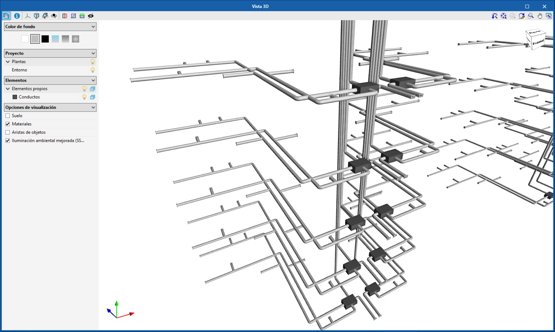
EasyVMC is a free application with which users can design controlled mechanical ventilation installations using ventilation systems from the manufacturer Soler&Palau (S&P), using an architectural model located on the BIMserver.center platform.
The program guides users along the design process of the ventilation ducts, obtains the load loss of the installation and connects to the S&P selection portal to obtain the most adequate ventilation equipment. Furthermore, EasyVMC sends the portal a list of the materials of the complete installation including the fans, spigots, ducts and accessories that are required for the correct operation and installation of the ventilation system. EasyVMC is integrated in the OpenBIM workflow using the IFC standard.
More information on EasyVMC (in Spanish).
Open BIM DAIKIN
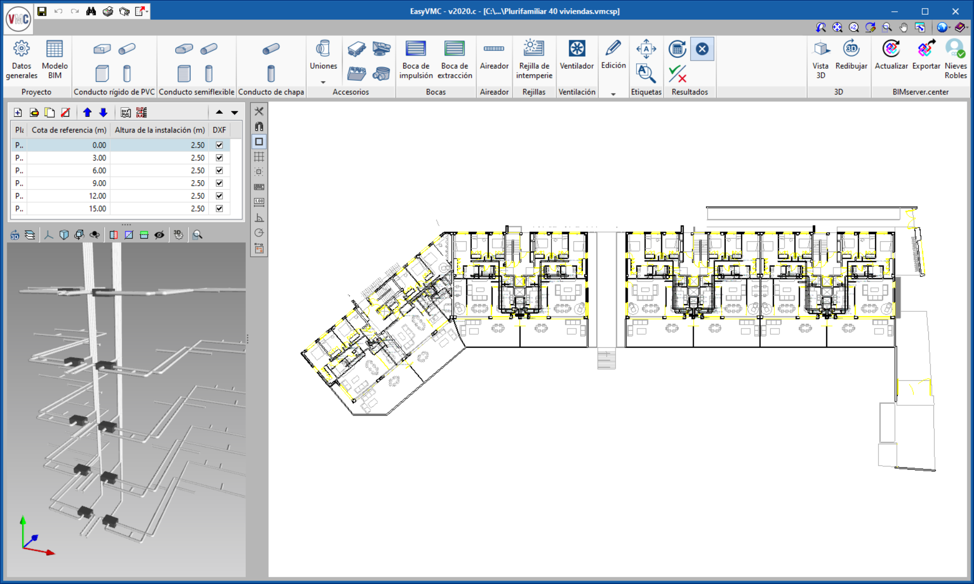
HYDROBOX indoor water production units
HYDROBOX water production units have been added. These are indoor units that can be connected to a VRV system, and are used to air condition spaces and for hot water production.
Open BIM Movair
New part: Branch with rectangular section
As of the 2020.c section, duct branches can be inserted in the design (New part > Branch with rectangular section > mark the spigot where the new part is to be placed). In the panel that opens, users can indicate the widths of the outlet and branch. The dimensions of the spigot are introduced automatically by the program.
Generate parts between two spigots
A new tool has been implemented as of the 2020.c version: Generate parts between two spigots. Using this tool, users can choose if the connection will be with an elbow or a branch.
The new tool is very easy to use and helps users to design the installation by providing solutions to the connections that are generated.
Open BIM RenoZEB – Focchi Facades
Corner panels
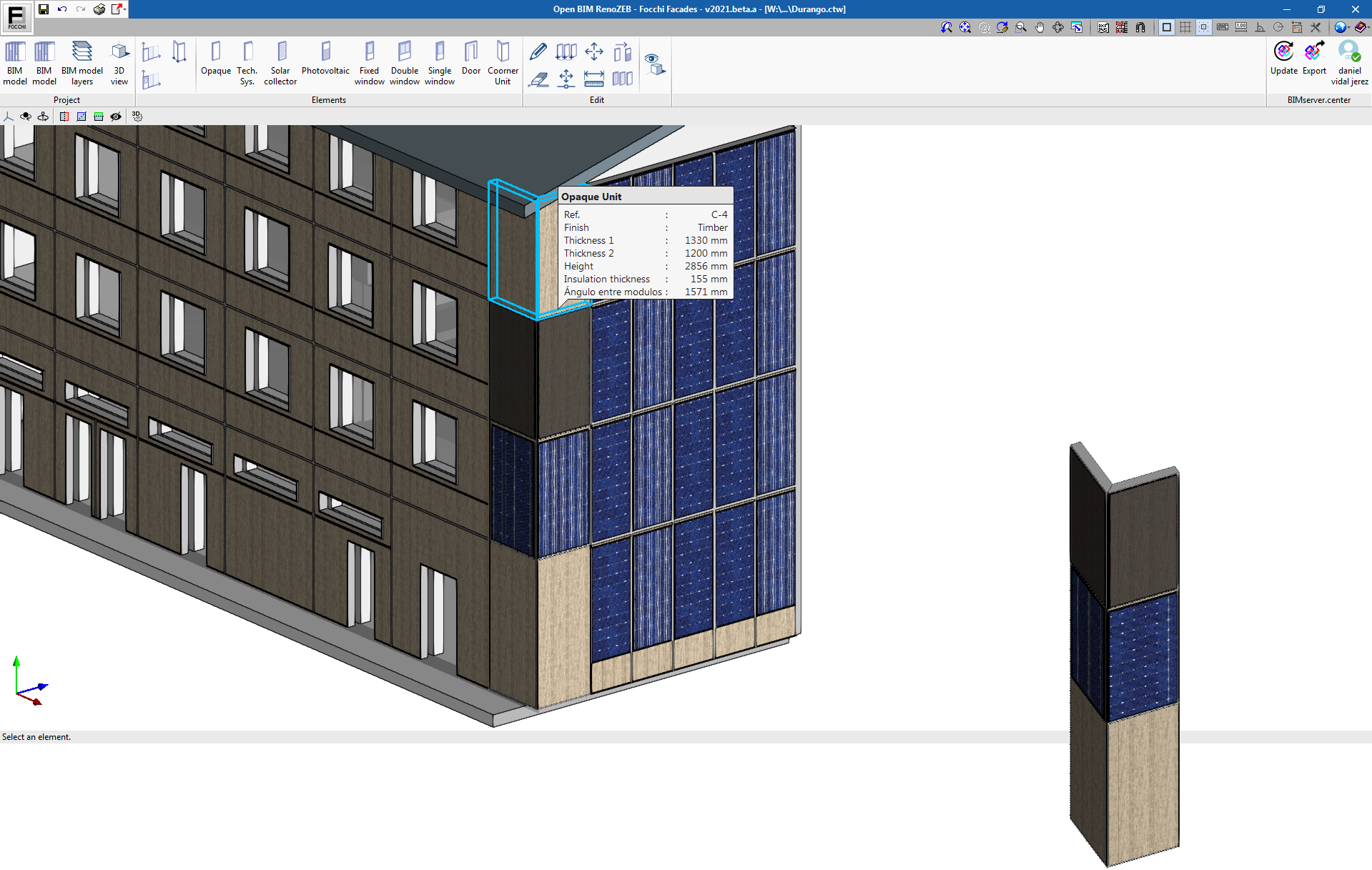
The 2020.c version of “Open BIM RenoZEB - Focchi Facades” includes the option to introduce “Corner panels”, this way a continuous envelope can be generated around the whole building. The corner panels can also consist of photovoltaic panels and solar collectors.
To generate a corner panel, click on the first point where the first panel begins, click on the second point to establish the corner and then the third point to indicate the end of the second panel.
Export quantities in FIEBDC-3 format
The program can export the quantities of the panels in FIEBDC-3 format, which can then be used in budget management programs.
New project example: Vorü - Estonia
The example consists of a residential building with terraced housing at its ends and apartments at its central nucleus. This building is part of the RenoZEB European project and will be renovated with Focchi panel systems, as well as its equivalent in Durango.
NEW PROGRAMS
Electrical installations
CYPELEC Distribution
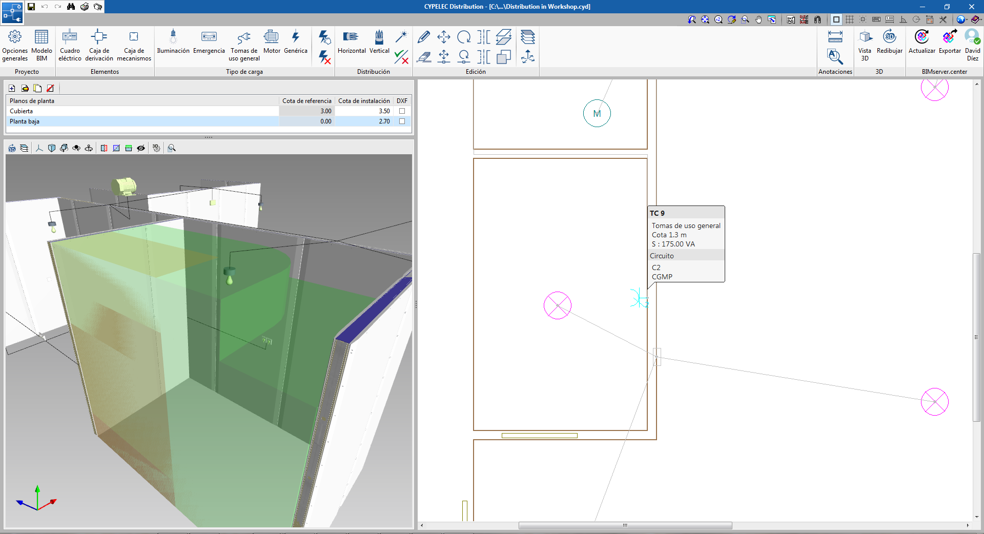
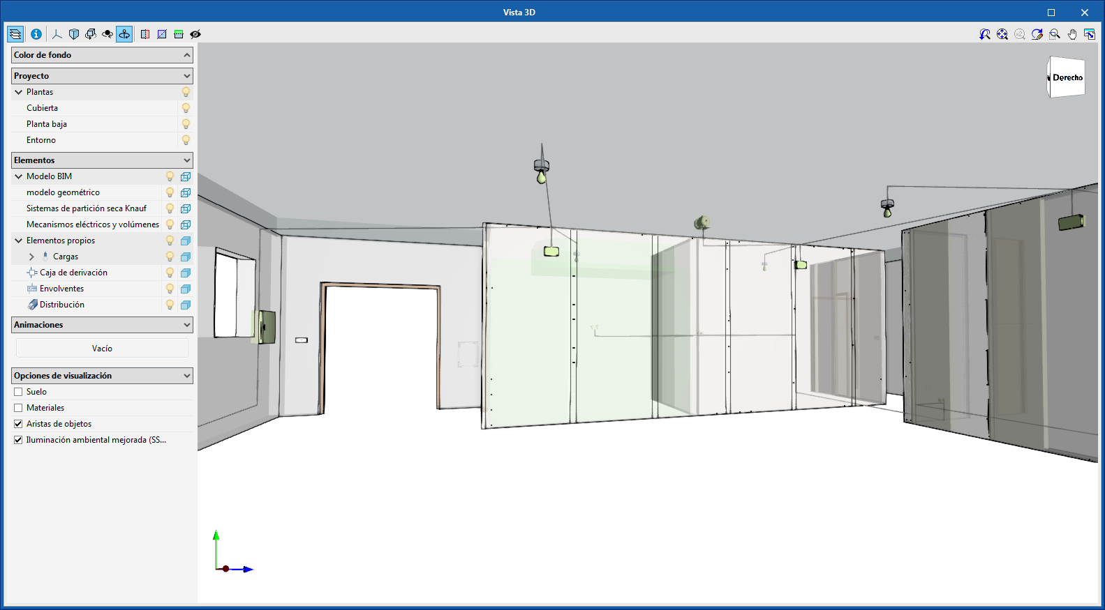
“CYPELEC Distribution" is a program with which users can obtain the 3D implementation of the circuit and load distributions for electrical installation projects. This application is integrated in the Open BIM workflow using the IFC standard.
"CYPELEC Distribution" imports the geometry of the BIM project building to which it is connected on the BIMserver.center platform. If the project also includes a BIM model with the arrangement of the electrical mechanisms of the installation (designed, for example, by the "CYPELEC Electrical Mechanisms" application), users can import it to define the indoor electrical distribution.
“CYPELEC Distribution" provides a table of the results, the electrical distribution drawings and 3D Model of the electrical distribution.
Using the Open BIM workflow, CYPELEC "Distribution" exports information on the distribution, which can then be interpreted by electrical installation programs (such as CYPELEC Core, CYPELEC REBT, CYPELEC NF and CYPELEC RETIE) and they automatically generate the single-line diagram.
More information on CYPELEC Distribution.
Telecommunications installations
FAAST IT
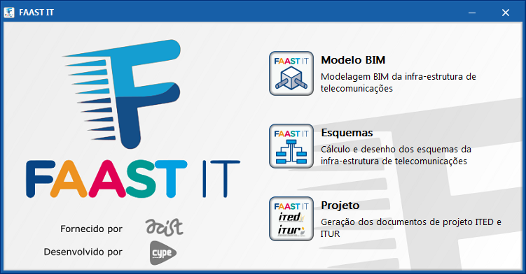
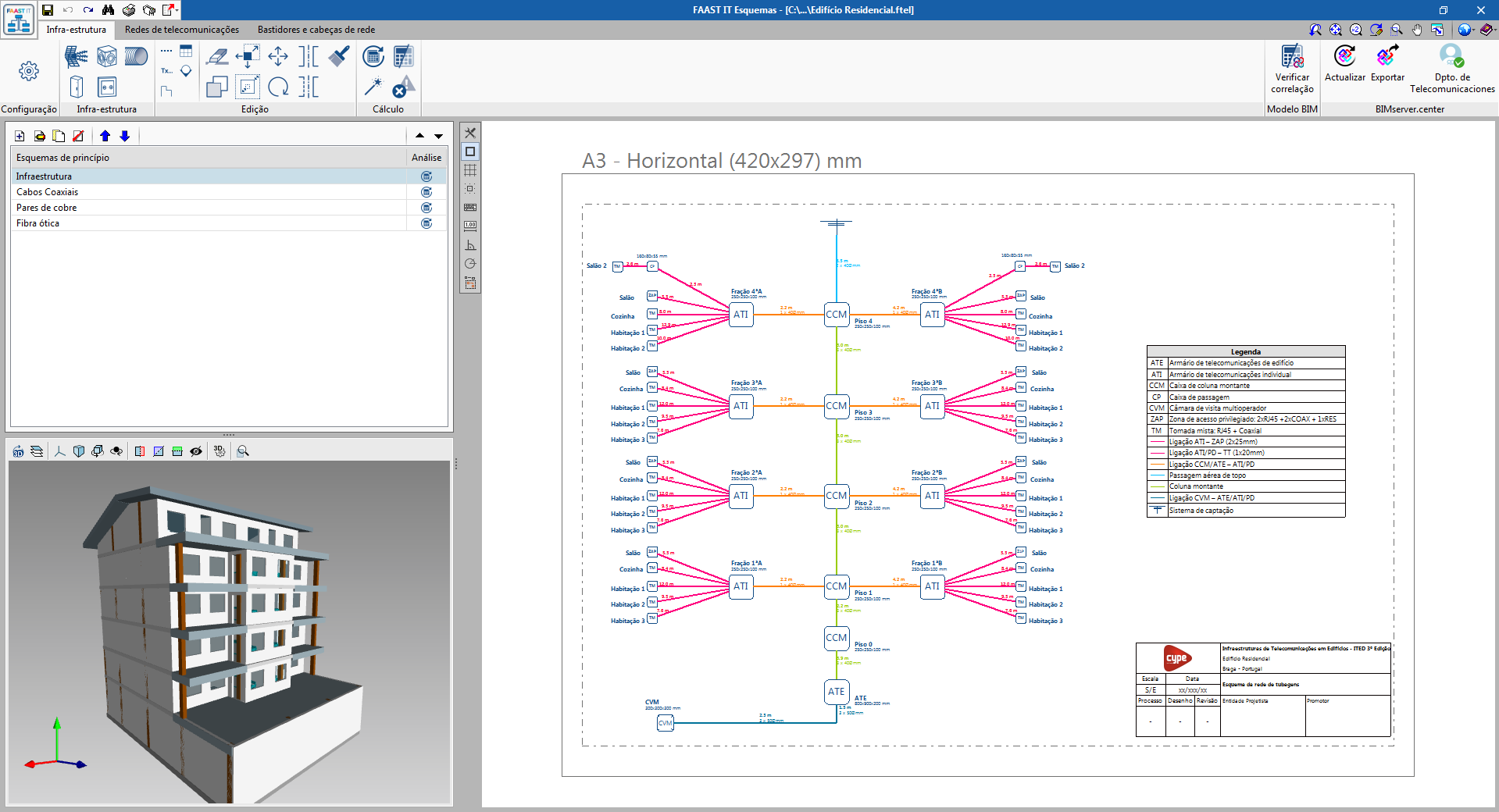
FAAST IT is a suite of programs to develop telecommunications infrastructure projects in Portugal, in accordance with the ITED Manual, third edition (Buildings) and the ITUR Manual, second edition (Urbanizations, plots and sets of buildings).
FAAST IT has been developed by CYPE Ingenieros S.A. to be distributed amongst associates of the Portuguese Business Communications Association (ACIST), free of charge and in Portuguese.
The three programs in the suite are integrated in the Open BIM workflow by exchanging standard IFC files. These are:
- BIM model
BIM modelling of the telecommunications infrastructure. - Diagrams
Analysis and design of the telecommunications infrastructure diagrams. - Project
Generation of the ITED and ITUR project reports.
More information on FAAST IT (in Portuguese).
NEW FEATURES OF EXISTING PROGRAMS
Improvements common to all programs
Import PDF files as drawing templates
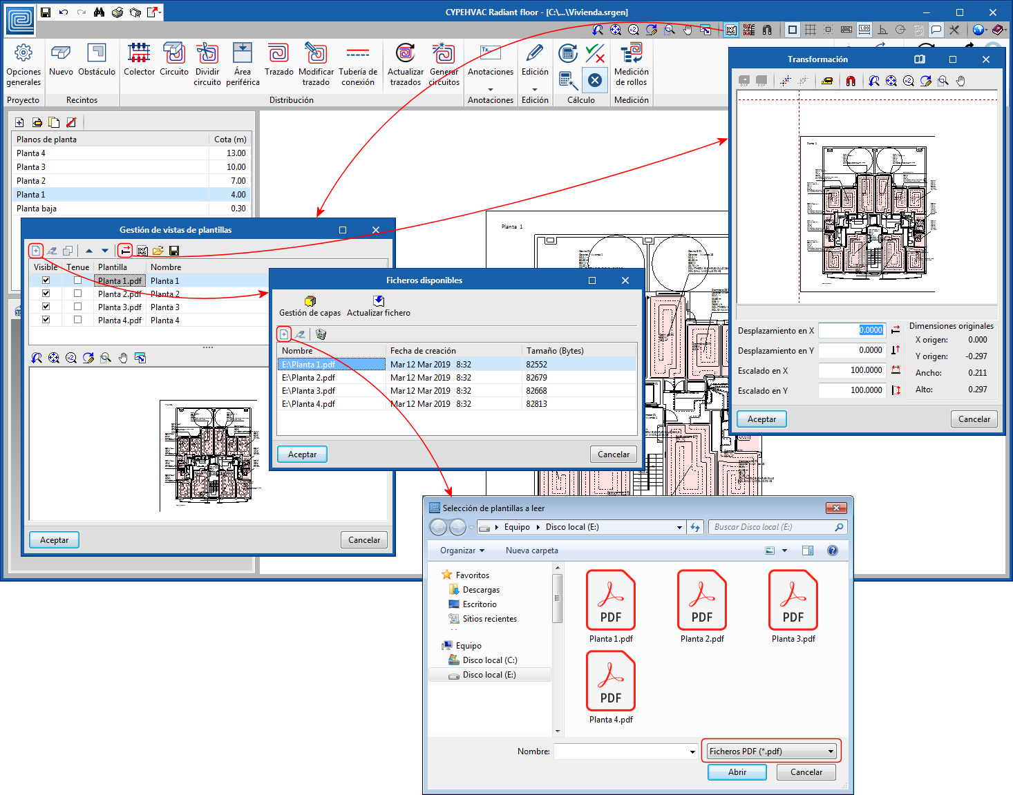
As of the 2020.c version, users can import files in PDF format in CYPE programs to use them as drawing templates.
This way, PDF files join DWG, DXF and the most common image format files as files that can be used as templates on each floor.
The programs that can currently use this feature are:
- CYPECAD MEP
- IFC Builder
- CYPEHVAC Radiant floor
- GIACOMINI, ORKLI, POLYTHERM, ROTH, SAUNIER DUVAL and UPNOR Open BIM Systems.
In upcoming versions, this feature will be implemented in other CYPE programs in which data is introduced by floor.
Rotate about the camera in 3D views
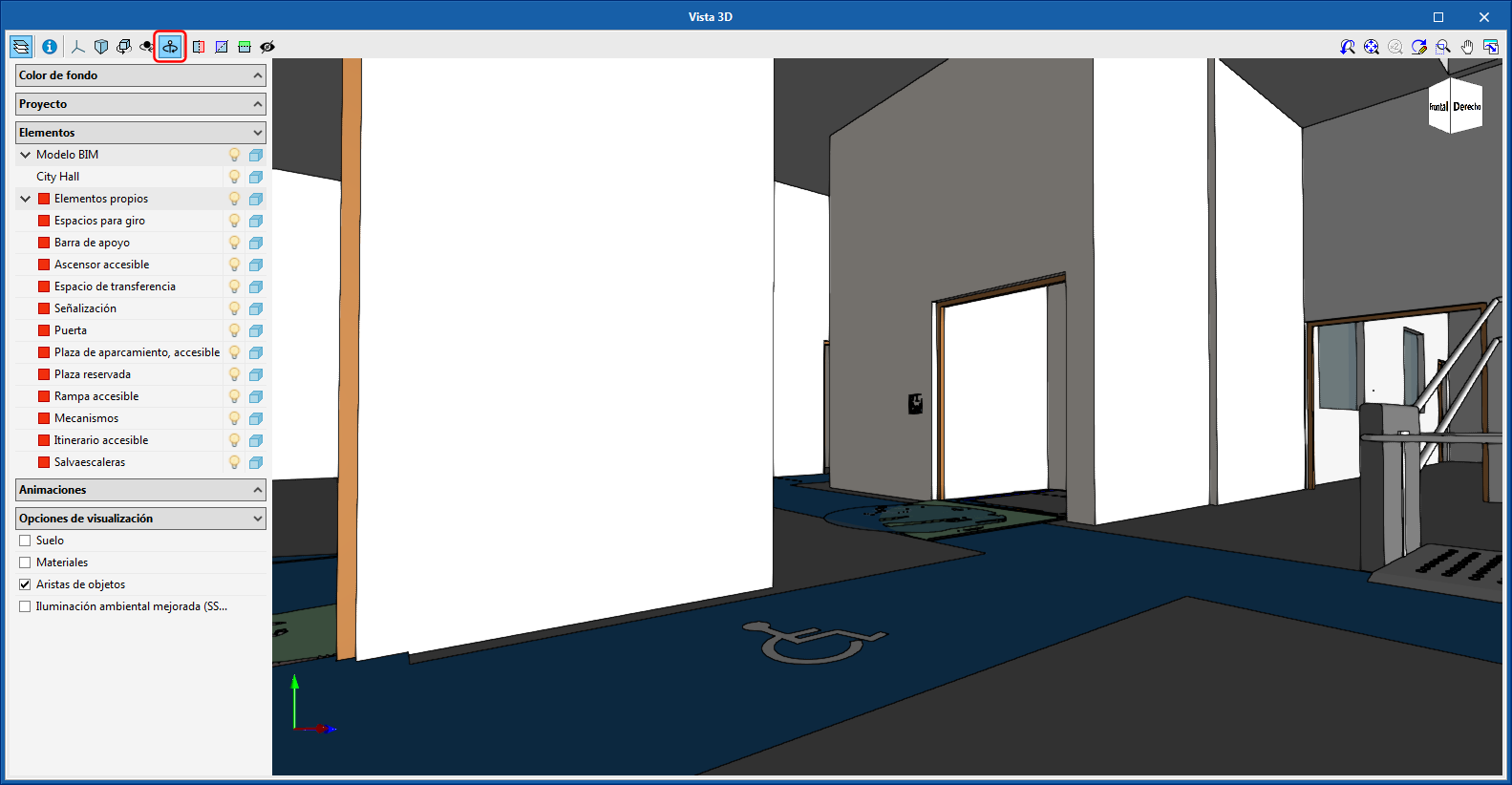
In the 3D view windows of all CYPE programs, a tool has been implemented that allows users to rotate the scene about the vertical axis of the camera.
With this tool (together with the zoom that can be carried out using the mouse scroll wheel towards a point where the cursor is located), users can move around in the 3D view of a building as if they were walking inside it.
Button to add the selected directory to the “Quick access” directories
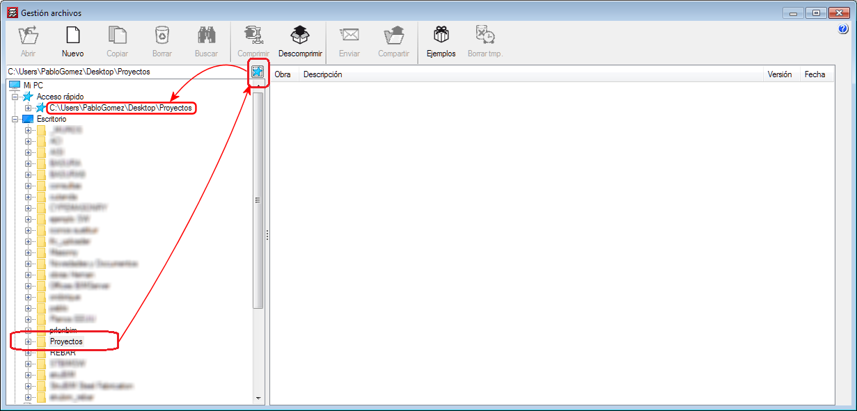
A tool has been implemented in the 2020.c version to add the selected directory to the “Quick access” directories.
Up until the 2020.b version, they could only be added manually, i.e. by writing the path of the directory or pasting the path having copied it from Windows Explorer.
Code implementation and improvements in its application
Loads on structures. Wind loads
Wind load justification report for “NBR 6123” and “NF EN 1991-1-4/NA”
The codes for which this justification report has been implemented can be consulted in the “Wind load justification report” section of the new features of CYPECAD on this webpage.
IFC Builder
Export quantities to the BIM project
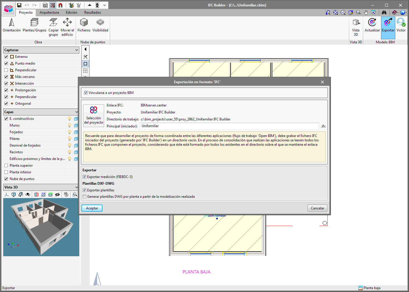
As of the 2020.c version, IFC Builder allows users to export the quantities of the project, in FIEBDC-3 (.bc3) format, to the linked BIM project on the BIMserver.center platform. This information is generated automatically, is available to all the members of the project work group and can be downloaded to then import it in budget management programs such as Arquimedes.
In the “Export” menu of the “Export in IFC format” panel of IFC Builder, users can activate the “Export quantities (FIEBDC-3)” option.
Open BIM Model Checker
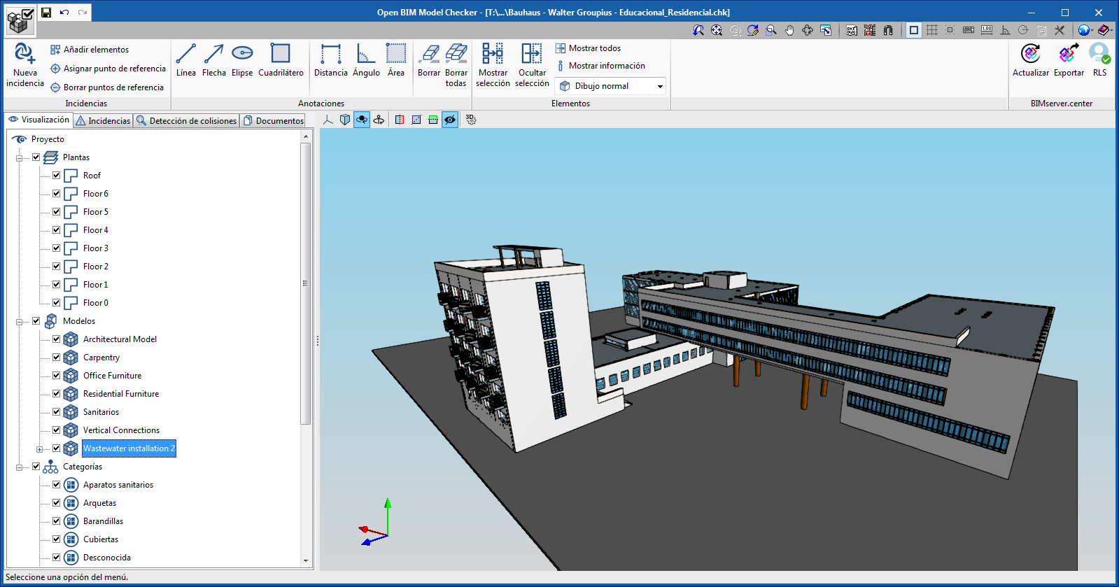
The 2020.c version of “Open BIM Model Checker” includes new features that notably increase its potential. New features have been included in the visualisation of the project, incident management, automatic detection of collisions, and access to and visualisation of the project documents.
Information on the program can be found on the Open BIM Model Checker webpage (including the new features of the program). The new features of this version are summarised in the following sections.
Visualisation improvements
To help users with the inspection process of the geometric model, the program provides three visualisation options:
- View by floors
- View by discipline
- View by elements
More information can be found in the “Visualisation” section of the Open BIM Model Checker webpage.
Incident management improvements
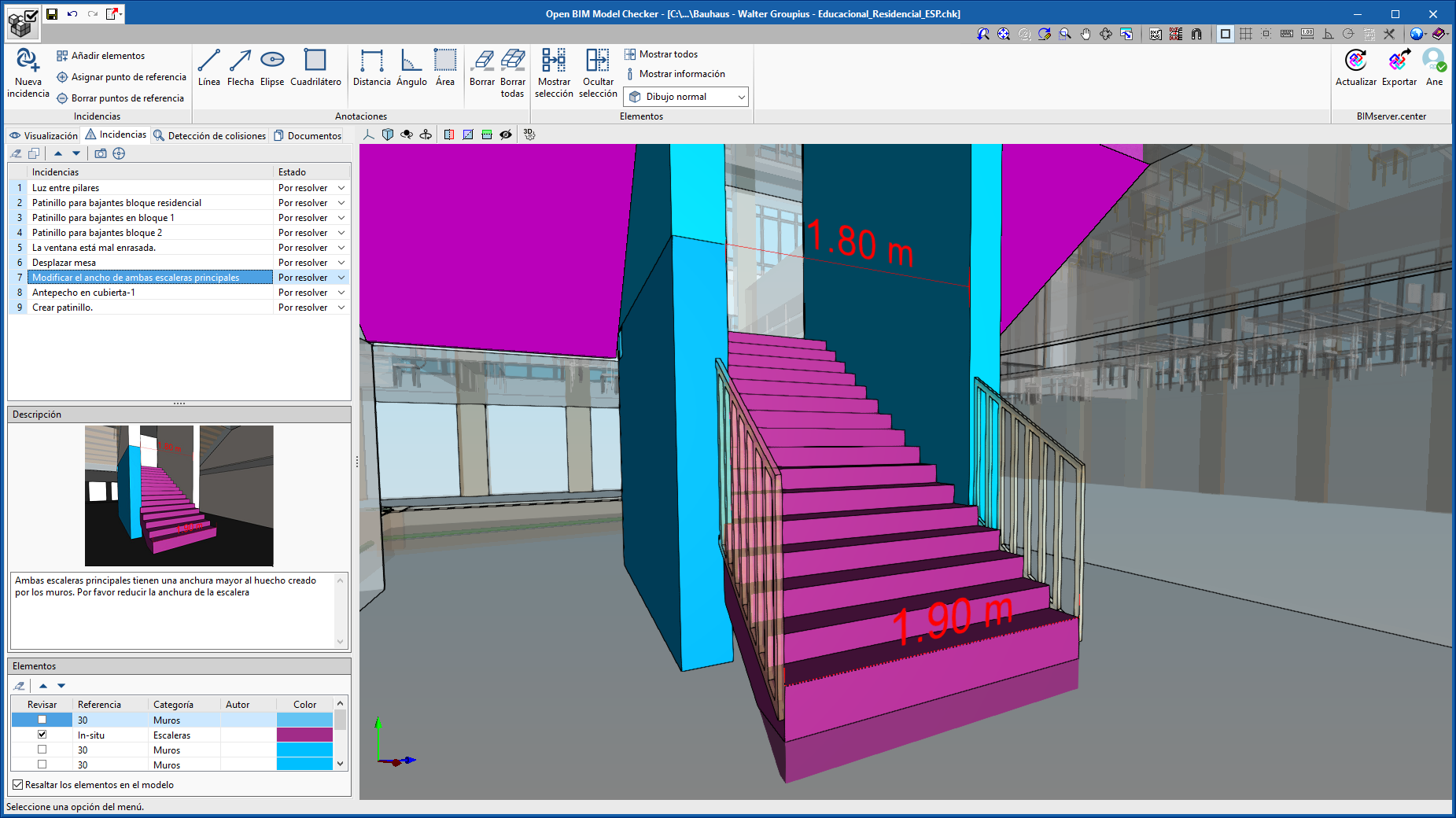
Annotation tools have been included so users can draw directly on the 3D model (draw lines, arrows, ellipses and rectangles, and include measurements).
More information can be found in the “Incidents – Annotations” section on the Open BIM Model Checker webpage.
Collision detection
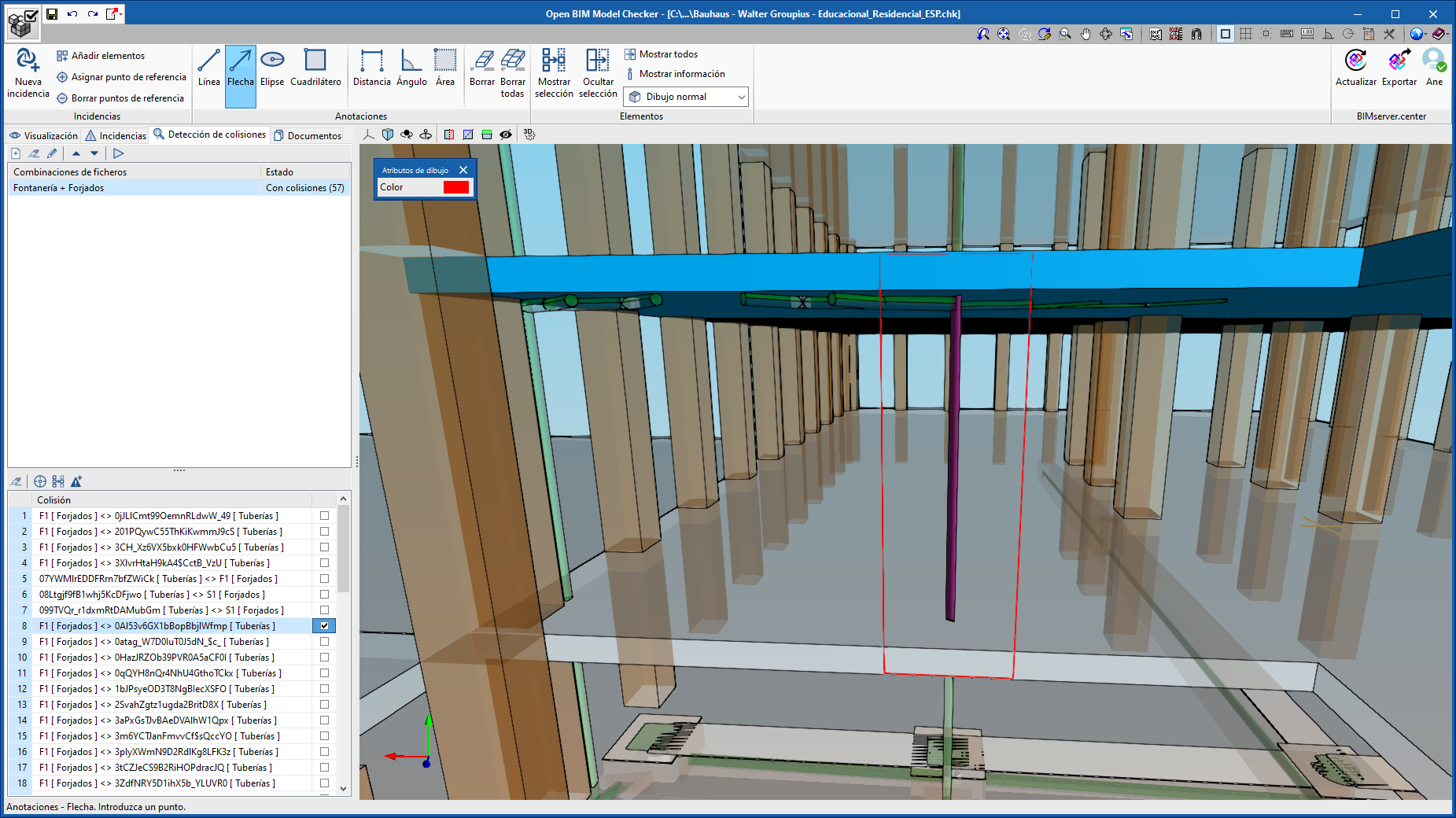
“Open BIM Model Checker” automatically detects if there are any collisions between the different disciplines of the project, for example, between the building services installations and the structure, where it detects any possible layout errors of any of the elements of these disciplines (such as a pipe running into a column).
Even though “Open BIM Model Checker” is a free tool, users require the corresponding permit of the user license to be able to detect collisions.
More information can be found in the “Collision detection” section on the Open BIM Model Checker webpage.
Access and visualisation of BIM project documents
Users can now access all the information associated with the IFC files that are exported by each discipline to the project located on the BIMserver.center platform. This way, users cannot only access the geometric model of the project from "Open BIM Model Checker", but also all the documents that are associated with it (PDF, DWG...).
More information can be found in the “Document access and visualisation” section on the Open BIM Model Checker webpage.
CYPECAD
Timber columns (CYPECAD module)
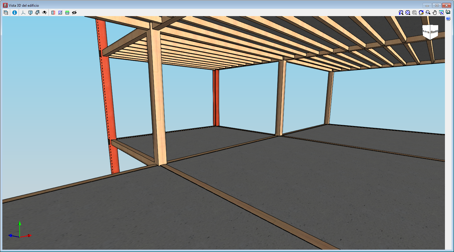
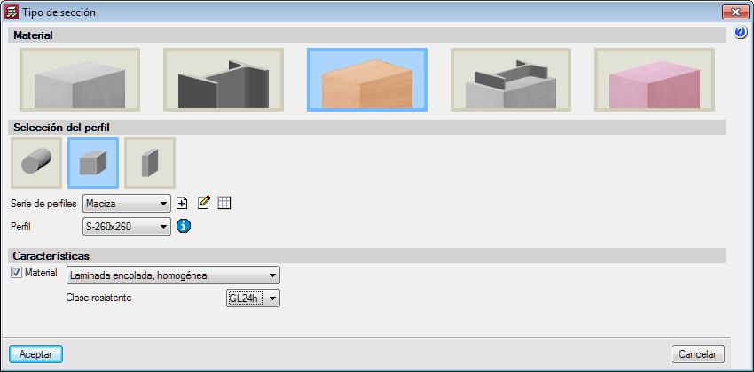
With the “Timber columns” module, CYPECAD can analyse and design timber columns with rectangular and circular sections.
The codes that have been implemented to design and check timber columns are:
- ANSI/AWC NDS – 2015 (ASD) (USA)
- CIRSOC 601 (Argentina)
- CTE-DB-SE-M (Spain)
- Eurocode 5
- Eurocode 5 France
- Eurocode 5 Belgium
- NBR 190:1997 (Brazil)
More information on Timber columns.
Options to import floor slab outlines from the BIM model
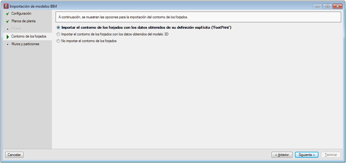
Several options have been implemented in CYPECAD to import floor slab outlines:
- Import floor slab outlines with the data obtained from explicit definition (FootPrint).
- Import the floor slab outlines with the data obtained from the 3D model.
- Do not import floor slab outlines.
The architectural models can contain different information depending on the program and the program version that has generated them. Some programs export the floor plan representation of the floor slabs (FootPrint) as well as the 3D model. Up until the 2020.b version, CYPECAD imported the representation of the floor slabs (FootPrint) if it had been defined, otherwise, it offered users the possibility to import them based on the 3D model.
These import options have been implemented because errors were observed in the IFCs that came from the latest versions of some programs, where the outlines were exported correctly but the outlines of the openings were not exported.
Improvements in the column introduction and editing panel
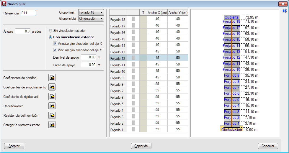
The appearance of the dialogue box where columns are introduced and edited has been modified. The table where users can edit the geometry of the column at each floor has been moved to the right of the column data.
With the distribution that existed in previous version, users could not view all floors simultaneously if the structure contained a high number of floors.
Options to manage beam alignment references
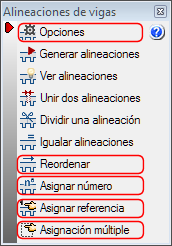
Some options (Options, Reorganise, Assign number, Assign reference and Multiple assignment) have been grouped or added in the “Beam alignment” panel (“Beam Definition” > Beams > Beam alignments).
Please note that, as of the 2020.c version, beam alignment references will remain even if beams are added or deleted.
Options
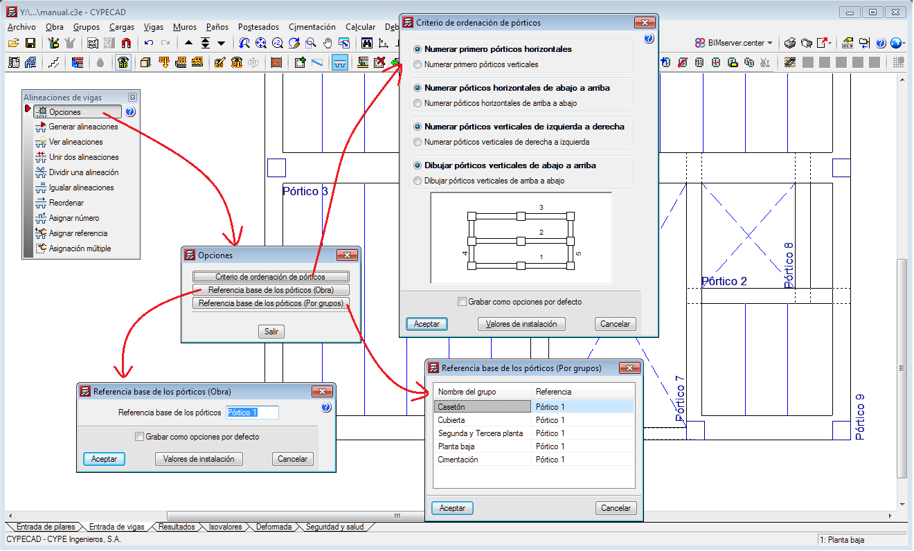
The following existing tools have been grouped in Options:
- Frame order criteria
- Base reference of the frames (Project)
- Base reference of the frames (By group)
Reorganise
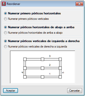
Using this tool, users can reorganise the frames depending on their position on-plan.
Assign number
This option allows users to assign a different alignment or frame number to the one that has been generated automatically by the program in accordance with the criteria that has been specified in “Generate alignments”.
Assign reference
With this option, users can assign a reference to an alignment.
Multiple assignment
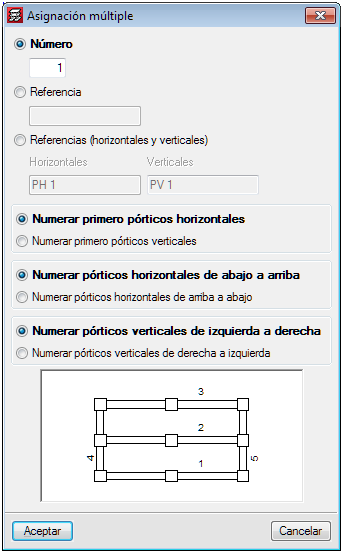
Using this tool, users can assign the following data to a selection of alignments:
- Number
The first number from which the numbers will continue is defined here. - Reference
Users define the reference of the first frame, as of which the remaining references will be assigned by increasing the last symbol alphabetically or numerically. - References (horizontal and vertical)
The references of the first vertical and first horizontal frames are defined, as of which the remaining references will be assigned by increasing the last symbol alphabetically or numerically.
Move texts, introduced in “Editing resources”, from the “Drawings editor” of the “Drawing composition”
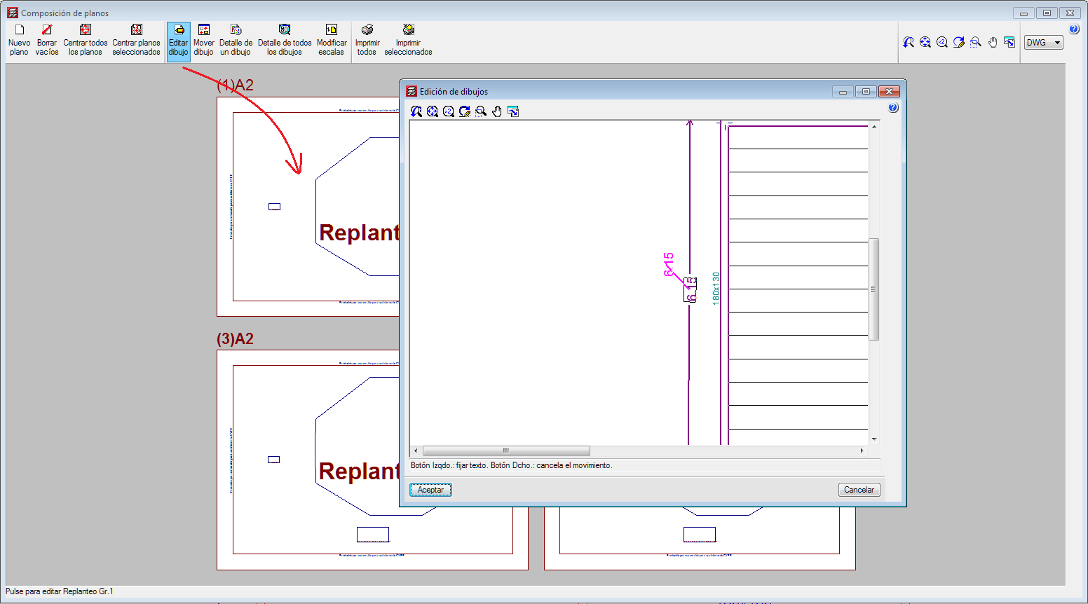
A new option has been implemented to change the position of texts that have been defined using the “Editing resources” tools from the “Drawing editor” of the “Drawing composition”.
Wind load justification report for “NBR 6123” and “NF EN 1991-1-4/NA”
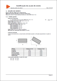
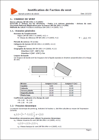
In the 2020.c version, the “Wind load justification report” has been implemented for the following codes:
- NBR 6123
Forças devidas ao vento em edificações (Brazil) - NF EN 1991-1-4/NA
Document National d’Application pour la France.
Eurocode 1: Actions sur les structures.
Partie 1-4: Actions générales – Actions du vent.
This report was implemented for other codes in previous versions and will continue to be implemented for others progressively.
CYPECAD and CYPE 3D
New section library
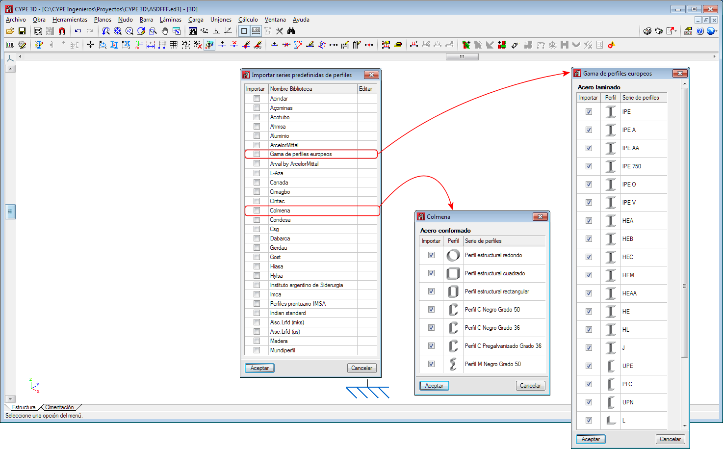
Two new section libraries have been implemented:
- Range of European sections (Section series adapted to EN 10365: 2017 and EN 10056: 2017)
- Colmena
StruBIM Design Shear Walls
Draw horizontal reinforcement in shear wall sections
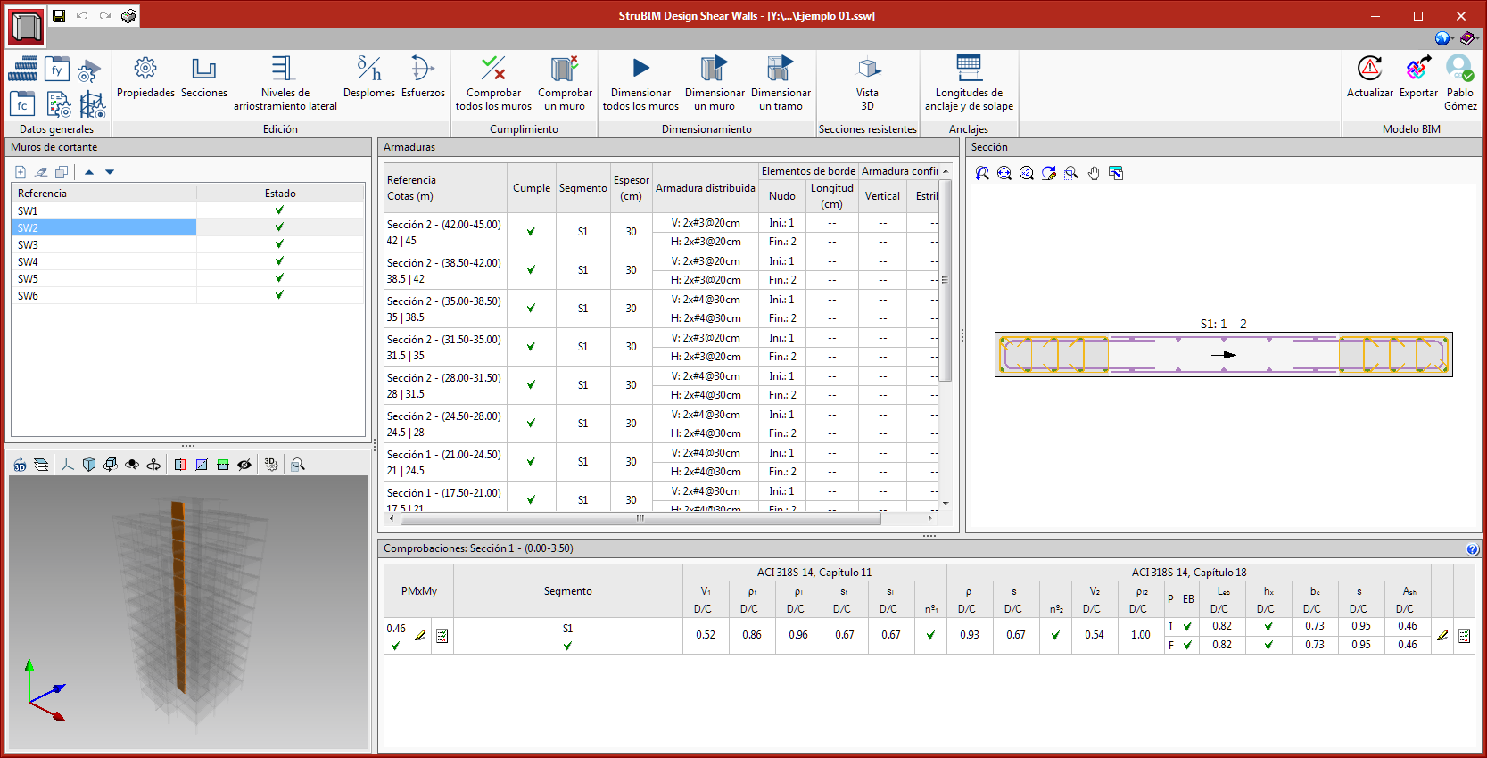
The horizontal reinforcement of walls is now drawn in the view of the transverse section.
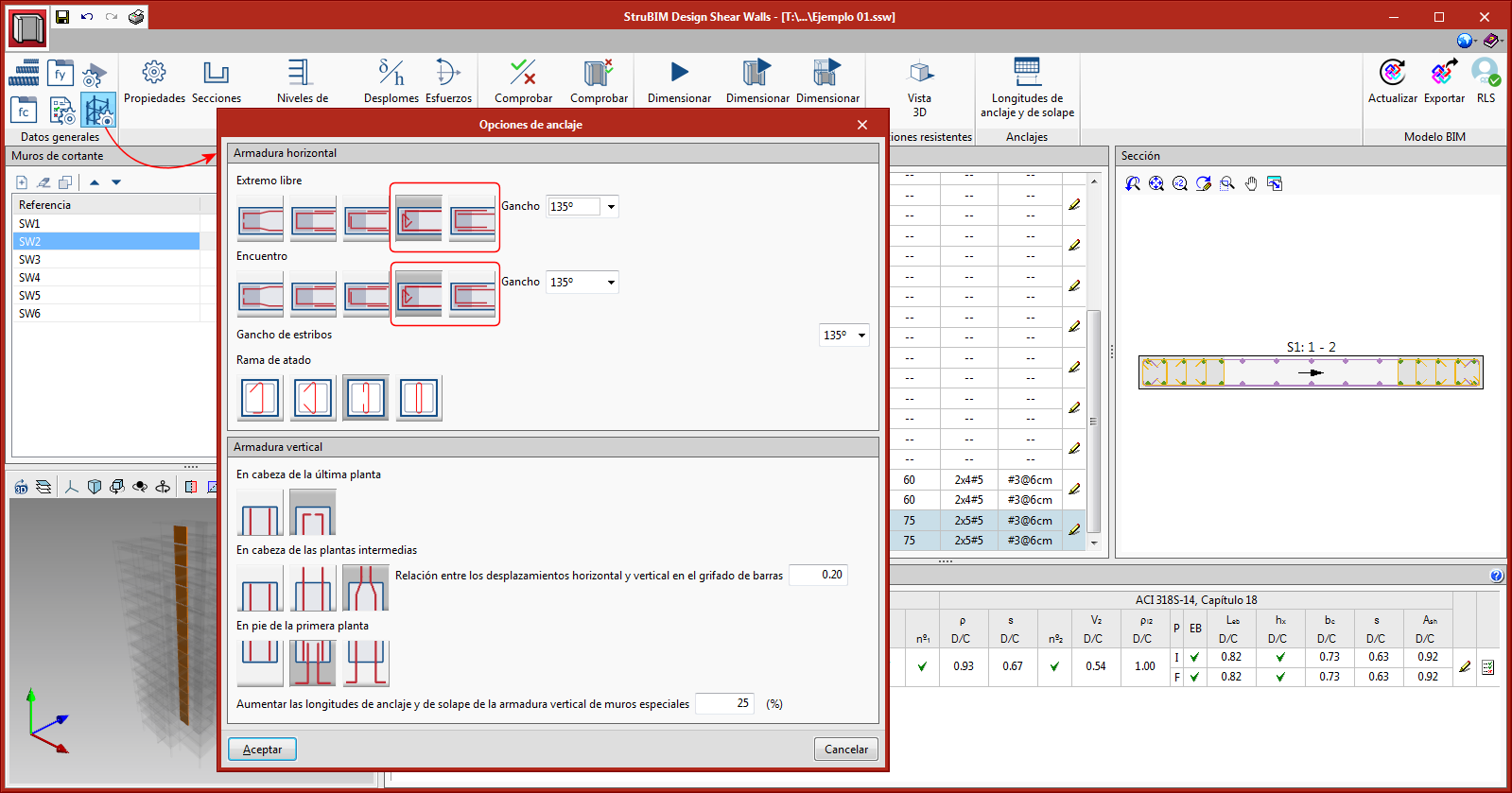
The anchorage and reinforcement layout options will affect this drawing and the export to materialise the arrangement in StruBIM Rebar.
Segments with confined reinforcement
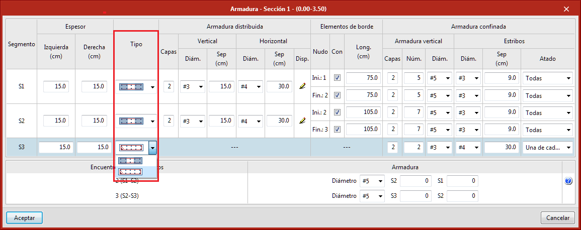
Until the 2020.b version, the reinforcement of the segments was composed of reinforcement that was distributed in layers and additionally could have edge elements at the ends.
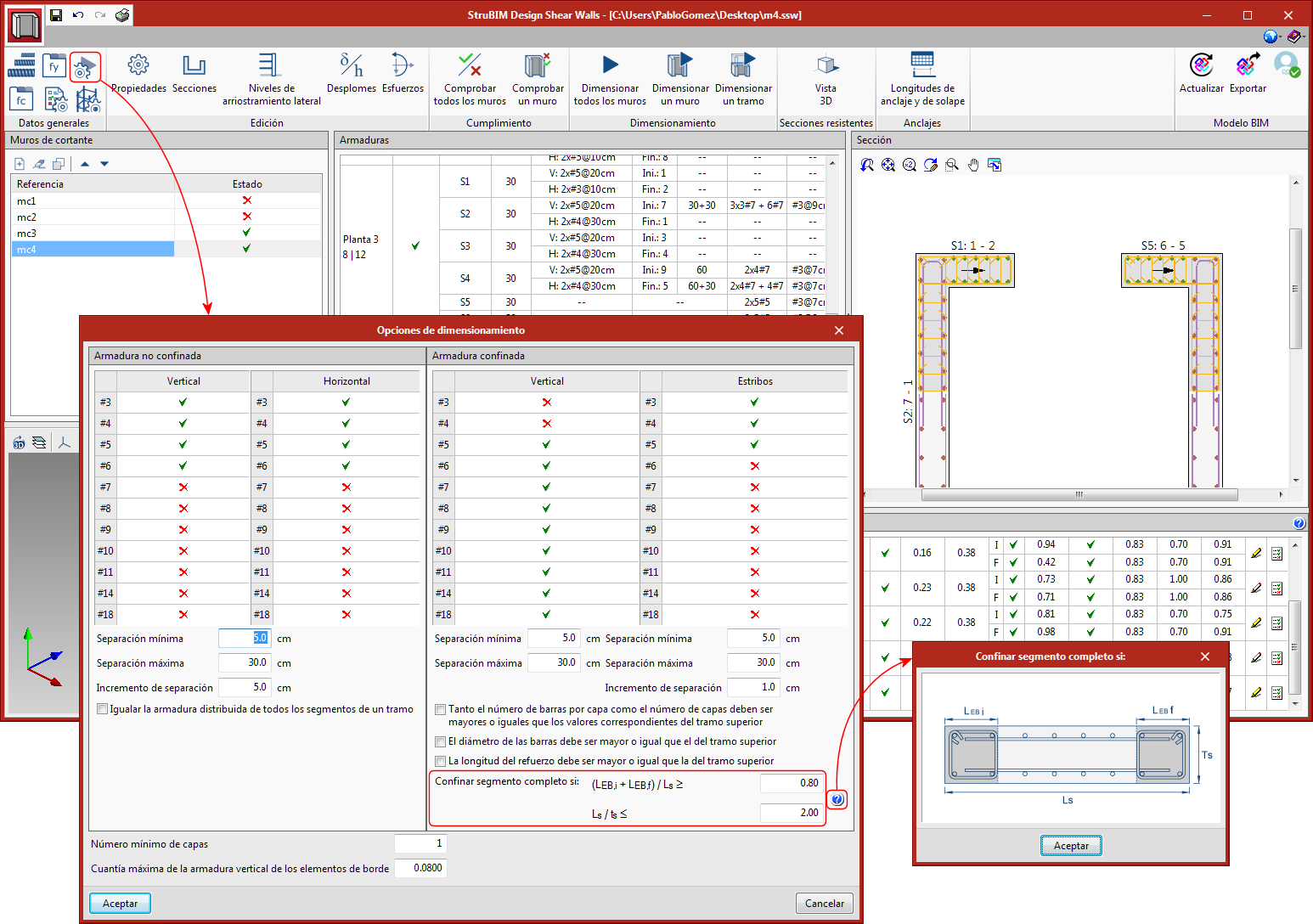
In the 2020.c version, users can define confined reinforcement along the whole segment. The length of the edge elements is not checked in this type of segment because the entire segment is considered to be confined.
During the design process, the program analyses, for each segment, whether edge elements must be provided and their required length. In the design options, two limits have been included to determine whether or not confinement reinforcement is to be placed throughout the entire segment; one that depends on the lengths of the edge elements and another that depends on the length to thickness ratio of the segment.
Multiple reinforcement editing
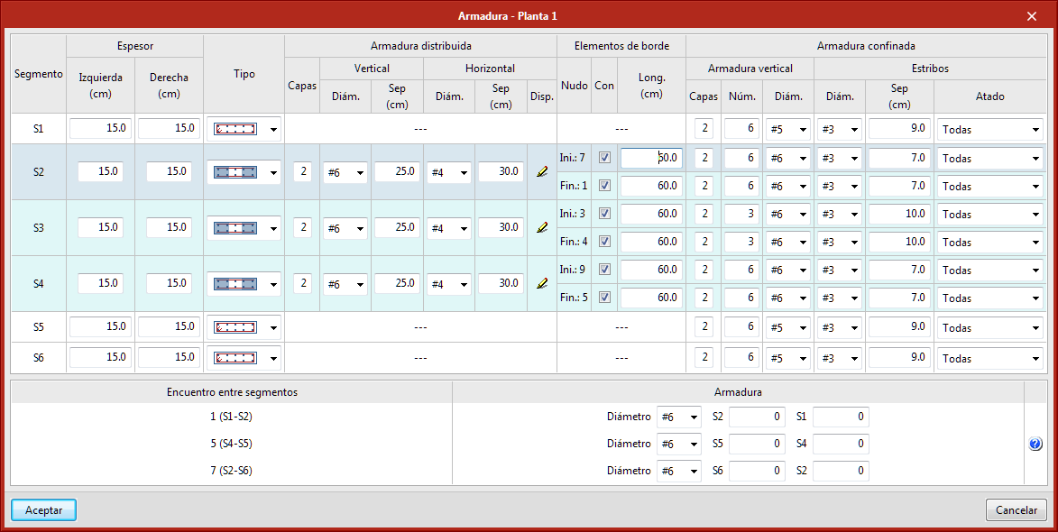
Multiple editing of segment reinforcement is now possible with the 2020.c version. If users select several rows of the reinforcement definition table, any changes carried out on one cell will be reflected in the other cells of the same column that have been included in the selection. In other words, any changes carried out on one segment will be applied to all the selected segments.
In the table, the selected segments will have a shaded background. Segments can be selected by pressing, with the left mouse button and the Control key, any point of the row or using a capture window.
Edit the number of bars at segment intersections
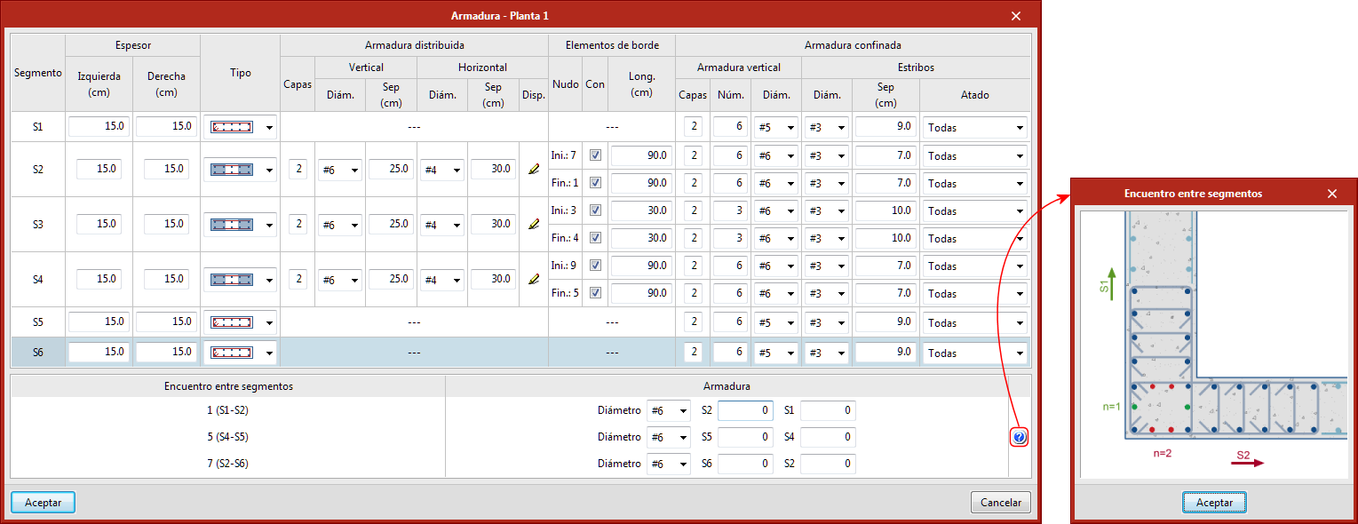
Users can edit the number of bars at segment intersections. For each intersection, the diameter of the reinforcement and the number of bars in the faces of the direction of each segment can be edited.
Undo/Redo
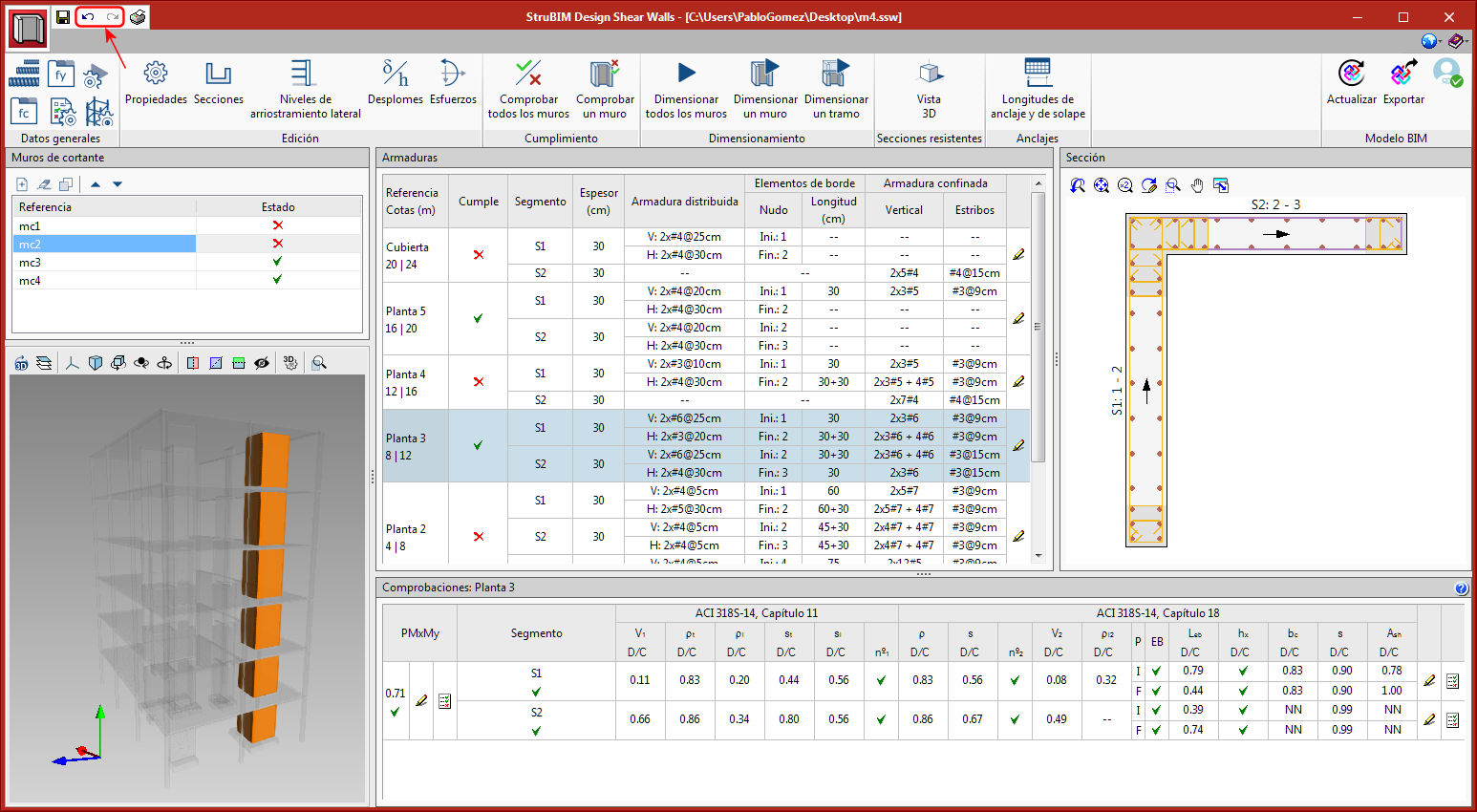
Undo and Redo options have been implemented.
StruBIM Design Shear Walls and StruBIM Rebar
New types of horizontal reinforcement
Two new types of horizontal reinforcement at segment ends have been implemented:
- Extend with “L” anchor
- Extend with hook
CYPECAD MEP
Export bill of quantities to the BIM project
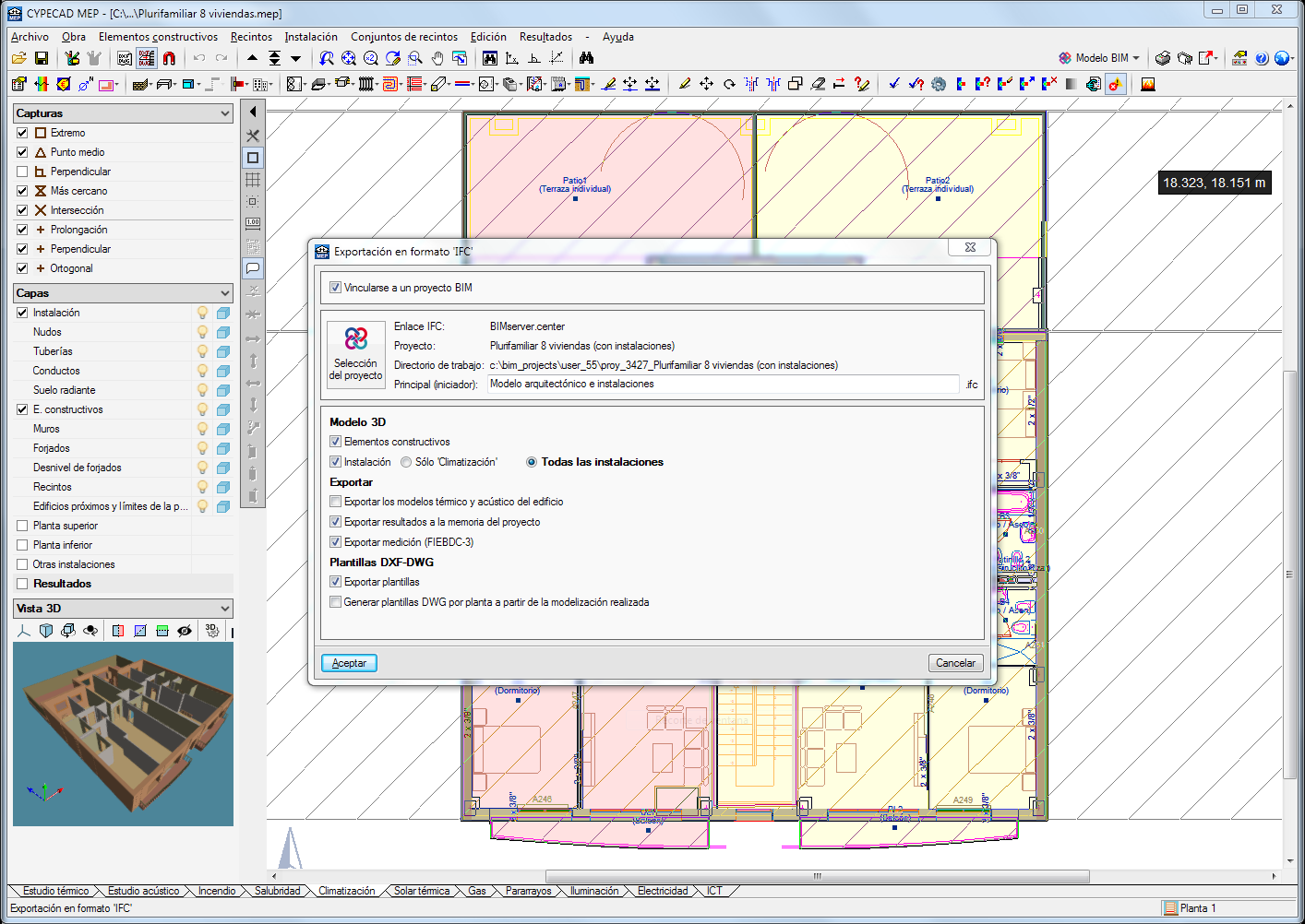
As of the 2020.c version, CYPECAD MEP allows users to export the bill of quantities of the building installations and construction elements of the project, in FIEBDC-3 format (.bc3), to the linked BIM project located on the BIMserver.center platform. This information is generated automatically, is available to all the members of the project work group and can be downloaded to then import it in budget management programs such as Arquimedes.
The prices are obtained from the Price Generator. Therefore, users must have the required license permits to use the connection to CYPE’s Price Generator.
In the “Export” menu of the “Export in IFC format” panel of CYPECAD MEP, users can activate the “Export quantities (FIEBDC-3)” option.
CYPETEL Schematics
Report of the fibre optic network results
As of the 2020.c version, the program generates a report containing all the attenuation results of the designed fibre optic networks.
CYPETEL Systems
Visualisation modes
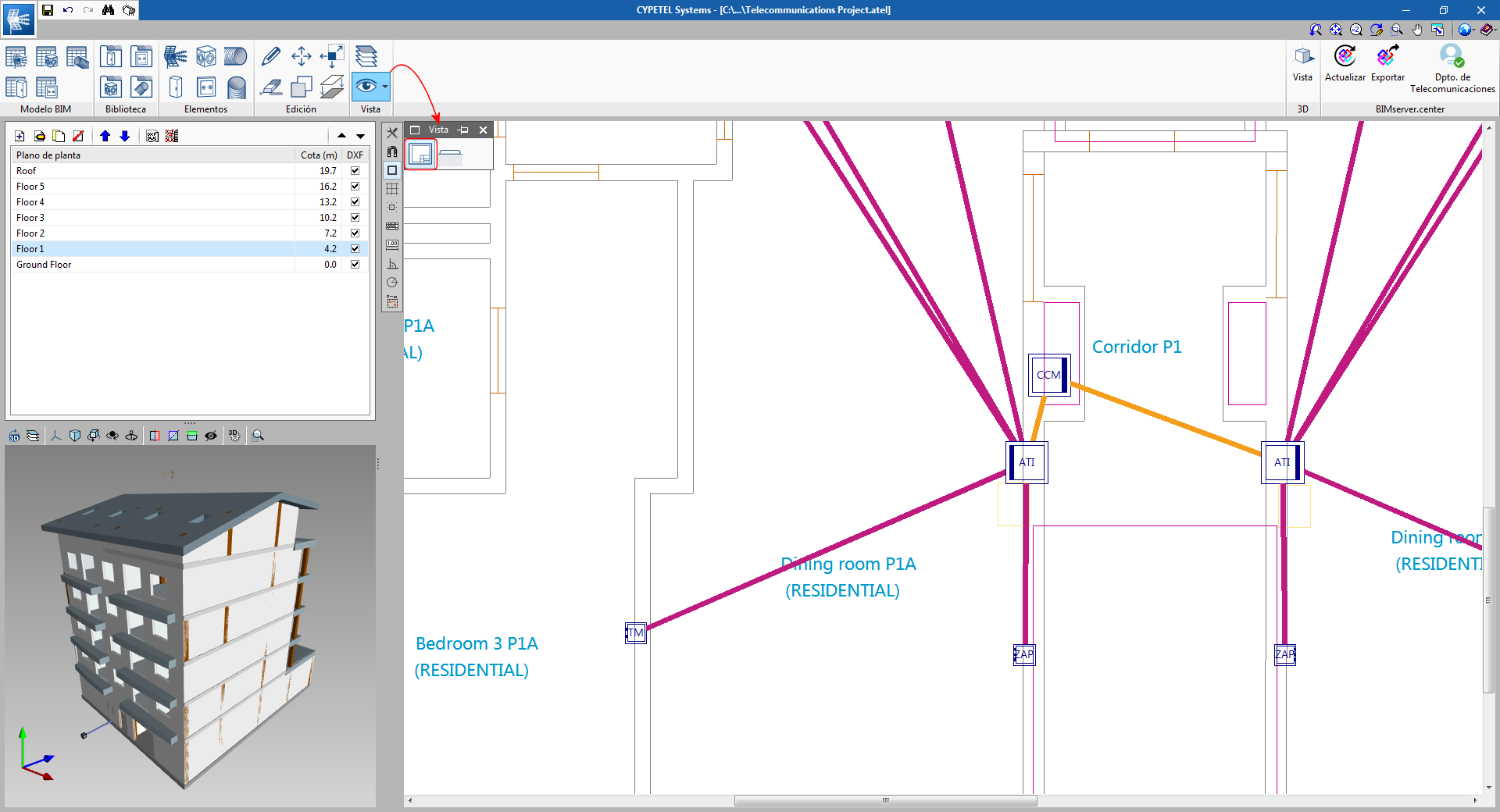
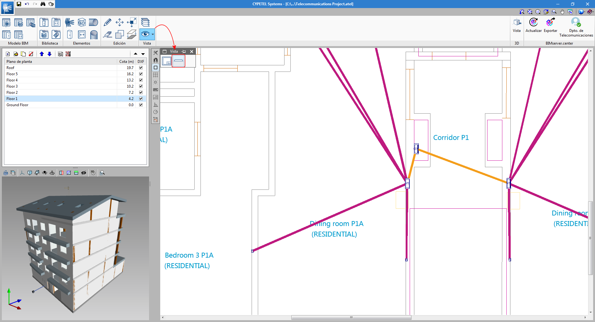
A new tool has been included, which can be used to modify the way elements are viewed on-plan, so they can be represented in accordance to users’ needs.
CYPELEC PV Systems
Program restructuring
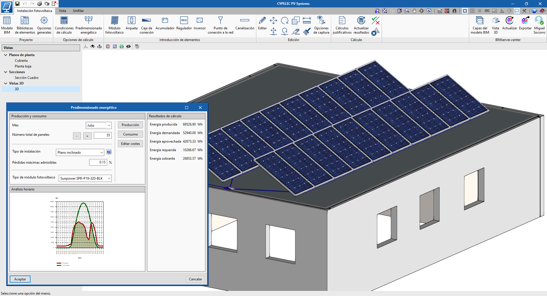
An important evolution has been developed in "CYPELEC PV" (the design tool for photovoltaic installations). The work interface has been changed from a 2D environment to a spatial layout in 3D, but templates are still used to carry out the work thanks to the view manager. To distinguish this program version from the previous version, the program has been renamed CYPELEC PV Systems.
The new "CYPELEC PV Systems" interface allows elements to be arranged independently, so the general analyses are now performed from element to element. With this change, there is greater versatility when defining different types of installations, whilst maintaining all the functionalities of the previous version.
The results output provides the calculated values and the checks that have been carried out on each element, as well as a general justification report of the installation.
Due to the code restructuration that has been performed on the program, projects that have been designed with previous versions (CYPELEC PV) cannot be read from “CYPELEC PV Systems”. Users who wish to manage projects from CYPELEC PV can continue to do so using the 2020.b version of the program.
Available in English
“CYPELEC PV Systems” can now be installed in English.
CYPETHERM programs with the EnergyPlus™ analysis motor (CYPETHERM EPlus and CYPETHERM RECS Plus)
DHW systems with several production units
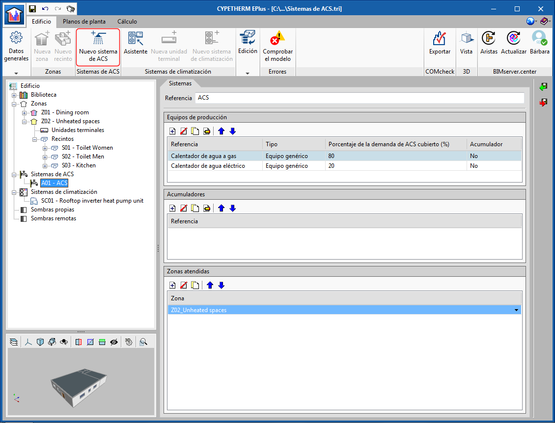
The ability to define several production equipment sets associated with a DHW system has been added. Users must indicate what percentage of the DHW demand that is associated with the system covers each defined equipment set.
As in previous versions, DHW systems are defined in the "DHW Systems" diagram section. If the "Total building demand" option has been selected in "General parameters", users can define the DHW system of the building directly by clicking on "DHW Systems" in the diagram.
If the “Demand by thermal zone” option has been selected, the “New DHW system” button of the toolbar must be used to define the DHW systems. This new function allows users to define the DHW systems that see to the different areas of the building, in a single step.
Water-condensation system at a specific temperature
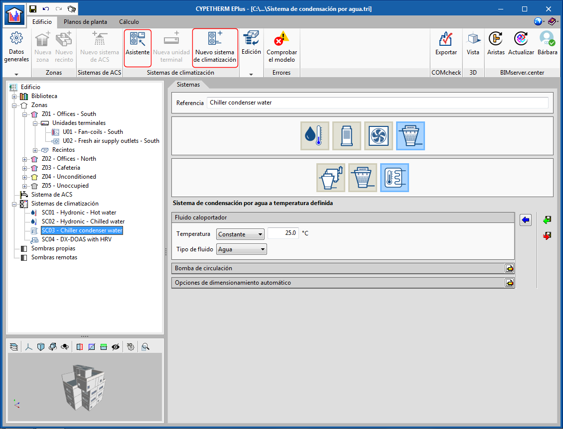
Within the "Water-condensation systems", a "Water condensation system at a specific temperature" has been added. This type of system can simulate any water or glycol circuit connected to the external exchangers of the air conditioning equipment. For example, it can be used to simulate a field of geothermal collectors or a groundwater stream. To do so, users must only define the temperature of the fluid at the circuit outlet and the properties of the circulation pump.
This new condensation system is compatible with coolers and outdoor VRF units with water-cooled condensers, as well as with water-air heat pumps.
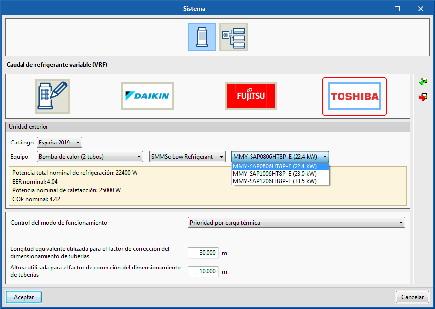
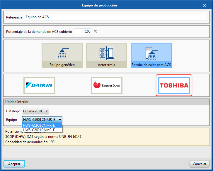
Update of the TOSHIBA air conditioning and DHW equipment catalogue
New references of the 2019 Toshiba VRF equipment and aerothermal equipment catalogue have been included. Additionally, heat pumps for DHW from this manufacturer have been added within the DHW production equipment.
CYPETHERM programs with the EnergyPlus™ analysis motor and CYPETHERM LOADS
URSA materials and construction solutions
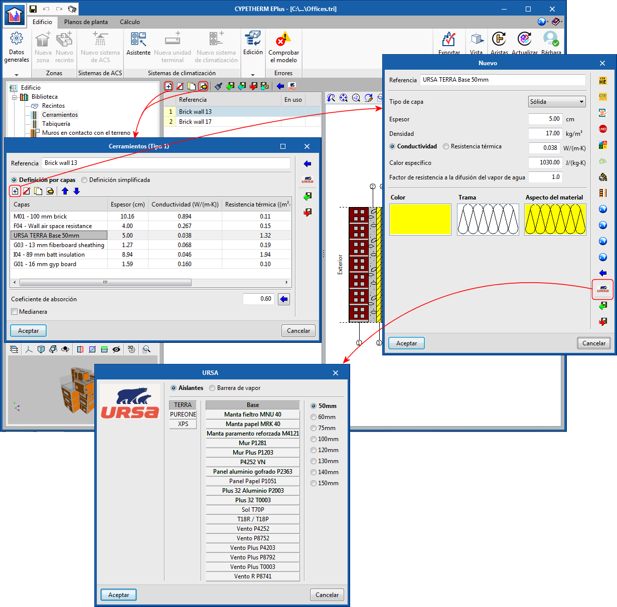
Insulating materials and vapour barriers offered by the manufacturer URSA have been included within the libraries of opaque construction elements of the building (façades, roofs, etc.). Users can choose amongst the materials in the URSA catalogue, when defining the layers of the construction elements of the building, by clicking on its logo. The properties of these materials are completely defined.
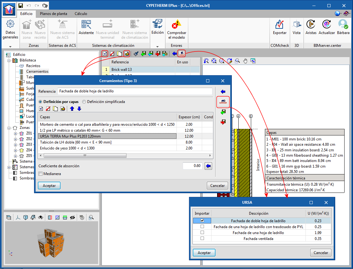
Furthermore, assistants with usual construction solutions, without insulation and with URSA insulation, have been added for façades, partitions, walls and floors in contact with soil, floor slabs between floors, and roofs. Users can import these predefined solutions by clicking on the URSA logo in the corresponding library panel, or when defining a new item.
CYPETHERM Eplus
DHW accumulators
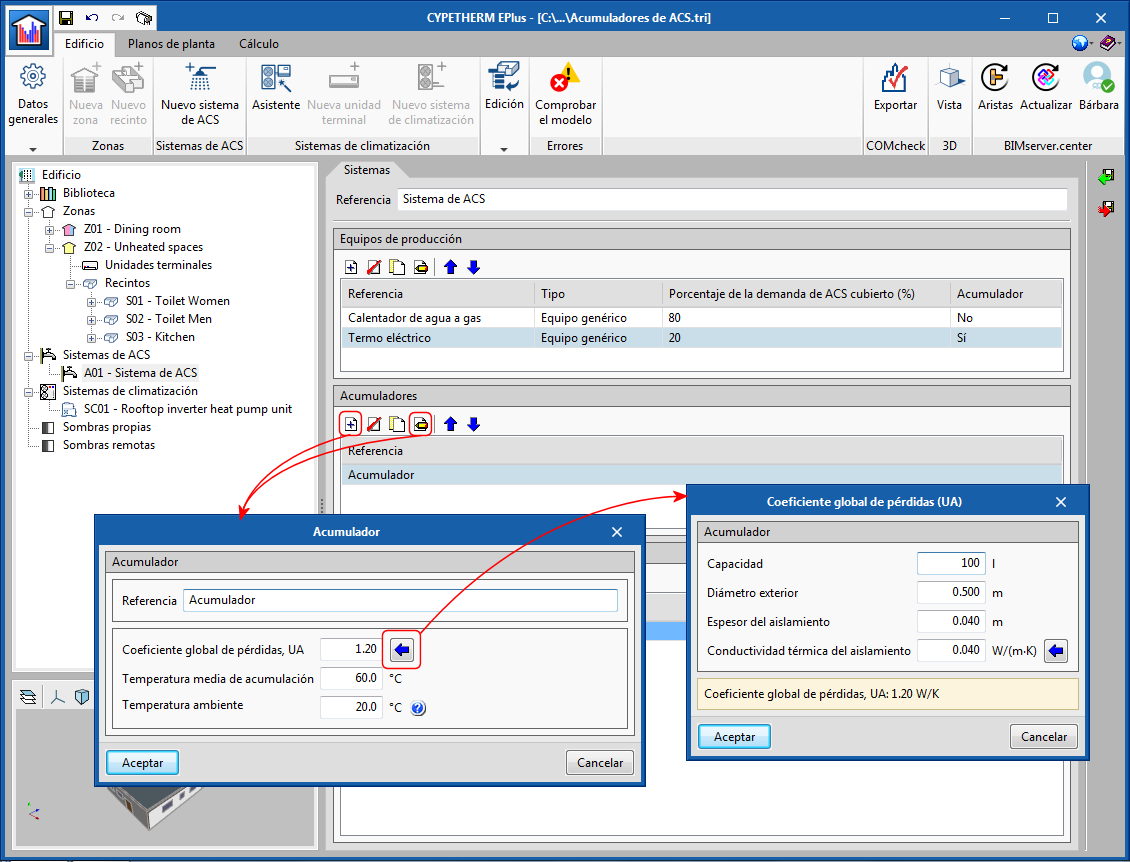
Within DHW Systems, users can now define DHW accumulators, to be able to account for the effect of their heat losses on energy consumption for this building service.
The DHW accumulators are defined within the corresponding DHW System, using their global loss coefficient (UA). An assistant is provided to calculate the UA value of the accumulator based on its dimensions and its insulation properties. The heat losses produced in the DHW accumulators represent an increase in the demand for energy, which will be provided by the production equipment that is associated with the same DHW system.
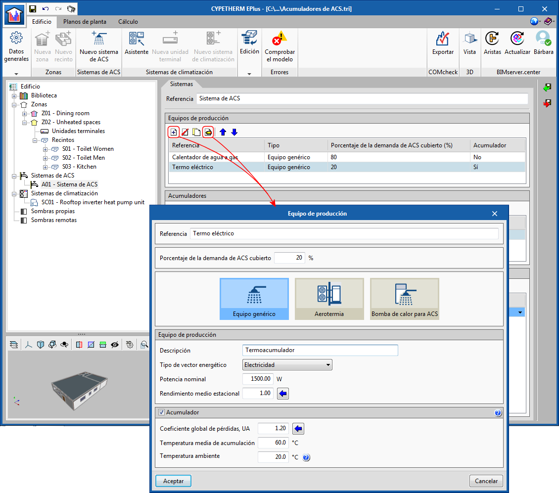
An accumulator associated with a specific DHW production equipment set can also be defined. In this case, heat losses due to the accumulation will be compensated only by that production equipment. This option allows users to define equipment such as electric heat accumulators or heat pumps for DHW.
VAILLANT geothermal heat pumps
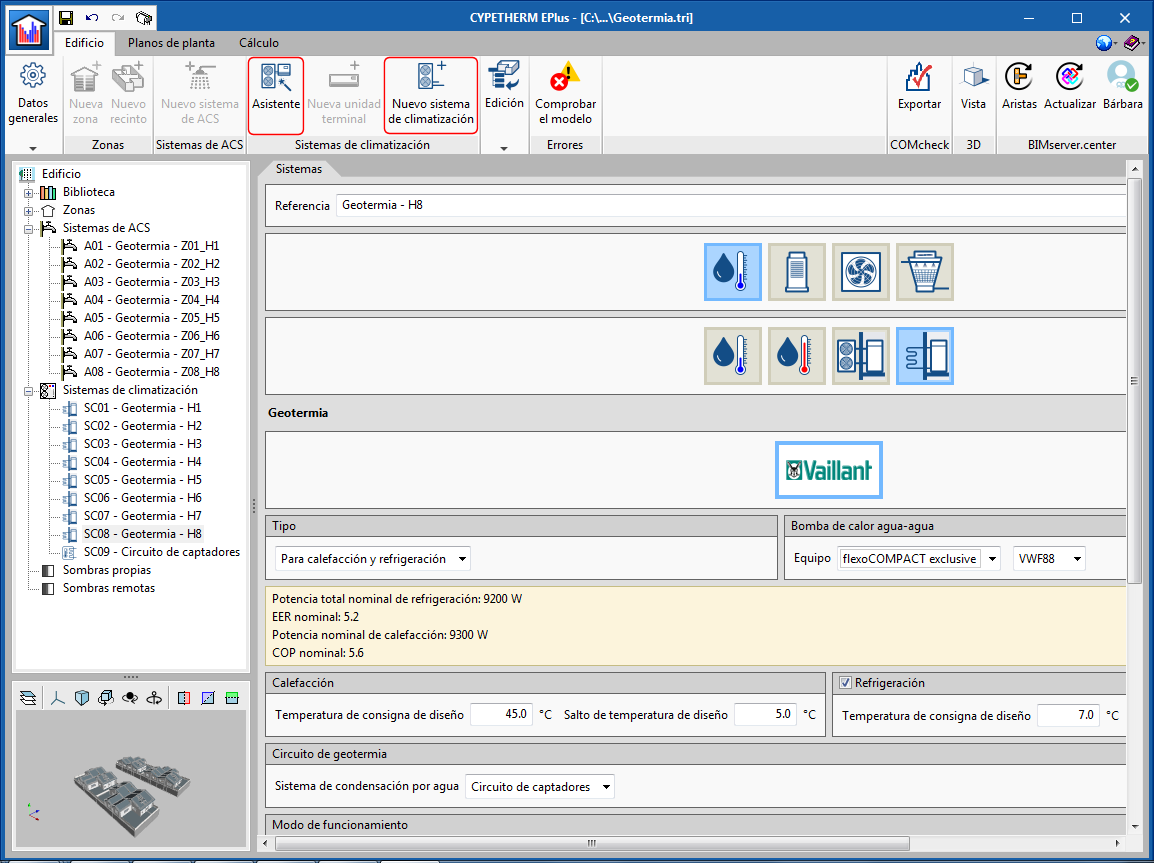
As of its 2020.c version, CYPETHERM EPlus is capable of simulating air conditioning systems with air-water heat pumps based on the behaviour curves of this equipment, and incorporates the VAILLANT geothermal heat pump catalogue.
Geothermal water-water heat pumps appear as a new category in "Water-air conditioning systems". In the panel that appears when clicking on the new "Geothermal" button, users can choose amongst different models of VAILLANT geothermal heat pumps for heating (geoTHERM series) or reversible (flexoTHERM and flexoCOMPACT series). Additionally, users must specify the operating conditions of their installation.
The geothermal heat pump must be connected to a water condensation system at a defined temperature, also available as of version 2020.c of the program. This type of system allows users to simulate the conditions of the fluid at the inlet of the outdoor side of the heat pump, for example from a collector circuit.
Geothermal heat pump systems can be connected to terminal units such as radiators or radiant floors (heating only) and to fan coil units (heating and cooling).
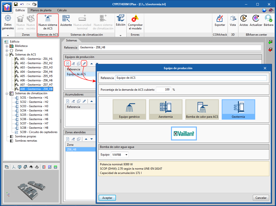
Furthermore, geothermal heat pumps have been included within the DHW production equipment. In this panel, users can choose between the different VAILLANT flexoCOMPACT series models.
Using the "Assistant" button of the toolbar, the program will guide users when creating a geothermal air conditioning and DHW system, allowing them to select the appropriate terminal units, heat pump and condensation system consecutively.
Open BIM workflow. Import air conditioning equipment from “Open BIM SAUNIER DUVAL”
SAUNIER DUVAL aerothermal equipment and fan coils defined in "Open BIM SAUNIER DUVAL" can be imported directly into CYPETHERM EPlus via the Open BIM connection using the IFC standard. If this equipment is associated with a CYPETHERM Hydronics project, the connections between them will also be imported.
Return to the 2020 version download area
Tel. USA (+1) 202 569 8902 // UK (+44) 20 3608 1448 // Spain (+34) 965 922 550 - Fax (+34) 965 124 950