
NEW FEATURES OF EXISTING PROGRAMS
- Improvements common to all programs
- Open BIM FUJITSU
- Open BIM MOVAIR
- Open BIM ROTH
- Open BIM TOSHIBA
- Code implementation and improvements in its application
- CYPECAD
- CYPECAD, CYPE 3D, Embedded retaining walls, Reinforced concrete cantilever walls, Foundation elements and Box culverts
- CYPECAD MEP
- Open BIM Stairs & Ramps – Open BIM Vertical Connections
- Open BIM Model Checker
- CYPELEC Electrical Mechanisms
- CYPELEC Networks
- CYPEPLUMBING Water Systems
- CYPEPLUMBING Water Systems, CYPEPLUMBING Solar Systems and CYPEHVAC Hydronics
- CYPEPLUMBING Sanitary Systems
- CYPEPLUMBING Sanitary Systems and CYPEPLUMBING Water Systems
- CYPEHVAC Ductwork
- CYPETHERM EPlus
- Return to the 2020 version download area
Improvements common to all programs
Quick access from “File Manager”
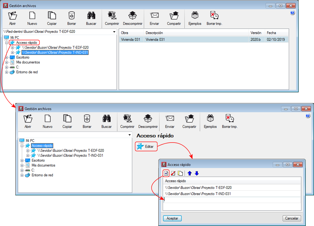
As of the 2020.b version, users can, for all CYPE programs, create a quick access to folders (local or network) in the "File Manager" panel. This panel opens when users wish to open a project from CYPE programs.
This way, users can quickly access the paths where their projects are saved.
To do so, a "Quick Access" option has been included in the "File Manager" dialogue. When this option is selected, users can save any location (local or network) to access it at any other time.
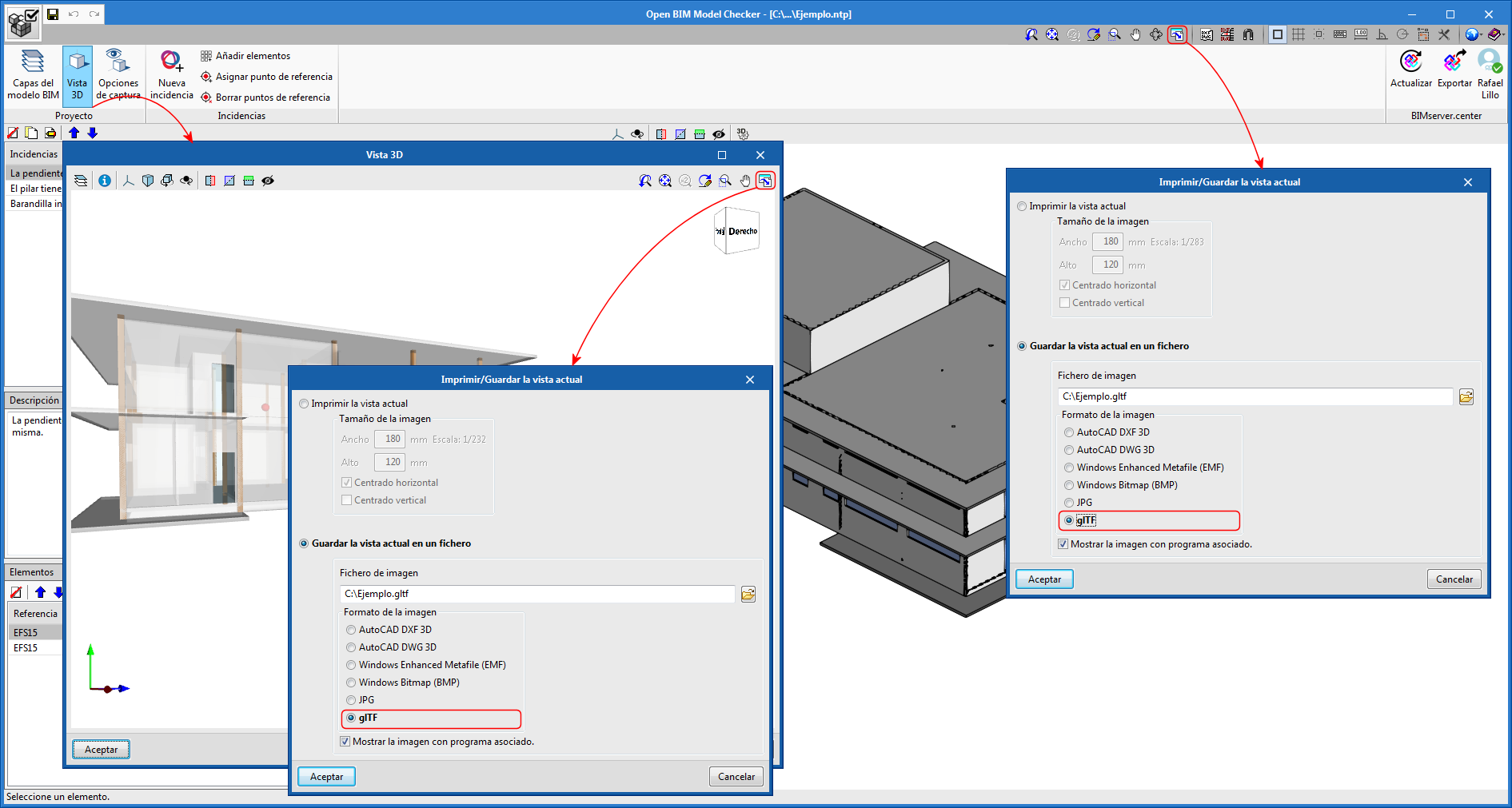
Export the current 3D view to glTF format
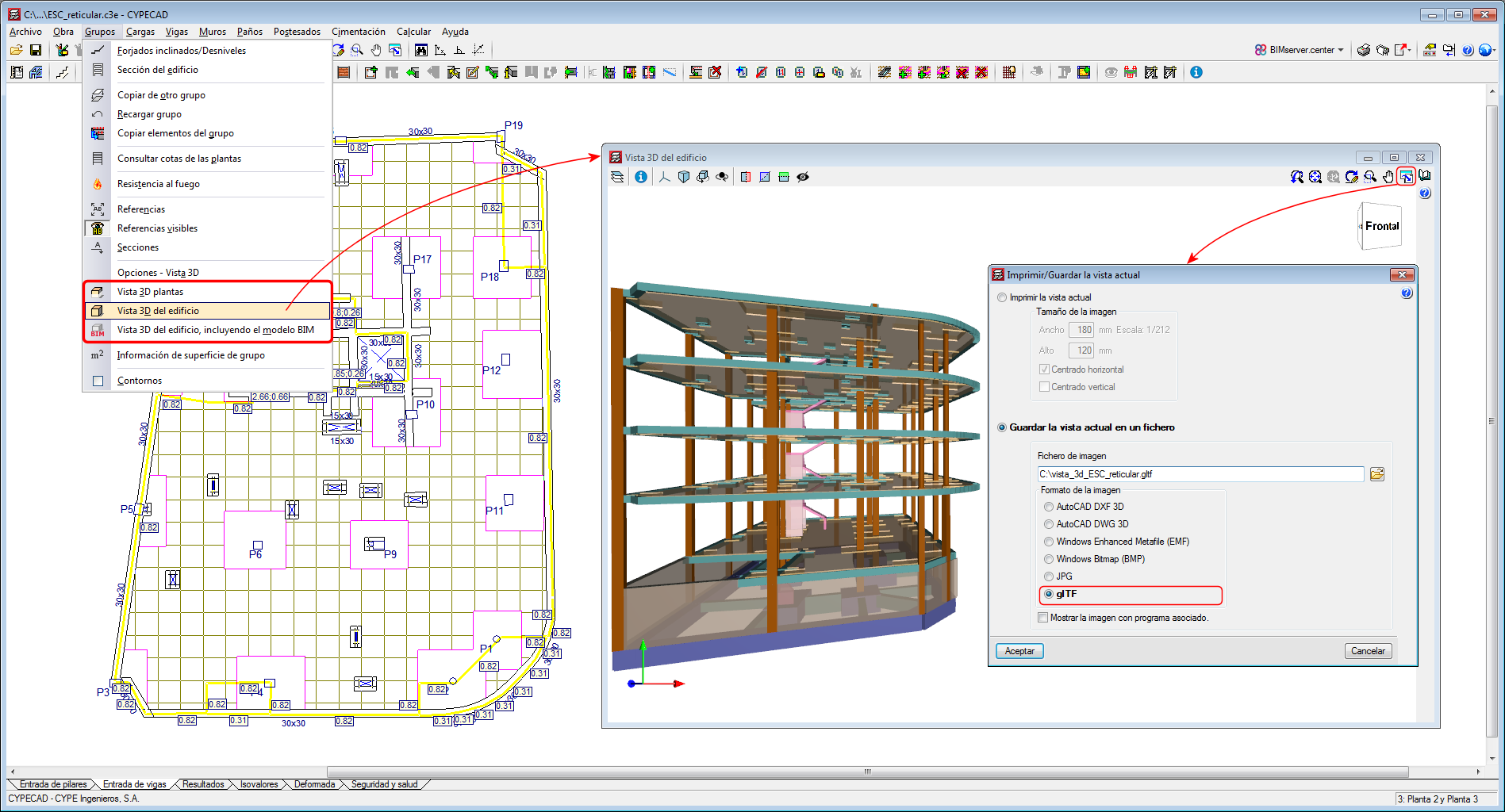
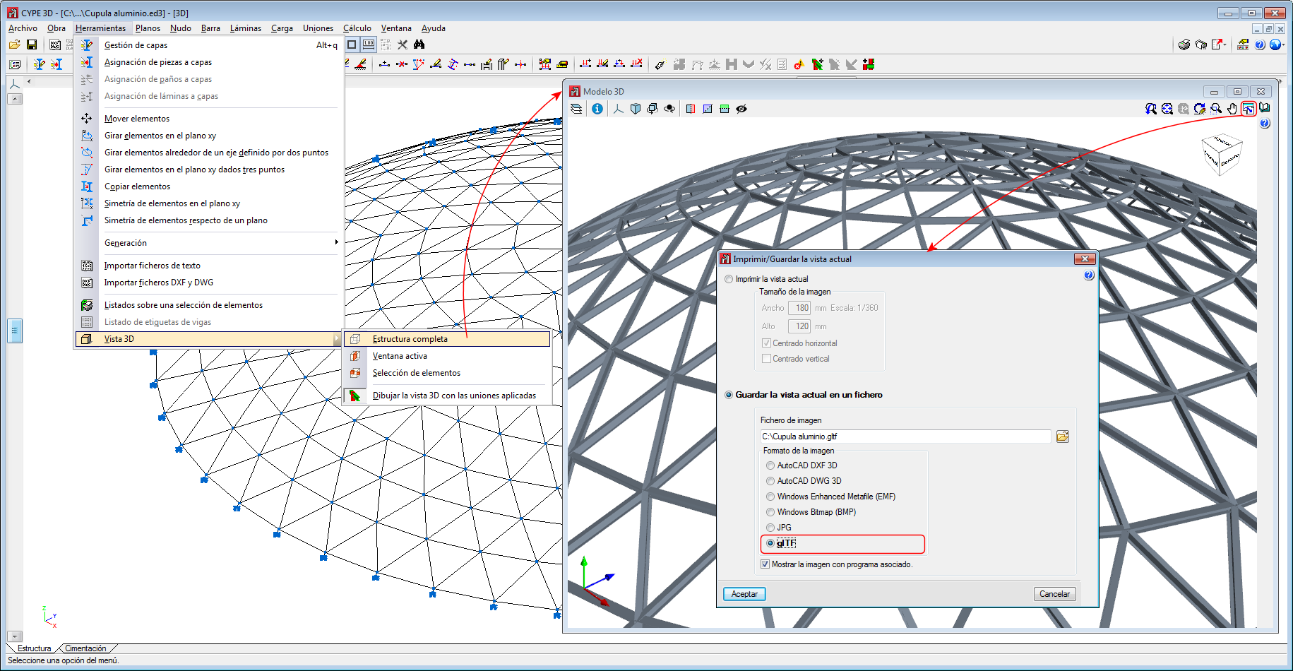
The 3D views provided by CYPE programs can be exported to "glTF" format using the "Print current view" option. This option is available in the CYPE program windows in which 3D views are generated.
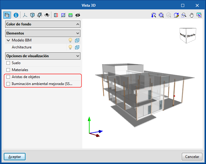
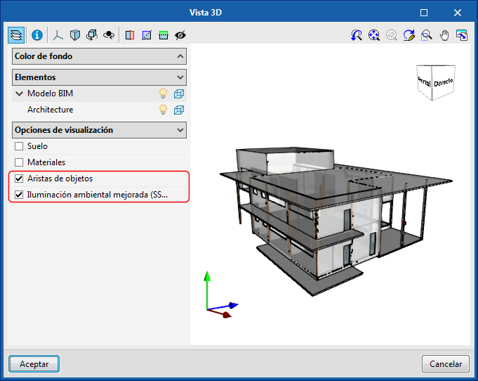
Object edges and improved ambient lighting in 3D views
The options "Object edges" and "Improved environment lighting" have been implemented in the 3D views where the BIM model is represented. Using these options, the appearance of the 3D view changes.
Open BIM FUJITSU
Control diagram and cabling diagram
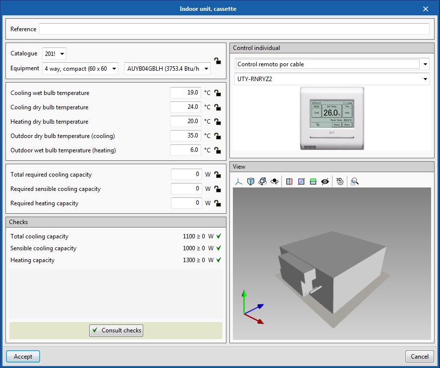
As of the 2020.b version, users can, in "Open BIM FUJITSU", select both the individual control of the indoor units and the centralized control of the system.
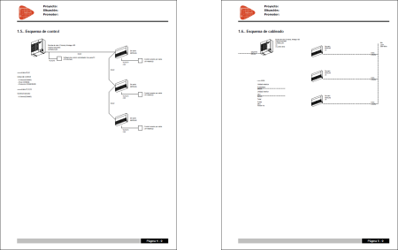
A control diagram and cabling diagram are generated automatically in the design report.
The control diagram shows the type of communication cable the equipment requires with the control devices and their references, in accordance with the nomenclature of the manufacturer.
The cabling diagram shows the type of power supply cable the air conditioning equipment requires: current of the machines, cable section and phase type.
Open BIM MOVAIR
“Move end” tool
In the 2020.b version of Open BIM MOVAIR, the "Move end" tool has been implemented. Using this tool, users can change the position of one of the ends of a straight duct. The new position of the end can snap to the end of another duct or the extension of the axis of the duct whose end is being moved.
Open BIM ROTH
Catalogue for France
Since previous versions, "Open BIM ROTH" can be installed in Catalan, English, Portuguese and Spanish. In all these cases, the ROTH products catalogue that is used in the program for the design of air conditioning systems with radiant floor systems, is that used by the manufacturer to distribute in Spain.
As of version 2020.b, the "Open BIM ROTH" program can also be installed in French and, in this case, the products catalogue used in the program is that used by ROTH to distribute in France.
Open BIM TOSHIBA
Calculation of the maximum refrigerant limit
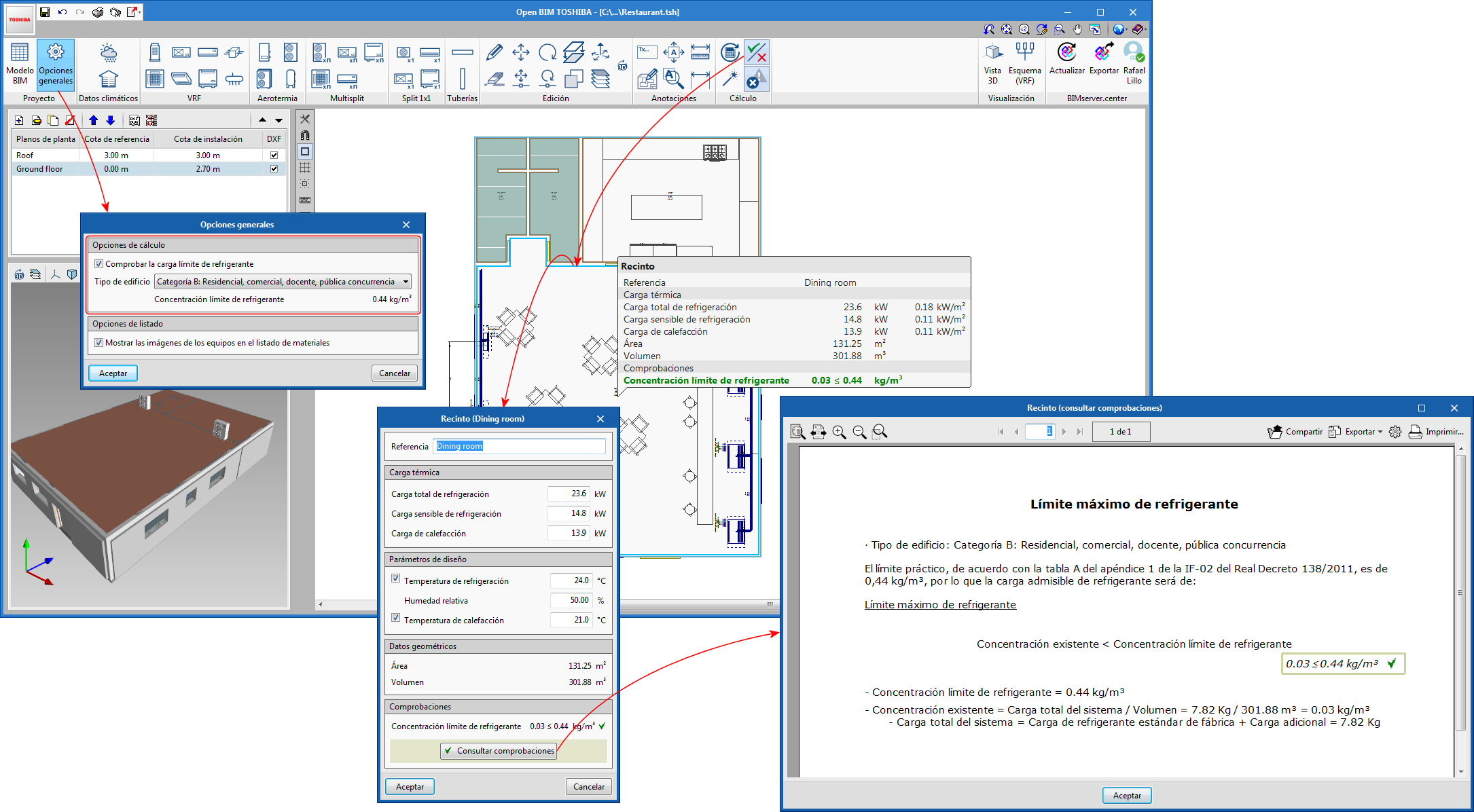
As of the 2020.b version of "Open BIM TOSHIBA", the program calculates the concentration level of the coolant of the VRF systems of each space, which can be compared with the maximum allowable limit established by Royal Decree 138/2011.
In the "General options" panel, users select the type of building. For categories A and B, the limit is 0.44 kg/m3, and for categories C and D, there is no limit.
The checks are carried out on all spaces that contain one or more VRF indoor units. Using the "Consult results and checks" button of the toolbar, users can access the detailed calculation for each space.
Code implementation and improvements in its application
Concrete structures
EUROCODE 2 MS EN 1992-1-1:2010 (Malaysia)
“Malaysia national annex to EUROCODE 2: Design of concrete structures - Part 1-1: General rules and rules for buildings”.
Implemented in:
- CYPECAD
- CYPE 3D
- Embedded retaining walls
- Reinforced concrete cantilever walls
- Foundation elements
- Box culverts
EUROCODE 2 SS EN 1992-1-1:2008 (Singapore)
“Singapore national annex to EUROCODE 2: Design of concrete structures - Part 1-1: General rules and rules for buildings”.
Implemented in:
- CYPECAD
- CYPE 3D
- Embedded retaining walls
- Reinforced concrete cantilever walls
- Foundation elements
- Box culverts
Loads on structures. Earthquake loads
EUROCODE 8 MS EN 1998-1 (2015) (Malaysia)
“Malaysia national annex to EUROCODE 8: Design of structures for earthquake resistance - Part 1: General rules, seismic actions and rules for buildings”.
Implemented in CYPECAD and CYPE 3D.
EUROCODE 8 SS EN 1998-1 (2013) (Singapore)
“Singapore national annex to EUROCODE 8: Design of structures for earthquake resistance - Part 1: General rules, seismic actions and rules for buildings”.
Implemented in CYPECAD and CYPE 3D.
CYPECAD
Edit bolts to baseplate connection system (by baseplate)
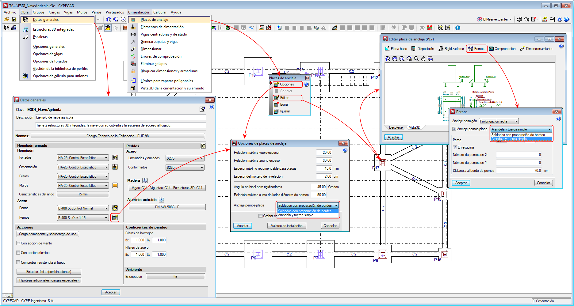
Users can now edit the bolt to baseplate connection method for each baseplate.
Up until the 2020.a version, only one connection system could be selected for all the project (Project > General data).
As of the 2020.b version, when users edit an individual baseplate (Foundations > Baseplates > Edit), they can change the connection system between the bolts and the baseplate (“Bolts” button > “Bolts-baseplate anchorage” option).
In the 2020.b version, users can also define the connection system between bolts and the general baseplate of the project from “Foundations” > “Baseplates” > “Options”.
Floor plans with shear wall tags
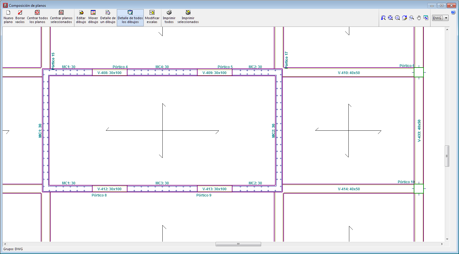
In the 2020.b version of CYPECAD, tags of shear walls that have been defined by users can now be represented on floor plan drawings.
CYPECAD, CYPE 3D, Embedded retaining walls, Reinforced concrete cantilever walls, Foundation elements and Box culverts
Code implementation
In the 2020.b version of CYPE programs, two concrete structure codes have been implemented as well as their corresponding seismic action codes:
- EUROCODE 2 MS EN 1992-1-1:2010 and EUROCODE 8 MS EN 1998-1 (2015) (Malaysia)
- EUROCODE 2 SS EN 1992-1-1:2008 and EUROCODE 8 SS EN 1998-1 (2013) (Singapore)
More information can be found in the “Code implementation and improvements in its application” section.
CYPECAD MEP
Export installations to the BIM project
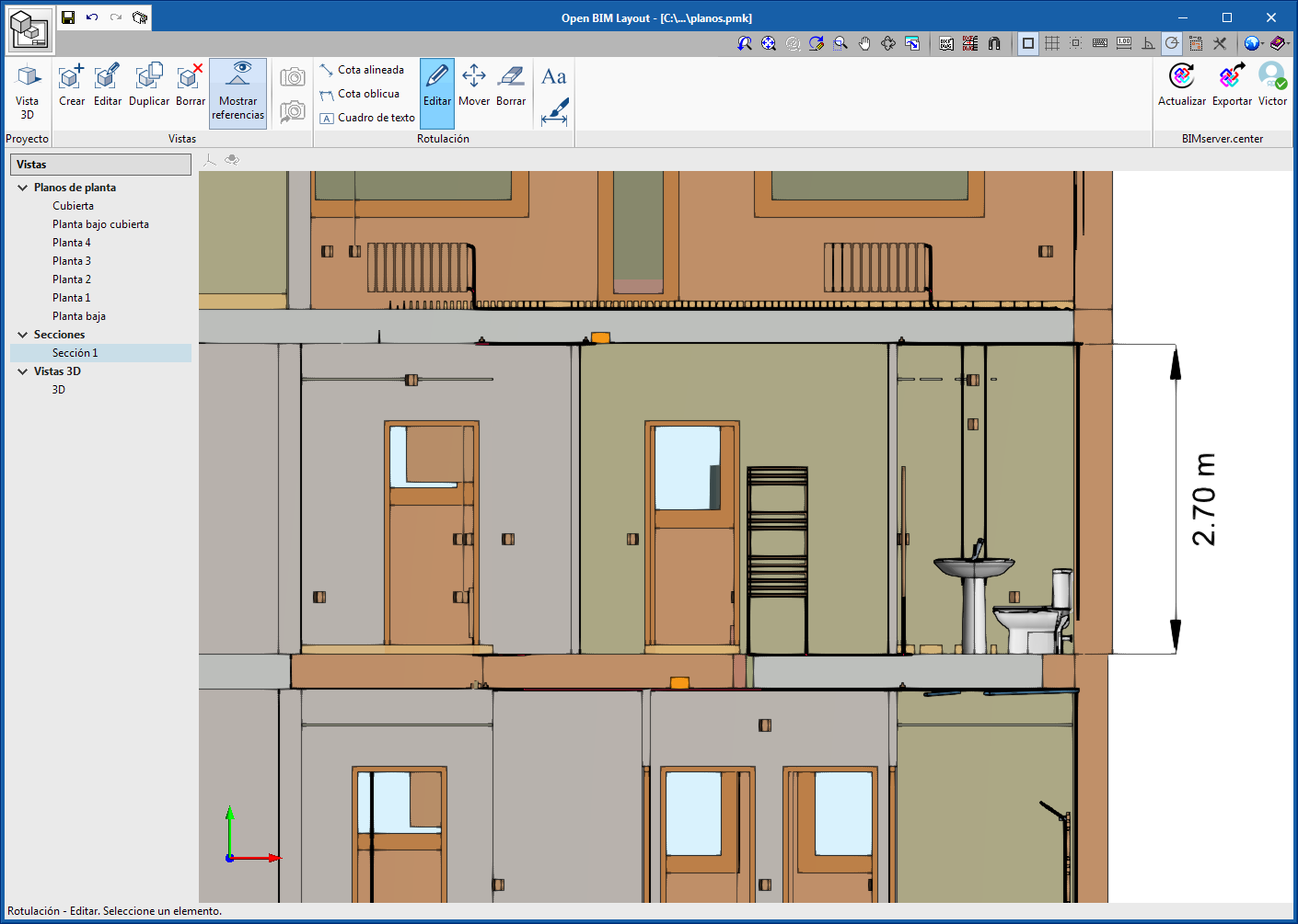
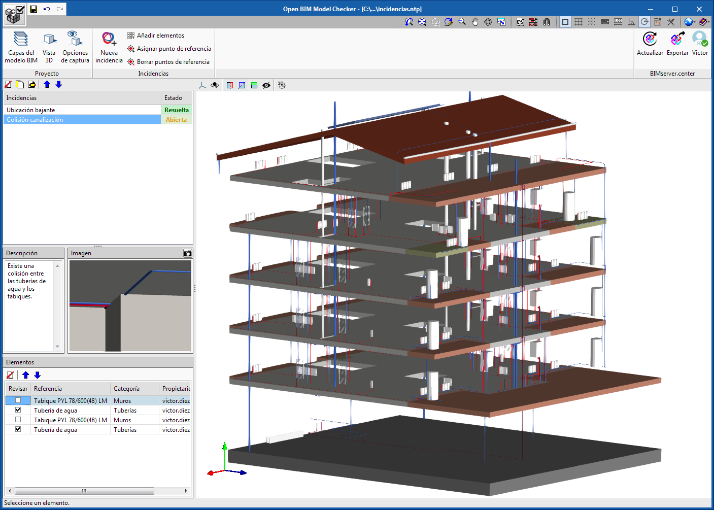
As of the 2020.b version, CYPECAD MEP can generate an IFC file containing the installations that have been introduced in the project, as well as the construction elements it has contained until now. This way, the installation that have been introduced in CYPECAD MEP can be integrated into a BIMserver.center project, and this information can be interpreted by other BIM applications such as "Open BIM Layout" and "Open BIM Model Checker", which are available from the BIMserver.center “Store”.
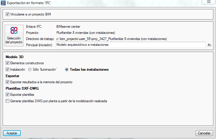
Users can indicate the entities of the model to be added to the file in the “3D Model” menu, in the “Export to IFC” format panel of CYPECAD MEP:
- Construction elements (implemented in previous versions)
The export file will include the architectural elements that have been defined in the project such as façades, partitions, floor slabs, roofs... - Installations (new as of the 2020.b version)
The export file will include the elements of the installations that have been defined in each tab of the program (thermal analysis, acoustic analysis, fire, sanitation...). Users can choose to only export the elements of the active tab or all the installations.
Open BIM Stairs & Ramps – Open BIM Vertical Connections
Lifts
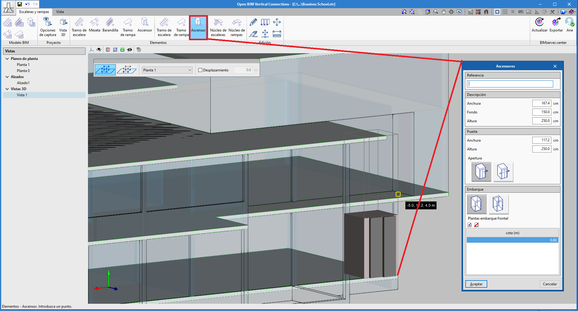
As of the 2020.b version, lifts can be introduced in "Open BIM Stairs & Ramps". Due to this, the name of the program has been changed to "Open BIM Vertical Connections".
As occurs with all the elements that have been introduced in "Open BIM Vertical Connections", lifts can be exported to the BIM project that is located on the BIMserver.center platform to which the project is connected, and information can be exchanged with other specialist programs that may be involved in the same project.
The lifts that are introduced can be configured. Users can modify the size of the cabin, the stops or the type of opening.
Lift animation
"Open BIM Vertical Connections" generates an animated image of the lifts that have been introduced in the program, which is also exported to the BIM project so that it can be viewed in the 3D viewer of the BIMserver.center platform or from any of the applications that are involved in the project.
Open BIM Model Checker
Automatic recognition of the owners of elements with incidents
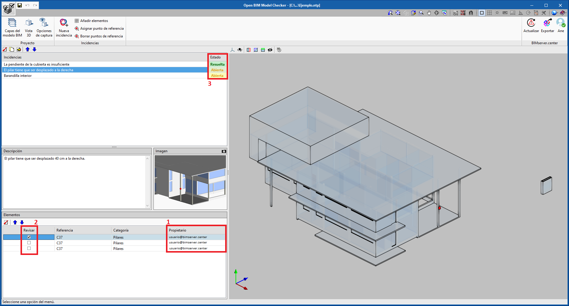
When an element is assigned to an incident, "Open BIM Model Checker" automatically detects the owner of the element and indicates it in the table of elements of the incident ("Owner" column).
This way, "Open BIM Model Checker" users will be able to know whom to contact in case the affected element is to be modified (reference "1" in the image).
Selection of elements with incidents to communicate to the owner
Several elements can be assigned to the same incident, but not all of them may have to be modified. Therefore, not all the owners of these elements have to receive notifications of the incident. The "Review" column has been included in the table of elements of an incident (in addition to the "Owner" column indicated in the previous section), so users can activate the elements together with their respective owners to whom the incident must be addressed (reference "2" in the image).
Incident status
In the 2020.b version of "Open BIM Model Checker", the status of the incidents has also been implemented (reference "3" in the image). Program users can mark each incident as “Solved" or "Open". This way, the incidents that have been introduced can be controlled more effectively.
CYPELEC Electrical Mechanisms
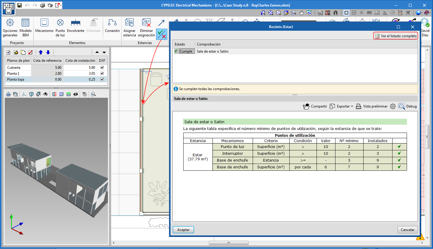
Prescriptions for Points of use
As of the 2020.b version, the program performs checks related to the number of Points of use in the spaces of buildings. To do so, a set of tools, called “Rooms”, has been created. Three steps have been established to achieve this task:
- Define the minimum number of points of use per room
- Manual or automatic assignment of the rooms
- Check reports
Define the minimum number of points of use per room
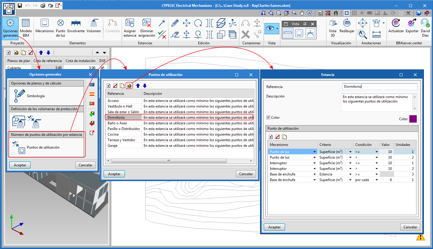
In the "General settings" button of the toolbar, (Project section), a new tool to define the "Number of points of use per room" is included. The points of use or minimum mechanisms required can be established for each room. These minimum values can be defined by three criteria: by surface, by length or for the room as a whole.
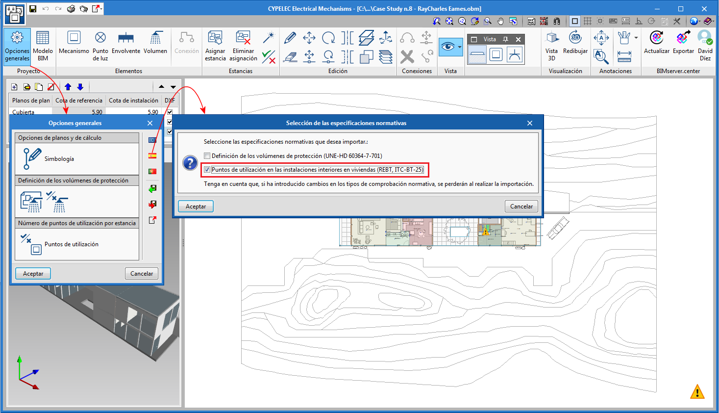
Rooms can be defined automatically by selecting the corresponding code. If “Spain” is selected, the rooms defined in the ITC-BT-25 of the REBT can be uploaded.
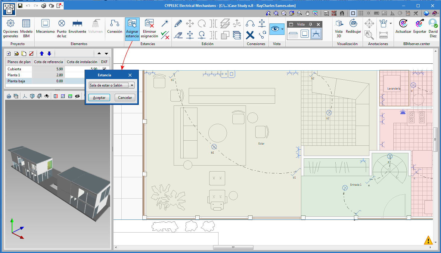
Manual or automatic assignment of the rooms
The assignment of the spaces that are imported from the architectural model can be carried out in two ways:
- Manually
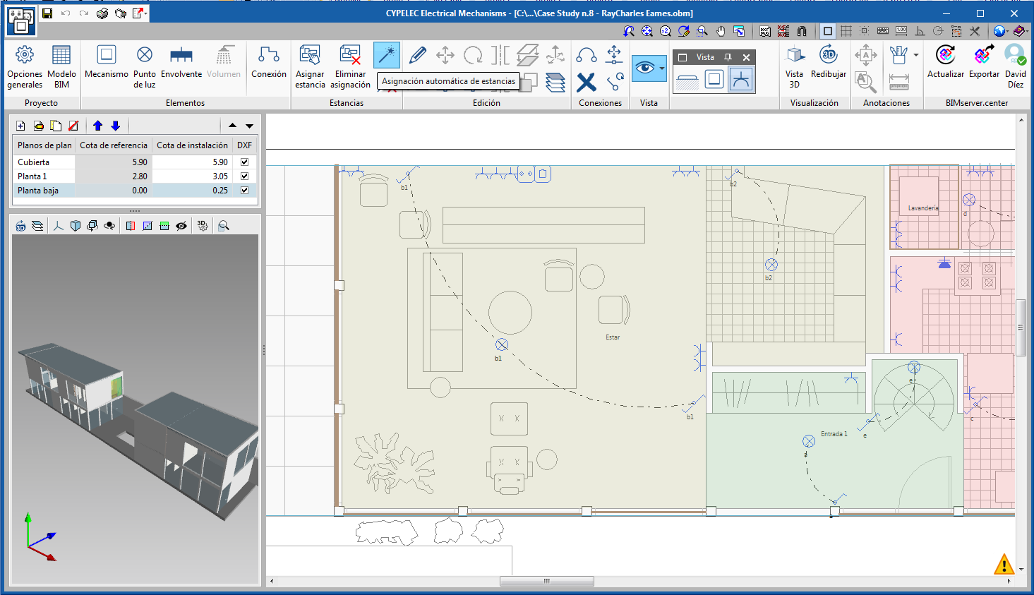
Users select each space of the building to assign the corresponding room. To do so, they must press the “Assign space” button. - Automatically
The “Automatic room assignment” button must be used. In this case, the program analyses the spaces and assigns the room if possible.
Check reports
Using the “Consult checks" button and having selected a room, the program displays a check report containing the points of use defined for that stay and the compliance of their criteria. Users can obtain a complete check report for other rooms from the same dialogue box.
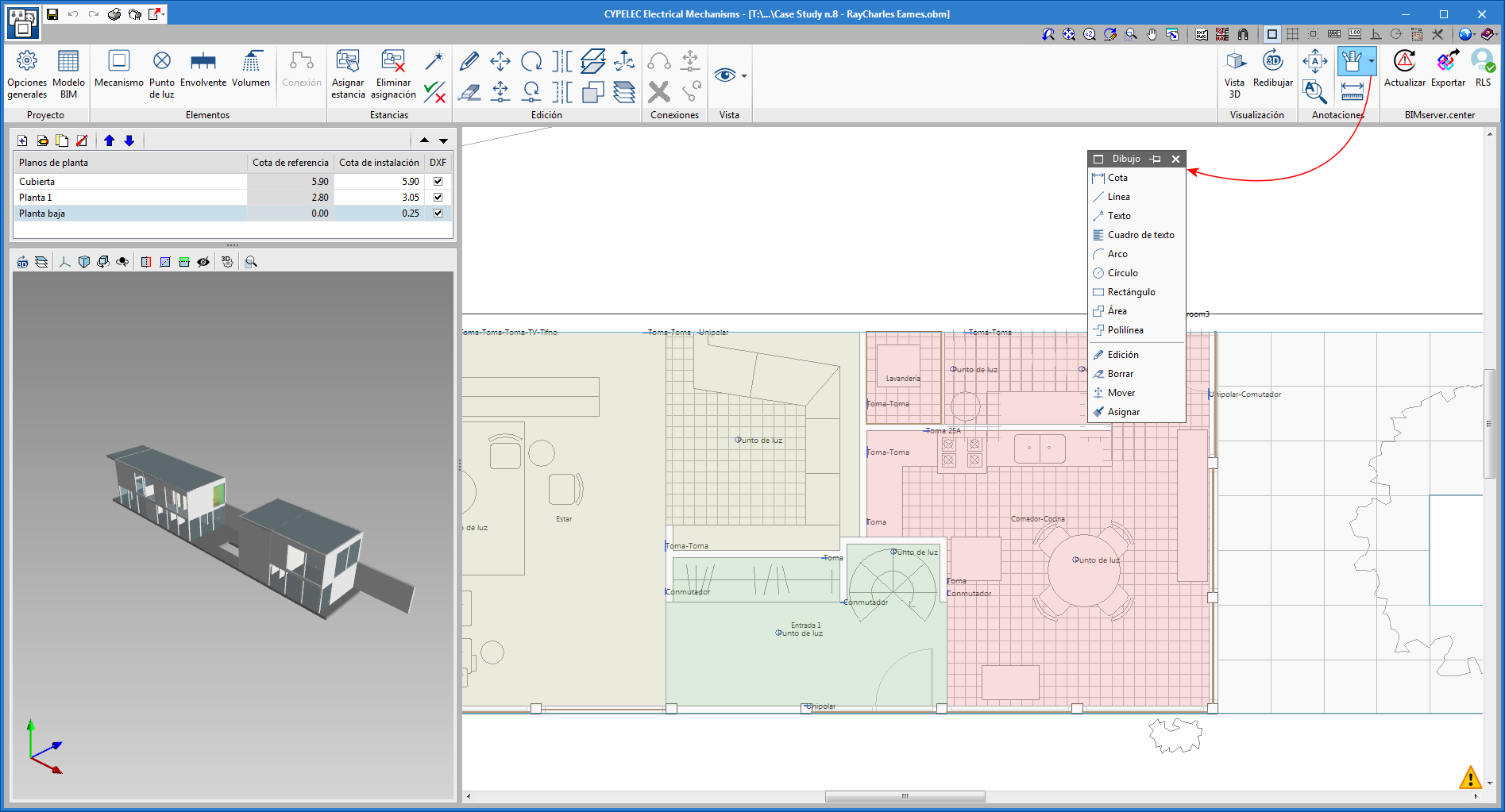
Drawing tool. Complete and add tags
The “Drawing” tool has been added in the “Notes” section of the toolbar. The “Drawing” tool contains options that were available previously and new ones. With them, users can create their own tags and edit those that have already been introduced.
CYPELEC Networks
Phase names in a three-phase system
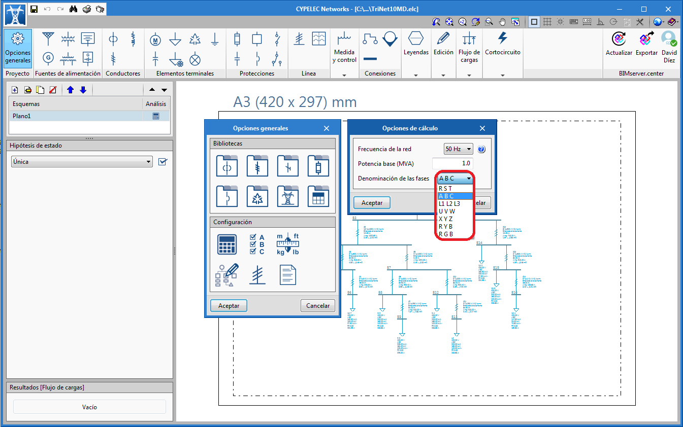
The 2020.b version of “CYPELEC Networks” contains new ways to identify and distinguish the three phases of a three-phase electrical system.
CYPEPLUMBING Water Systems
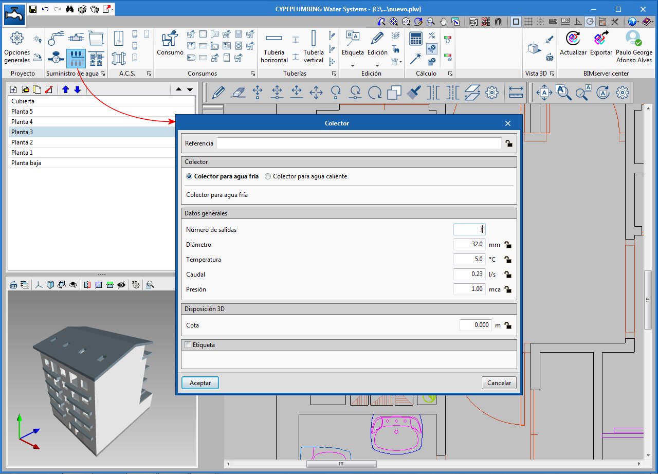
Introduce manifolds
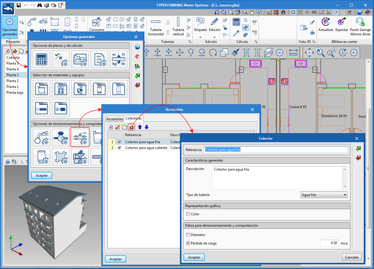
The 2020.b version allows users to use manifolds. Manifolds are accessories that have a water inlet and several outlets.
As occurs with other accessories, for user to be able to use manifolds in the program, they have to define them first in “General options” > “Accessories” (predefined manifolds already exists in the predefined configurations for Spain and Portugal).
To introduce them in the installation, the “Manifold” button has been added to the “Water supply” section of the toolbar.
CYPEPLUMBING Water Systems, CYPEPLUMBING Solar Systems and CYPEHVAC Hydronics
New vertical pipe editing
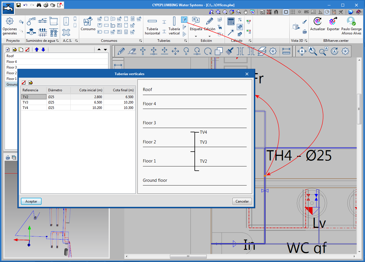
The “Edit” tool has been included in the “Pipes” section of the toolbar (for vertical pipes), with which users can view and edit, in a single window, all the spans of the vertical pipe they select.
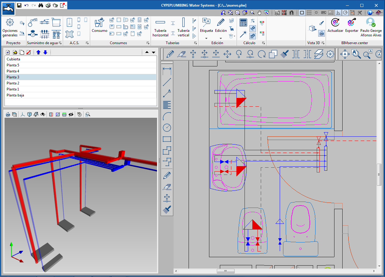
Automatic detection of the flow direction
When users introduce vertical pipes, the program automatically tags the initial and final elevation of the direction of flow of the liquid they are carrying (unless these elevations are blocked).
CYPEPLUMBING Sanitary Systems
Accessory properties (cleanouts, air vents, water seals)
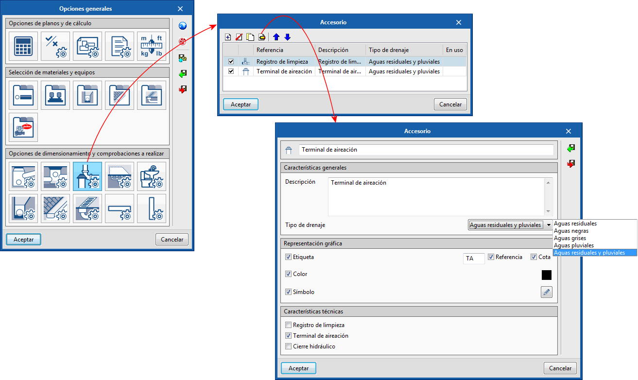
"Cleanouts" and "Air vents" could already be introduced in previous versions, but users could not customize their symbols or their reference, nor define their type of drainage (foul water, rainwater, grey water...).
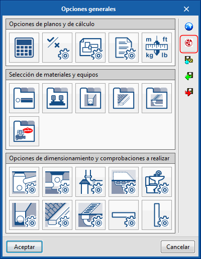
As of the 2020.b version, the "Accessory" icon has been included in the "Design and check options to be carried out" section of the "General options" panel. By selecting this icon, users can define the properties of cleanouts, air vents, water seals.
Furthermore, the "Accessories" section has been included in the toolbar, which contains the icons to introduce the accessories that have been defined in "General Options", in the network.
CYPEPLUMBING Sanitary Systems and CYPEPLUMBING Water Systems
Code selection
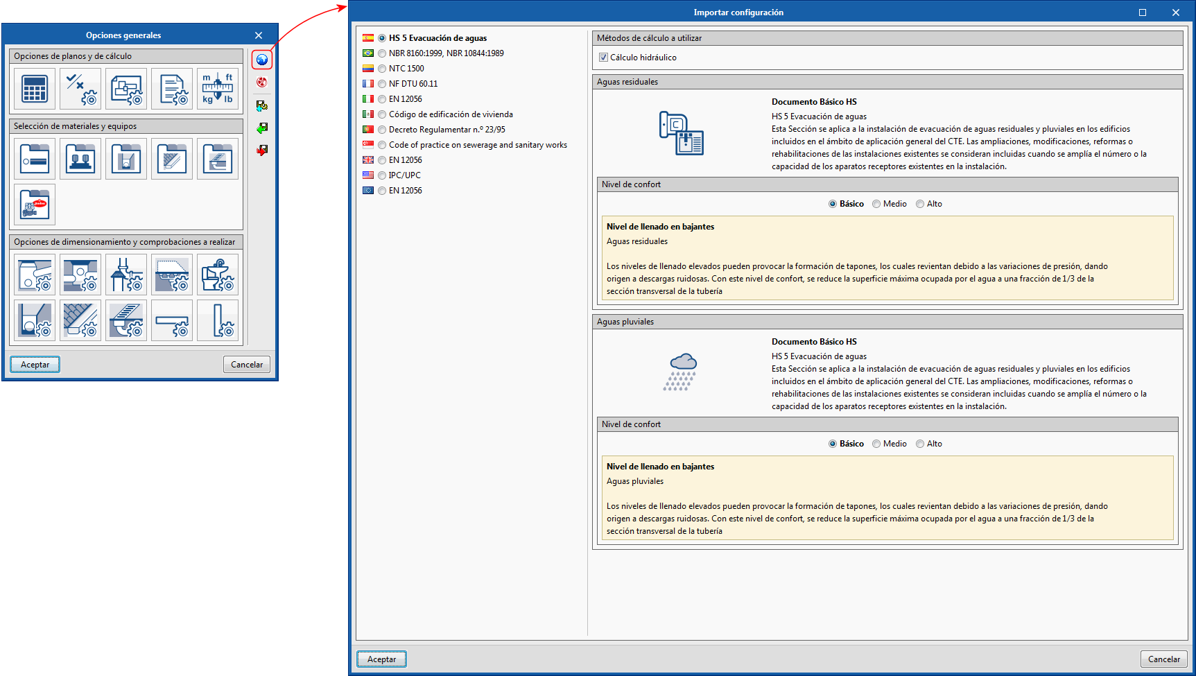
In previous versions, users selected the design code to be used in "CYPEPLUMBING Sanitary Systems" and "CYPEPLUMBING Water Systems" by selecting the flag of the country of the code to be applied, which appeared on the side of the "General Options" panel. Now, a globe icon has been included in the panel, which when pressed, opens another panel where users can select the flag of the country of application, and the selectable parameters of the chosen design code.
CYPEHVAC Ductwork
Design of air treatment units (ATUs)
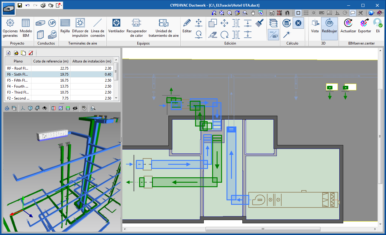
As of the 202.b version, users can introduce Air Treatment Units together with the duct network in “CYPEHVAC Ductwork”. The design of the ATUs is carried out in the same way as was done in CYPEHVAC Schematics (by introducing the thermal loads and air flows manually).
The introduction of ATUs in CYPEHVAC Ductwork has the following advantages:
- There is a physical representation of the equipment in the space, and these are integrated with the air ducts.
- For primary air conditioners, the air flows do not have to be introduced manually, because the program reads them from the duct installation that is connected to this equipment.
Air treatment units can still be introduced in “CYPEHVAC Schematics” to obtain the diagram of the installation. However, the design process that, until this version, was performed in “CYPEHVAC Schematics” is now done in “CYPEHVAC Ductwork”.
CYPETHERM EPlus
Import equipment from Open BIM VAILLANT
As of the 202.b version, VAILLANT aerothermal equipment and fan coils that have been defined in “Open BIM VAILLANT” can be imported directly in “CYPETHERM EPlus” with the Open BIM connection using the IFC standard. Additionally, if this equipment is associated with a “CYPEHVAC Hydronics” project (design of water distribution installations for air conditioning), which is connected to the same Open BIM project, “CYPETHERM EPlus” also imports the connections between them.
Return to the 2020 version download area
Tel. USA (+1) 202 569 8902 // UK (+44) 20 3608 1448 // Spain (+34) 965 922 550 - Fax (+34) 965 124 950