
- New modules and programs
- BIMserver.center
- Code implementation and improvements in its application
- CYPECAD
- CYPEPLUMBING Sanitary Systems
- CYPEPLUMBING Water Systems
- AcoubatBIM by CYPE
- CYPEFIRE Sprinklers
- CYPEFIRE Design
- CYPETHERM programs with EnergyPlus analysis motor (CYPETHERM EPlus, CYPETHERM HE Plus and CYPETHERM RECS Plus)
- CYPETHERM HVAC
- Adjacent elements in the thermal and acoustic programs
- Return to the 2018 version download area
New modules and programs
CYPETEL Wireless
CYPETEL Wireless is an application for the design of indoor wireless networks by carrying out coverage analyses.
CYPETEL Wireless is integrated in the Open BIM workflow using IFC format interchange files. CYPETEL Wireless is distributed for free and can be downloaded from the BIMserver.center® platform website.
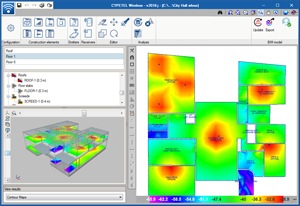
The program allows users to visualise results on-plan and in 3D views using contour lines and maps. CYPETEL Wireless generates reports containing the results obtained in the installations. These reports can be exported to several formats (TXT, HTML, RTF, DOCX, PDF) for them to be printed and/or modified by users. It also generates diagrams and drawings that can be exported to various formats (DXF, DWG, JPG, EMF, BMP).
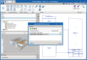
CYPETEL Wireless requires an architectural model of the building in IFC format generated by CAD/BIM programs, such as IFC Builder (free CYPE tool designed to create and maintain IFC building models), Allplan®, Archicad®, Revit®... CYPETEL Wireless gathers, in addition to the spaces of the building, the construction elements and positions of the electrical outlets that the specialist programs have generated in the Open BIM workflow. Users can view equipment included in other disciplines such as HVAC, Lighting, Electricity, etc. in the 3D view.
CYPETEL Wireless exports an IFC file with the position of the emitters so they can be viewed by other Open BIM workflow programs. It also has an associated PDF file with the results that have been obtained. This way, the BIM model of the project is updated and the Open BIM workflow is consolidated.
More information will soon be available on the “CYPETEL Wireless” webpage.
CYPELEC Core
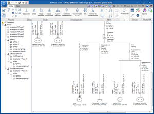
CYPELEC Core is a program for the design of low-voltage electrical installations that incorporates the analysis motor of CYPELEC REBT. Users can draw single-line diagrams of the installation and configure the properties of the elements it contains.
It has the same main functionalities of CYPELEC REBT for the load flow and short circuit design, allowing users to edit all the elements with no restrictions on the power or number of lines. Its results output allows users to obtain drawings of the single-line diagram, justification reports, quantity and results tables.
The design checks carried out in the program are based on the specifications of the international IEC standards.
This application is integrated in the Open BIM workflow using the IFC standard, and so maintains the interaction with the rest of the tools.
CYPELEC Core is a free application and can be downloaded exclusively from the BIMserver.center® platform. Its first version can be installed in Spanish or Catalan. It will be available in more languages in upcoming versions.
More information available soon.
BIMserver.center
Download CYPE programs from the BIMserver.center platform
The following CYPE programs can be downloaded exclusively from the BIMserver.center® platform:
- CYPETEL Wireless
- CYPELEC CORE
Code implementation and improvements in its application
Concrete structures
NTC: 2017 (Mexico D.F.)
Normas Técnicas Complementarias. Diseño y Construcción de Estructuras de Concreto (2017).
Implemented in CYPECAD, CYPE 3D and StruBIM Deep Beams.
Concrete block structures
NTC: 2017 (Mexico D.F.)
Normas Técnicas Complementarias. Diseño y Construcción de Estructuras de Mampostería (2017).
Implemented in CYPECAD.
Loads on structures. Wind loads
NTC: 2017 (Mexico D.F.)
Normas Técnicas Complementarias. Diseño por Viento (2017).
Implemented in CYPECAD.
Loads on structures. Earthquake loads
NTC:2017 (Mexico D.F.)
Normas Técnicas Complementarias. Diseño por Sismo (2017).
Implemented in CYPECAD and CYPE 3D.
Water supply
EN 806-3 (EU)
Especificaciones para instalaciones de conducción de agua destinada al consumo humano en el interior del edificio. Parte 3: Dimensionamiento de tuberías.
Implemented in CYPEPLUMBING Water Systems.
CYPECAD
Selection of BIM model files to import
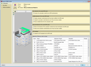
During the creation and updating processes of a project using a BIM model, users can select the IFC files of the BIM model that are to be imported. Until now, all the IFC files were read, now users decide which. This way, the updating process of the BIM model is quicker, since the IFCs that are not required in CYPECAD are not imported. Users can at any moment update the project and import all the IFC files of specialist programs of the BIM model.
CYPEPLUMBING Sanitary Systems
Document configuration
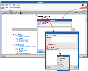
The Project documents manager, which was implemented in the previous program version (2018.i), allows users to generate a document, with its index, which includes reports selected by users.
As of the 2018.j version, the manager allows users to configure several documents of the same project with different contents (e.g. a document for wastewater and another for rainwater, one that includes quantities and another that does not). This way, users do not have to change the contents of the document to generate more than one type, and can configure a collection of documents with the required contents.
CYPEPLUMBING Water Systems
Implementation of the EN 806-3 code (EU)
Implemented in the 2018.j version are the design criteria established in the EN 806-3 code (Specifications for installations inside buildings conveying water for human consumption. Part 3: Pipe sizing).
Document configuration
The Project documents manager, which was implemented in the previous program version (2018.i), allows users to generate a document, with its index, which includes reports selected by users.
As of the 2018.j version, the manager allows users to configure several documents of the same project with different contents (e.g. a document that includes quantities and another that does not). This way, users do not have to change the contents of the document to generate more than one type, and can configure a collection of documents with the required contents.
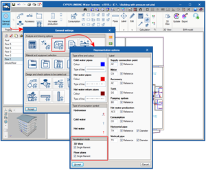
Single filament and volumetric views in drawings, and 2D and 3D views
The 2018.j version of CYPEPLUMBING Water Systems includes two visualisation modes that affect the 2D and 3D views of the installation. For this, the “Visualisation mode” section has been added to the “Representation options” panel (General settings > Analysis and drawing options > Representation options). This section allows users to activate or deactivate the “Single filament” option for the 2D and 3D views separately. When activated, a single filament view is displayed, and when deactivated, a volumetric view can be seen. The properties of these views are detailed below:
- Single filament
view This is the view that was available as of previous versions and that which is active by default. With this view, the pipes of the installation a represented as a line on drawings, and in the 2D and 3D on-screen views. - Volumetric view
The pipes of the installation are represented in their real magnitude on drawings and in the 2D and 3D views.
In the 3D views, the remaining elements of the installation do not vary when either view is selected, and are represented with a volume surrounding their real appearance. In the 2D views, pressure sets, tanks and hot water production equipment are represented with their symbols in the “Single filament visualisation” (which may or may not coincide with their real appearance). In the “Volumetric view”, these elements are represented with their symbols and also with their real outline.
When the pipes are exported to the BIM model, these are exported as single filament elements, if the single filament option of the 3D view is activated or as volumetric elements if it is not.
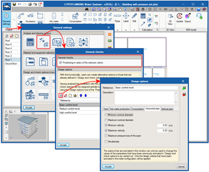
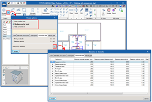
Design options and checks
Users can now add a series of complementary checks that modify and complement the design and check options of the selected code.
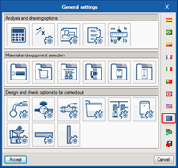
Since its first version, the design and check options of the selected code are defined in the “Design and check options to be carried out” section of the “General settings” dialogue box. In the 2018.j version, the “General checks” button has been added to the “Analysis and drawing options” section of the “General settings” dialogue box, which opens a panel of the same name, in which users can configure more design and check options:
- General checks
- Positioning in series of the wetroom valves
By activating this option, users can check that these valves are not connected in series.
- Positioning in series of the wetroom valves
- Design options
In this section of the “General checks” section, users can create alternative options to those that are already defined in “Design and check options to be carried out”. It is possible to configure several design option groups. Once defined, they are not applied to the design of the installation until users assign them using the “Design options” button of the “Project” section of the top tool menu.
AcoubatBIM by CYPE
Installation in Spanish, Portuguese and Italian
In previous versions, AcoubatBIM by CYPE could only be installed in English and French. As of the 2018.j version, AcoubatBIM by CYPE can also be installed in Spanish, Italian and Portuguese.
CYPEFIRE Sprinklers
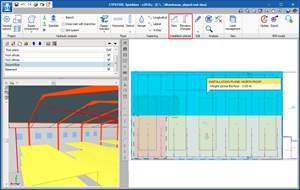
Reference drawings of the installation
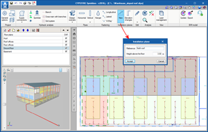
The 2018.j version of CYPEFIRE Sprinklers contains two tools that allow users to define sprinkler installations with different installation planes, horizontal and sloped (such as sprinkler systems parallel to sloped roofs) more quickly and comfortably.
To do so, two new options have been included (“New” and “Elevation changes”) in a new section of the top tool menu (Installation planes):
- New
Allows users to quickly define a reference plane of the installation by introducing its outline, a reference and a height above the level of the floor that is currently being viewed. Users can define as many planes as they wish.
Sprinklers and pipes that are to be placed in one of the planes that has been defined, must have the “Place the element in the reference plane of the installation” option marked (a new option of the panel that opens when a pipe or sprinkler is introduced) and then position them in the desired plane.
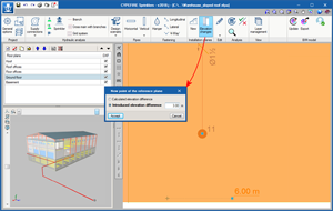
- Elevation changes
Using this option, users can define sloped reference planes. A horizontal reference plane must first be defined using the previous option. Then, using the “Elevation changes” option, three points are to be marked on the reference plane, indicating their elevation, which will define the corresponding sloped plane.
CYPEFIRE Design
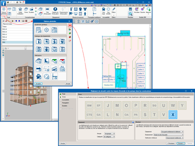
New types of ERP projects: W, X, Y, PA, CTS, SG, OA, PS, GA, EF and BM
The 2018.j version of CYPEFIRE Design includes the following types of ERP building projects (Établissements recevant du public) for the Moroccan code, “Règlement de sécurité contre les risques d’incendie et de panique dans les constructions”:
- Établissements recevant du public: Administration, banques, bureaux (Type W)
- Établissements recevant du public: Établissements sportifs couverts (Type X)
- Établissements recevant du public: Musées (Type Y)
- Établissements recevant du public: Établissements de plein air (Type PA)
- Établissements recevant du public: Chapiteaux, tentes et structures itinérants effectif > 50 personnes (Type CTS)
- Établissements recevant du public: Structures Gonflables (Type SG)
- Établissements recevant du public: Hôtels-Restaurants d’altitude (Type OA)
- Établissements recevant du public: Parcs de stationnements couverts (Type PS)
- Établissements recevant du public: Gares accessibles au public (Type GA)
- Établissements recevant du public: Établissements flottants (Type EF)
- Établissements recevant du public: Bains maures (Type BM)
CYPETHERM programs with EnergyPlusTM analysis motor (CYPETHERM EPlus, CYPETHERM HE Plus and CYPETHERM RECS Plus)
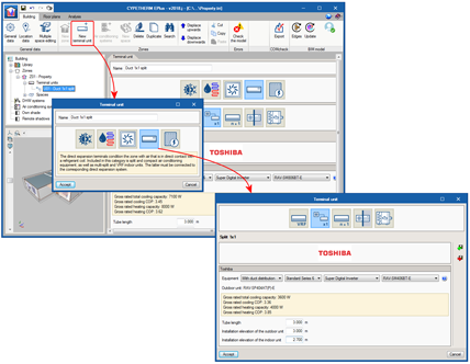
TOSHIBA duct 1x1 split equipment
As of the 2018.j version, TOSHIBA duct 1x1 split equipment can be simulated in the program. As occurs with existing split 1x1 systems (wall and floor), duct systems are defined as terminal units within each zone.
To add TOSHIBA duct 1x1 split equipment, a new terminal unit must be added, then select the “Direct expansion” category, where the Split 1x1 button appears. In the panel that is shown when this button is clicked on, users can choose amongst different TOSHIBA wall and floor duct split models.
When a duct 1x1 split model is chosen, users must define the length of the refrigerant pipe, the installation levels of the outdoor and indoor units. These parameters are used to calculate the associated power loss.
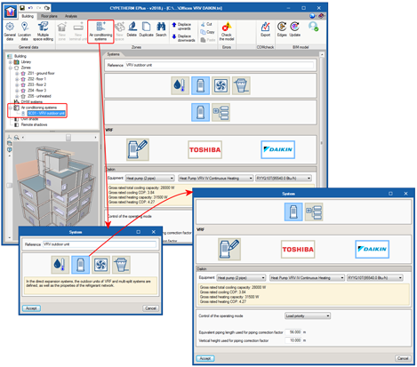
Daikin variable refrigerant volume (VRV) systems
The catalogue of Daikin VRV equipment has been integrated in CYPETHERM programs that have the EnergyPlus™ motor (CYPETHERM HE Plus, CYPETHERM RECS Plus and CYPETHERM EPlus). This way, the number of manufacturers amongst which users can choose variable refrigerant flow (VRF) systems is increased.
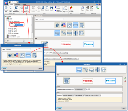
The Daikin logo has been added in Direct Expansion Air Conditioning Systems, in the VRF button. By clicking on it, users can choose amongst the different Daikin air-condensed VRV outdoor unit series and models, which are completely defined in the program. Similarly, Daikin indoor VRV units can be added using the New Terminal Unit button, Direct Expansion type, VRF button.
It is not possible to combine indoor and outdoor VRF systems of different manufacturers, nor manufacturer models with generic models.
Import TOSHIBA multi-split and 1x1 split equipment from the BIM model
CYPETHERM programs with the EnergyPlusTM motor (CYPETHERM HE Plus, CYPETHERM RECS Plus and CYPETHERM EPlus) can import TOSHIBA Multi-split and 1x1 Split equipment from an IFC file that has been generated and included in the BIM model by CYPETHERM HVAC.
CYPETHERM HVAC
Horizontal duct elevations
In previous versions, the elevation of the horizontal ducts and connections was not specified and corresponded to the elevation of the installation that was defined at that floor.
As of the 2018.j version, users can indicate the elevation of the horizontal duct when it is being introduced. By default, this elevation is the elevation of the installation defined at that floor.
The connections between ducts that the program generates take the elevation of the duct. This elevation can be modified by editing the connections, so users can modify it if they also modify the elevation of the horizontal duct.
Now, it is possible to design an installation with elevation changes at the same floor. To do so, users must introduce a vertical duct of the same length as the elevation difference that has been generated.
Adjacent spaces in thermal and acoustic programs
When CYPE thermal and acoustic programs import an IFC file that does not contain information on adjacent spaces, they analyse the file and the layout of the spaces to detect what type of spaces are adjacent to them.
As of previous versions, these adjacent spaces were included automatically in the IFC files that are generated by IFC Builder (free CYPE application designed for the creation and maintenance of IFC building models), as this program generates them. Other CAD/BIM programs (such as Allplan®, Archicad®, Revit®...) do not export this information to IFC files, hence, if one of these programs was being used as the initial tool of the BIM model, the boundaries had to be defined by users in each specialised acoustic and thermal application.
With this important new feature of the 2018.j version, information on adjacent spaces is included in CYPE thermal and acoustic programs, regardless of which CAD/BIM program is used as the geometric modeller of the Open BIM project.
Below is a list displaying the thermal and acoustic programs CYPE has available that benefit from this new feature:
- Acoustic
- CYPESOUND (EU International)
- CYPESOUND CTE (Spain)
- CYPESOUND NRA (France)
- CYPESOUND DRAPDE (Italy)
- CYPESOUND RRAE (Portugal)
- AcoubatBIM by CYPE (International)
- Thermal
- CYPETHERM HE Plus (Spain)
- CYPETHERM EPlus (International)
- CYPETHERM LOADS (International)
- CYPETHERM RT2012 (France)
- CYPETHERM RTExistant (France)
- CYPETHERM COMETH (France)
- CYPETHERM RT2012 CNOA (France)
- CYPETHERM RECS Plus (Portugal)
- CYPETHERM REH (Portugal)
- CYPETHERM C.E. (Italy)
Return to the 2018 version download area
Tel. USA (+1) 202 569 8902 // UK (+44) 20 3608 1448 // Spain (+34) 965 922 550 - Fax (+34) 965 124 950