- BIMserver.center
- Code implementation and improvements in its application
- CYPECAD
- CYPEPLUMBING Sanitary Systems
- CYPEPLUMBING Water Systems
- CYPELUX
- CYPESOUND, CYPESOUND CTE, CYPESOUND RRAE and CYPESOUND DRAPDE
- AcoubatBIM by CYPE
- Intermediate results in reports
- Calculation of the sound pressure level generated by building equipment
- Import sound sources from the BIM model
- New parameters for the advanced search of the database
- Update of the acoustic requirements defined in the program for the French (NF NRA 2000) and Italian (D.P.C.M. 5 dicembre 1997) codes
- Portuguese sound code RRAE
- CYPEFIRE Sprinklers
- CYPEFIRE Design
- CYPETHERM Improvements
- CYPETHERM EPlus, CYPETHERM HE Plus and CYPETHERM RECS Plus
- TOSHIBA 1x1 split equipment
- DAIKIN Altherma aerothermal systems
- Update to version 8.8 of the analysis engine of EnergyPlus™
- Definition of the demand of the total domestic hot water of the building
- New interface for the definition of air conditioning systems
- Definition of multiple water air conditioning systems in the same project
- CYPETHERM HVAC
- Return to the 2018 version download area
New modules and programs
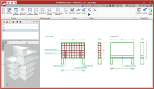
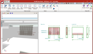
StruBIM Deep Beams
StruBIM Deep Beams is a tool for the design of deep beams. This application is integrated in the Open BIM workflow using the IFC standard.
- Import from the BIM model
Users can import beams with this applications by using an assistant with which they can filter which beams are to be imported by applying a depth/length ratio criteria.
StruBIM Deep Beams imports the geometry of the beams that meet the depth/length ratio that has been indicated by users from the IFC file. The IFC file containing the geometric information of the beams can be generated by Revit or by CYPECAD. - Updating process
If the IFC file is imported again, new beams can imported. Previously imported beams can be modified and beams that are no longer in the BIM model can be eliminated. - Export
StruBIM Deep Beams allows users to export the reinforcement of the beams that have been designed to the BIM model by generating an IFC file. Furthermore, the design reports and drawings, in “PDF” and “DXF” formats respectively, can be exported as attached documents of the BIM model.
StruBIM Deep Beams can only be downloaded from the BIMserver.center platform.
BIMserver.center
Program downloads on the BIMserver.center platform
The following CYPE programs can be downloaded from the BIMserver.center platform:
- CYPETHERM Improvements
This program is also available in the general CYPE program menu, which is installed using the file that is available in the Download Area of the CYPE website.
Please bear in mind that the version of CYPETHERM Improvements that is downloaded from the BIMserver.center is integrated in the “Open BIM” workflow, as is indicated in the new features of CYPETHERM Improvements of the 2018.g version of this webpage. However, the version of CYPETHERM Improvements that is downloaded from the Download Area of the CYPE website is not. For more information, please consult the new features section of the 2018.g version of CYPETHERM Improvements. - StruBIM Deep Beams
This program is only available on the BIMserver.center platform.
Code implementation and improvements in its application
Water evacuation
As is indicated in the new features of the 2018.g version of CYPEPLUMBING Sanitary Systems, the following water evacuation code has been implemented:
- BS EN 12056, System III (United Kingdom)
Gravity drainage systems inside buildings.
Water supply
- BS 6700 (United Kingdom)
Design, installation, testing and maintenance of services supplying water for domestic use within buildings and their curtilages – Specification. - NBR 5626 and NBR 7198 (Brazil)
"Instalação predial de agua fría (NBR 5626)" and "Projeto e execução de instalações prediais de água quente (NBR 7198)". - NTC 1500 (Colombia)
Código Colombiano de Fontanería. - IPC and UPC (USA)
“International Plumbing Code (IPC)” and “Uniform Plumbing Code (UPC)”.
Lighting
As has been indicated in the new features of the 2018.g version of CYPELUX, the following lighting codes have been implemented. These codes were already implemented in other CYPE programs. As of the 2018.g version, they are also implemented in CYPELUX:
- EN 12464-1 (EU)
Light and lighting – Lighting of workplaces. Part 1: Indoor workplaces. - CTE DB HE 3 (Spain)
Código Técnico de la Edificación. Documento básico de Ahorro de energía. Sección 3 – Eficiencia Energética de las Instalaciones de Iluminación. - CTE DB SUA 4 (Spain)
Código Técnico de la Edificación. Documento básico de Seguridad de utilización y accesibilidad. Sección 4 – Seguridad frente al riesgo causado por iluminación inadecuada. - RECS (Portugal)
Regulamento de Desempenho Energético dos Edificios de Comércio e Serviços.
CYPECAD
Divide alignment
When an alignment is divided after analysing, the forces are not lost. After dividing the alignment, if the option “Redesign frames with changes” from the Analyse menu is used (Beam Definition tab), the reinforcement of the two frames that result from dividing the alignment will be redesigned and then their forces consulted.
Column editor
The width of the “Combinations” column of the “Forces in columns” table is increased.
Grouping of footings in the footings schedule
In previous versions, footings with the same dimensions and reinforcement could appear ungrouped in the footings schedule. This occurred if the lateral formwork of these footings was different due to a different number of beams (strap or tie beams) reaching them. In the 2018.g version, footings that have the same dimensions and reinforcement are shown grouped in the footings schedule, regardless of the formwork that is required.
Elevation difference at wall starts
It is possible to introduce an elevation difference at the start of a wall without having to create a specific floor group for this purpose. To introduce the elevation difference, use the “Sloped floor slabs/Elevation changes” option from the “Groups” menu in the “Beam Definition” tab. With this option, a different horizontal level can be created and assigned to the wall start.
Project data report tables
Long texts that appear in project report tables are adjusted so the width of the cell in which they appear does not increase substantially.
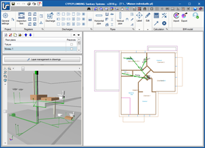
CYPEPLUMBING Sanitary Systems
Representation of vertical spans parting from drainage equipment
In the previous version of CYPEPLUMBING Sanitary Systems, the program did not represent vertical spans parting from drainage equipment in the 3D view nor did it export them to IFC format (although they were taken into account in the analysis and design). As of this version (2018.g), these vertical spans are represented in the 3D view and are exported to the IFC that is generated by the program.
Implementation of water evacuation codes
BS EN 12056, System III (United Kingdom)
The 2018.g version of CYPEPLUMBING Sanitary Systems includes the Eurocode of the United Kingdom BS 6700 (Gravity drainage systems inside buildings) in the list of predefined codes of the program.
CYPEPLUMBING Water Systems
Representation of vertical spans reaching consumption points
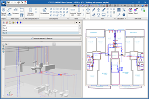
In the previous version of CYPEPLUMBING Water Systems, the program did not represent vertical spans reaching consumption points in the 3D view nor did it export them to IFC format (although they were taken into account in the analysis and design). As of this version (2018.g), these vertical spans are represented in the 3D view and are exported to the IFC that is generated by the program.
Simultaneity calculation methods
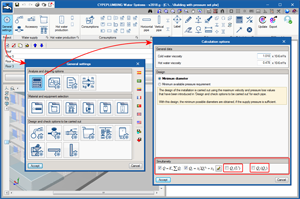
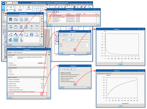
The 2018.g version of CYPEPLUMBING Water Systems includes new simultaneity calculation methods. Additionally, as an aid to users, the graphs of the simultaneity calculation methods can be represented on screen.
Report configuration
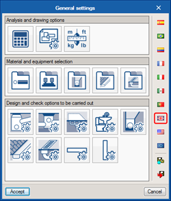
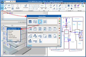
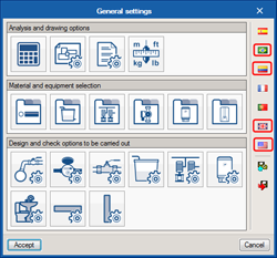
The dialogue box “Report configuration” has been added and can be accessed from the “General settings” panel.
Implementation of water supply codes
BS 6700 (United Kingdom)
The 2018.g version of CYPEPLUMBING Water Systems includes BS 6700 of the United Kingdom (Design, installation, testing and maintenance of services supplying water for domestic use within buildings and their curtilages – Specification) in the collection of predefined codes of the program.
NBR 5626 and NBR 7198 (Brazil)
The 2018.g version of CYPEPLUMBING Water Systems includes the Brazilian NBR 5626 (Instalação predial de agua fria) and NBR 7198 (Projeto e execução de instalaçõe prediais de água quente) codes in the collection of predefined codes of the program.
NTC 1500 (Colombia)
The 2018.g version of CYPEPLUMBING Water Systems includes the Colombian NTC 1500 code (Código Colombiano de Fontanería) in the collection of predefined codes of the program.
IPC and UPC (USA)
The 2018.g version of CYPEPLUMBING Water Systems includes the IPC (International Plumbing Code) and UPC (Uniform Plumbing Code) of the USA in the collection of predefined codes of the program.
CYPELUX
Configuration of the lighting requirements of the installation
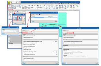
As of the 2018.g version, CYPELUX allows users to establish limit values for the lighting parameters that are calculated by the application. This way, the program can verify the requirements of the main codes. The levels that can be configured by users are:
- General requirements of the project
- Total maximum power (W/m2)
- Specific requirements of each zone
- Normal lighting
- Installation
- Minimum chromatic performance (Ra)
- Maximum total power (W/m2)
- At work plane level
- Minimum maintained average horizontal illuminance (Em) (lux)
- Maximum maintained average horizontal illuminance (Em) (lux)
- Minimum average uniformity (U0)
- Maximum uniform glare rating (UGR)
- Daylight factor
- Maximum VEEI (W/m2)
- Maximum DPI/100lux (W/(m2*100*lux))
- At floor level
- Minimum illuminance (Emin) (lux)
- Minimum average uniformity (U0)
- Emergency lighting
- Installation
- Minimum chromatic performance (Ra)
- Minimum height of the lights (m)
- At floor level
- Minimum maintained average horizontal illuminance (Em) (lux)
- Minimum average uniformity (U0)
- In the equipment
- Minimum maintained horizontal illuminance (lux)
- In evacuation routes
- Central axis
- Minimum horizontal illuminance maintained in the road (lux)
- Uniformity (min/max)
- Centre band
- Minimum horizontal illuminance maintained in the band of the road (lux)
- Central axis
- Installation
- Normal lighting
Since this configuration does not depend on the geometry or specific properties of a project, it may be saved to be used in future projects.
Import standard lighting requirements
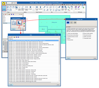
As has been indicated in the previous point, users can establish the lighting requirements the installation is to meet. Now, it is also possible to import the lighting requirements corresponding to certain codes. This way, users can verify that the code requirements are met without having to introduce the corresponding limit values one by one.
EN 12464-1 (EU)
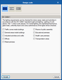
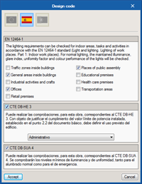
As of the 2018.g version, users can import the lighting requirements of the EN 12464-1 code (Light and lighting – Lighting of workplaces. Part 1: Indoor workplaces) to the general parameters of the application.
To do so, the user license must contain the permit corresponding to this code, which is the same as that which provides access to CYPELUX EN, and the lighting checks of indoor workplaces that are carried out by CYPELUX CTE and CYPELUX RECS.
CTE DB HE 3 and CTE DB SUA 4 (Spain)
The 2018.g version of CYPELUX EN allows users to import the requirements stated in the “Código Técnico de la Edificación” (CTE) of Spain. These are included in the following “Documentos Básicos” and Part 1 of the EN 12464 code:
- CTE DB HE 3 (Spain)
Código Técnico de la Edificación. Documento básico de Ahorro de energía. Sección 3 – Eficiencia Energética de las Instalaciones de Iluminación. - CTE DB SUA 4 (Spain)
Código Técnico de la Edificación. Documento básico de Seguridad de utilización y accesibilidad. Sección 4 – Seguridad frente al riesgo causado por iluminación inadecuada. - EN 12464-1 (EU)
Light and lighting – Lighting of workplaces. Part 1: Indoor workplaces.
To verify the correct lighting of indoor workplaces, the CTE DB HE 3 refers to the EN 12464-1 code.
To be able to import these code limits, the user license must include the modules to use CTE DB HE 3 and CTE DB SUA 4, which are the same that allow for CYPELUX CTE to be used and the Lighting tab of CYPECAD MEP.
RECS (Portugal)
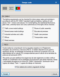
It is also possible to import the lighting requirements of point 9 of the Portuguese code “Regulamento de Desempenho Energético dos Edificios de Comércio e Serviços”. The application will verify the Lighting Power Density limit levels every 100 lux (DPI/100lux) in each zone and bearing in mind the control factors due to occupancy and availability of natural light.
To be able to import these code limits, the user license must contain the same permits that provide access to CYPELUX RECS.
Project report
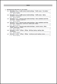
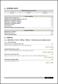
Having defined the verification in the general parameters of the project and obtained the results, the application generates a justification report of the project. This report is divided into two chapters, the first contains the general checks of the project and the second the specific requirements of each zone.
Results consultation
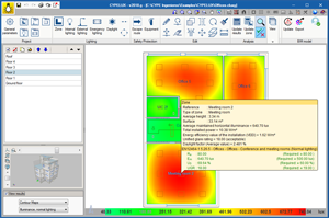
A new option has been added in the toolbar that allows users to, once the project has been analysed, to show a document with the properties and individual checks of a zone.
Export attached documents to the BIM model
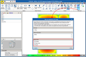
As of the 2018.g version, CYPELUX allows users to attach project reports (in PDF format) and the quantities of the project (in the standard FIEBDC-BC3 format), to the IFC format that is generated by the application. Users can choose which of these documents are to be included in the project using the configuration panel of the export to IFC format.
CYPESOUND, CYPESOUND CTE, CYPESOUND RRAE and CYPESOUND DRAPDE
Import sound sources from the BIM model
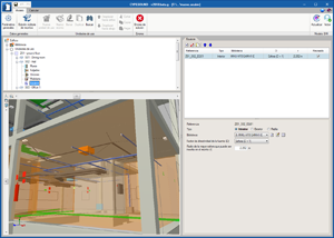
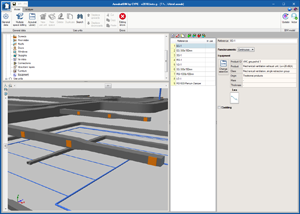
As of the 2018.g version, CYPESOUND (in English), CYPESOUND CTE (in Spanish), CYPESOUND RRAE (in Portuguese) and CYPESOUND DRAPDE (in Italian) are capable of reading and interpreting correctly indoor sound sources that have been defined in the BIM model. This was already being carried out for terminal elements of air conditioning ducts such as grilles and diffusers.
The IFC entities that are recognised by the application, and can be exported to the BIM project by other Open BIM programs of CYPE, include:
- Bathtubs and showers. These objects, together with the remaining sanitary equipment, can be introduced using the free BIM modeller, IFC Builder.
- VRF, Multi-split and Split 1x1 systems. The same way grilles and diffusers can be introduced in CYPETHERM HVAC.
- Terminal air conditioning duct elements (available as of the 2017.e version). This consists of grilles and diffusers. To insert these devices, the BIM program for design of air conditioning installations can be used: CYPETHERM HVAC.
During the import of the BIM model, the application automatically calculates the directivity factor (D) and the radius of the greatest sphere that can be inscribed in the space (r) for each source.
Sound sources can also be imported from the BIM model using this version of AcoubatBIM by CYPE.
AcoubatBIM by CYPE
Intermediate results in reports
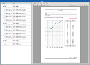
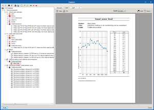
A drop-down list has been added to each results report containing all the intermediate calculations that have been carried out. This way, users can inspect each path sound can take (partitions, openings, flanks, indirect noise...) without having to leave the results window.
Calculation of the sound pressure level generated by building equipment
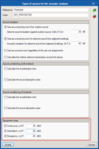
As of the 2018.g version, AcoubatBIM by CYPE allows users to define indoor noise sources, which are generally due to equipment that is installed in the building. A product from the Acoubat database can be associated to each type of source, and in the case of pipes, a cover. Users must provide details of equipment noise (continuous, intermittent or emergency) with the aim to group all the equipment of the same activity and check the acoustic pressure value against the limit established for each space in the general parameters of the project.
Import sound sources from the BIM model
As well as interpreting the geometry of the project, now it is possible to read and interpret indoor sound sources defined in the BIM model, this way, increasing the degree of integration of AcoubatBIM in the Open BIM workflow. The IFC entities that are recognised by the application, and can be exported to the BIM project by other Open BIM programs of CYPE, include:
- Bathtubs and showers
These objects, together with the remaining sanitary equipment, can be introduced using the free BIM modeller, IFC Builder. - Terminal air conditioning duct elements
This consists of grilles and diffusers. To insert these devices, the BIM program for design of air conditioning installations can be used: CYPETHERM HVAC. - VRF, Multi-split and Split 1x1 systems
The same way grilles and diffusers can be introduced in CYPETHERM HVAC.
Sound sources can be imported from the BIM model using this version of CYPESOUND and its corresponding versions to verify the acoustic requirements of national codes (CYPESOUND CTE, CYPESOUND RRAE and CYPESOUND DRAPDE).
New parameters for the advanced search of the database
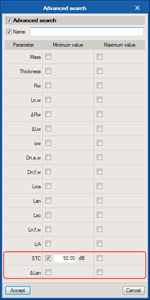
In the previous version (2018.f) acoustic indices were added to the advanced search tool of the database. In the 2018.g version, two more acoustic indices have been added to this search tool:
- STC: Sound transmission class (dB)
- ΔLan: Normalized sound pressure level reduction (dB)
Update of the acoustic requirements defined in the program for the French (NF NRA 2000) and Italian (D.P.C.M. 5 dicembre 1997) codes
Se han modificado los requisitos acústicos que el programa permite importar, correspondientes a las normas de Francia e Italia, con objeto de contemplar las exigencias relativas al ruido de instalaciones.
Portuguese sound code RRAE
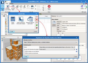
A partir de la versión 2018.g, AcoubatBIM by CYPE permite importar la configuración de los límites acústicos recogidos en los diferentes artículos del "Regulamento dos Requisitos Acústicos dos Edifícios".
En concreto, se han implementado los siguientes tipos de proyecto:
- Artigo 5. Edifícios habitacionais e mistos, e unidades hoteleiras.
- Artigo 6. Edifícios comerciais e de serviços, e partes similares em edifícios industriais.
- Artigo 7. Edifícios escolares e similares, e de investigação.
- Artigo 8. Edifícios hospitalares e similares.
- Artigo 9. Recintos deportivos.
- Artigo 10. Estações de transporte de passageiros.
- Artigo 10-A. Auditórios e salas.
CYPEFIRE Sprinklers
Classification of pipes
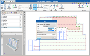
As of the 2018.g version, CYPEFIRE Sprinklers classifies horizontal pipes into branch lines and cross mains. This classification allows for a better analysis of the sprinkler system to be carried out, for example when calculating distances between supports and for the automatic selection of pipes to be held by seismic supports within their zone of influence (which have been implemented in this version).
Therefore, horizontal and vertical pipes (the latter were already divided into different classes as of previous versions) are classed as follows:
- Branch lines
Pipes that supply sprinklers directly or via hanging pipes. - Cross mains
Pipes that supply the branch pipes, directly or via vertical pipes. - Riser
Vertical pipes that supply cross mains via different floors. - Vertical pipe
Vertical pipes that supply cross mains within the same floor. - Hanging pipe
Vertical pipes that supply the sprinklers from the branch lines.
Calculation of the distance between supports and seismic supports
As of the 2018.g version, CYPEFIRE Sprinklers automatically calculates the distances between supports and seismic supports. This calculation is carried out as follows:
- Supports
The distance is calculated via the cross mains or branch lines until the closest support is found. - Lateral support
The distance is calculated via the cross mains or branch lines until the closest lateral support is found. - Longitudinal support
The distance is calculated via the cross mains until the closest longitudinal support is found. - 4-way support
The distance is calculated via the risers until the closest 4-way support is found.
Influence zones of seismic supports
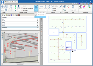
One of the main advantages of the 2018.g version with respect to the previous version is the new tool to create influence zones of seismic supports. As of this version, the list of spans each seismic support must hold will be updated automatically depending on the type of support and the types of pipes that are located within its influence zone.
To introduce an influence zone, its outline must be marked and, if there are different seismic supports within that influence zone, choose the support to which this influence zone belongs.
Layer management
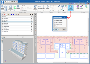
The section “View”, which contains the new tool “Layer management”, has been added to the top menu. This tool aids users to use the program when there are many elements on the floor plans that hinder the design of the sprinkler system. Using the layer management option, users can hide or show layers that contain “Protection areas”, “Area of operation”, “Influence zones” or “Racks”.
CYPEFIRE Design
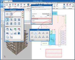
Equipment symbols
As of the 2018.g version, the symbols of the fire safety equipment of CYPEFIRE Design can be edited. Therefore, depending on the code that is used and the type of fire safety equipment, CYPEFIRE Design users can select amongst the symbols that have been implemented in the program for the following equipment:
- Extinguishers
- Fire hose reels
- Hydrant
- Dry standpipe
- Detectors
- Manual buttons
- Fire alarm control panel
- Alarm sirens
Equipment properties
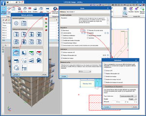
As of the 2018.g version of CYPEFIRE Design, the minimum requirements of the equipment in zones and risk zones can be defined.
Within the “Requirement configuration” menu, another menu “Properties of the equipment” has been added where users can select the classification of the equipment that will be required in the zone as well as its efficiency.
The properties can be defined in the requirements for the following equipment:
- Extinguishers
The type of extinguisher has to be defined (ABC powder, CO2, Pulverised water, etc.), mobility (portable or on wheels) and its minimum efficiency. - Fire hose reels
The minimum diameter of the fire hose reel has to be defined. - Dry standpipe
The minimum diameter of the dry standpipe and the minimum diameter of the outlet valve have to be defined. - Hydrant
The diameters of the central inlet and lateral inlet have to be defined. - Alarm sirens
The type of alarm siren has to be defined.
CYPETHERM Improvements
Integration of CYPETHERM improvements in the Open BIM workflow
With the 2018.g version, CYPETHERM Improvements can be downloaded from the BIMserver.center platform and is included in the Open BIM workflow.
As occurred in previous versions, for CYPTHERM Improvements to carry out the analysis of improvement measures in building, it must import the required information from energy simulation CYPETHERM programs that use the EnergyPlus analysis engine (CYPETHERM HE Plus, CYPETHERM RECS Plus, and CYPETHERM EPlus), CYPETHERM C.E. of Italy, CYPETHERM REH of Portugal and CYPETHERM RT2012 and CYPETHERM RTExistant of France. This information can also be generated directly in CYPETHERM Improvements, but the most efficient way is to import it from the indicated programs.
In previous versions, this information was exported from the aforementioned programs and was imported in CYPETHERM Improvements using XML format files. Now, the version of CYPETHERM Improvements that is downloaded from the BIMserver.center platform obtains this information from the IFC files that are generated by CYPETHERM programs using the Open BIM workflow.
The version of CYPETHERM Improvements that is downloaded from the Download Area of the CYPE website continues to relate itself with CYPETHERM programs by interchanging XML format files.
CYPETHERM EPlus, CYPETHERM HE Plus and CYPETHERM RECS Plus
TOSHIBA 1x1 split equipment
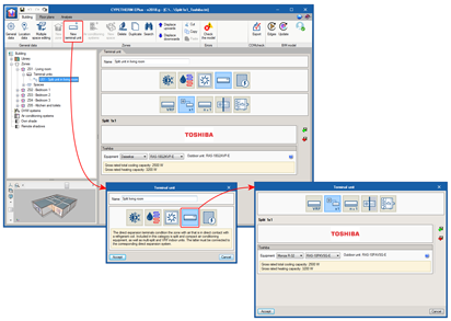
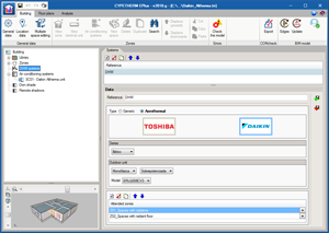
As of the 2018.g version users can simulate TOSHIBA 1x1 split floor and ground equipment. This equipment is defined as terminal units in each zone.
To add a TOSHIBA 1x1 split, a new terminal unit must be added and select the direct expansion category where the 1x1 split button appears. In the panel that opens upon pressing this button, users can choose amongst the various TOSHIBA wall and ground split models.
Several indoor 1x1 split-type units can be defined in the same thermal zone. In the simulation, EnergyPlus will sequentially use the terminal units that are located in the same zone, in the order they have been defined.
DAIKIN Altherma aerothermal systems
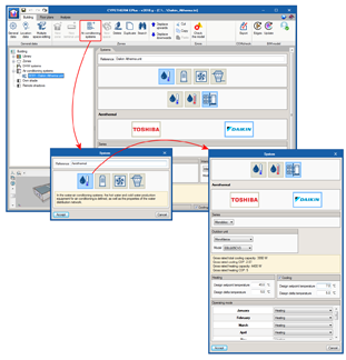
The catalogue of Altherma aerothermal systems from DAIKIN has been incorporated. The DAIKIN logo can be seen in the aerothermal water-air conditioning systems category. In the panel that opens when clicking on the logo, users can choose amongst the three Altherma series equipment: Monobloc, Bibloc and HT.
Depending on the series that has been chosen, in the panel, users can choose amongst the different indoor and outdoor models of DAIKIN Altherma systems choose whether the system will only be used for heating or also for cooling. Additionally, users must specify the working temperature conditions of the installation and its mode of operation during the year.
DAIKIN Altherma equipment has also been incorporated in the domestic hot water systems panel.
Update to version 8.8 of the analysis engine of EnergyPlus™
The 2018.g version of CYPETHERM programs with the EnergyPlus analysis engine uses the new 8.8 version of the engine, published on 30th September 2017.
Definition of the demand of the total domestic hot water of the building
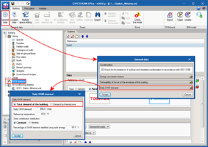
Users can now define a single domestic hot water demand for the whole building. Until now, the domestic hot water demand was defined for each thermal zone. Users can choose between both options in the Building tab > General data > Daily DHW demand.
If the “Total demand of the building” option is chosen, only one system will be defined within “DHW systems”, which will be that seeing to the total demand of domestic hot water.
New interface for the definition of air conditioning systems
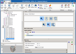
As of the 2018.g version, CYPETHERM programs with the EnergyPlus analysis engine contain a new, more functional and intuitive interface to define air conditioning systems.
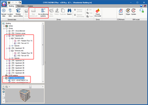
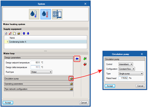
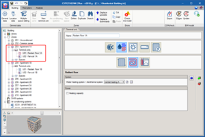
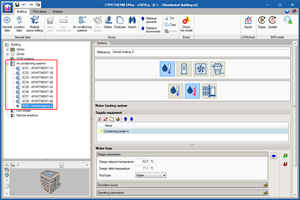
In CYPETHERM EPlus, HE Plus and RECSPlus, the air conditioning installation is divided into Terminal units and Air conditioning systems. Until now, both parts were defined in the same general panel. This panel has been removed and as of the 2018.g version, terminal units are defined within each thermal zone, whilst air conditioning systems are defined in their own section. Now, the terminal units and air conditioning systems created by users are added as elements in the tree diagram located in the top left of the screen, and therefore all the options and editing methods that are used for the elements of the tree are applicable.
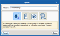
To create an air conditioning system, the new Air conditioning systems button is used. The air conditioning systems available in previous versions have been renamed and classed by type. Hence, in the first window of the assistant, users can choose following the buttons from left to right, amongst:
- Water-air conditioning systems
Located here are water heating and cooling systems and aerothermal systems. - Direct expansion systems
Variable refrigerant flow (VRF) and multi-split outdoor units can be defined here. - Air-air conditioning systems
Users must first choose the type of system (constant or variable air volume, simple or double duct) and then the type of air conditioner. - Water condensation systems
The water circuits for coolers are defined here (these circuits were previously defined together with the cooling by water circuit) as are heat pumps.
In the second window of the assistant, the properties of the chosen system are defined. To help users to introduce the data, the properties that can be edited have been grouped depending on the part of the system to which they refer and the texts have been revised. The panel only displays the basic properties of the system users are to define, whilst the variable that configure the details of the system are displayed by clicking on the “Edit” button located to the right of each section. Additionally, the “Default values” button has been added, which allows users to recover the values that were proposed by the program.
By clicking on “Accept”, the air conditioning system that has been created with the assistant is added to the tree diagram, within the Air conditioning systems section. Upon selecting it, its edit panel opens, where users can edit all the properties defined using the assistant.
The project can be analysed when there are air conditioning systems defined in the tree that are not connected to any terminal unit. This way, users can have systems saved in the project that do not affect the simulation.
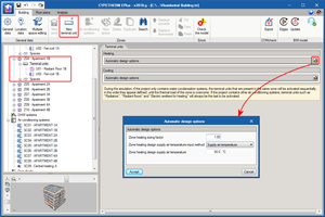
The terminal units are located in each zone. When the “Terminal units” section is clicked on in the tree diagram, the panel in which users can edit the options EnergyPlus™ uses to automatically design the air conditioning equipment that sees to each zone. Users are informed of the priority order with which the different units that are defined in the same zone are simulated.
To add a new terminal unit, the “New terminal unit” is used, which opens an assistant that is similar to that of the Air Conditioning Systems. The terminal units have also been renamed and classed by type, which helps to identify the system to which they can be connected. In the first window of the assistant, following the buttons from left to right, users can choose amongst:
- Constant performance equipment
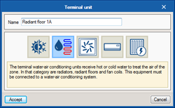
- Terminal unit for air conditioning by water
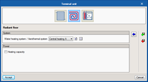
Located here are radiators, radiant floors and fan coils. In this category, that which was previously known as “Radiant heating terminal” has been divided into “Radiator” and “Radiant floor”, with the aim to help users identify this equipment more easily. - Terminal unit for air conditioning by air
Users can choose amongst various air discharge terminals corresponding to different types of air-air conditioning systems. - Direct expansion terminal unit
Autonomous air conditioning equipment is defined here (compact, 1x1 split, water-air heat pump) and indoor direct expansion systems. - Electrical emitter for heating
In the second window of the assistant, the specific equipment is selected and its properties are defined. Most terminal units have to be connected to an air conditioning system. In the “System” section of this window, the systems that are compatible with the chosen terminal unit are indicated. As in previous versions, the terminal unit must be connected to a system to be able to create it. If a compatible air conditioning system already exists in the project, it will be displayed in the drop-down options. If there are no compatible systems, users may create one from the terminal unit panel, or edit an existing one.
By clicking on “Accept”, the terminal unit that has been created with the assistant is added to the tree. When it is selected, its edit panel opens, where users can edit all the properties that were defined using the assistant.
Definition of multiple water air conditioning systems in the same project
As of the 2018.g version of CYPETHERM programs with the EnergyPlus analysis engine, users can define more than one water-cooling and/or heating system in the same project, as long as other types of air conditioning systems are not defined. If other types of air conditioning systems are defined, as occurred in previous versions, only one type of water-air conditioning system can be defined of each of these types (cooling and heating) for all the building.
CYPETHERM HVAC
Improvements in panels and tools
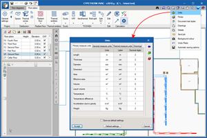
Units panel
Grouping of measurement units in the units configuration panel is organised in the “Primary measurement units”, “General measurement units”, “Thermal measurement units” and “Drawings” tabs. This grouping already existed in previous version but all the units were displayed in the same table, which generated a very long panel.
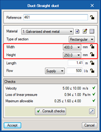
Separate blocking of the width and height of ducts
As of the 2018.g version, users can separately block the height and width of rectangular ducts. Now, one of the two dimensions is fixed so it is not modified during the analysis. In previous versions, when the duct was blocked, both dimensions were blocked at the same time.
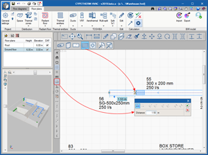
Introduction of elements by lengths
The tool that marks the distance to nearby objects when an element is introduced has been improved. For example, when a grille is moved along duct while it is being placed, a dimensions line appears that indicates the distance to the end of the duct. In previous versions, only the numerical value of the distance appeared.
Return to the 2018 version download area
Tel. USA (+1) 202 569 8902 // UK (+44) 20 3608 1448 // Spain (+34) 965 922 550 - Fax (+34) 965 124 950
