
- Installation of CYPE programs in Russian
- Code implementation and improvements in its application
- Concrete code
- Code regarding loads on structures. Wind loads
- Code regarding loads on structures. Seismic loads
- CYPECAD
- New options and improvements in the advanced beam editor
- Post-tensioned slabs. Instantaneous and differed post-tensioned losses
- Integrated 3D structures
- CYPE 3D
- CYPECAD MEP
- CYPETHERM ASHRAE LOADS
- CYPETHERM ISO 10211
- Arquimedes and job control
Installation of CYPE programs in Russian
As of the 2015.e version, CYPECAD, CYPE 3D and CYPE-Connect can be installed in Russian.
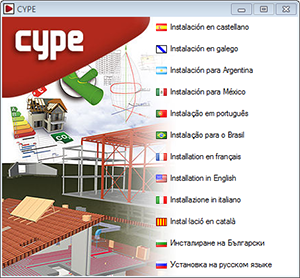
As of the 2015.e version, the files required to install CYPE programs can be downloaded at the following webpages, depending on the language in which they are to be installed:
- Installation in Spanish, Catalan, Galician, Spanish for Argentina, Spanish for Mexico, French, English, Portuguese, and Italian
The file to be downloaded to install the CYPE programs can be done so from the download area of the following CYPE webpages:
- Spanish

- French
- Portuguese
- Italian
- Spanish
- Installation in English, Russian and Bulgarian
The file to be downloaded to install the CYPE programs can be done so from the download area of the following CYPE webpages:
- English
- Bulgarian
- English
It is also possible to install CYPE programs using the Download Manager, which is available in all of CYPE’s Download Area webpages. The Download Manager allows for the programs to be installed in any of the languages available: Spanish, Catalan, Galician, Spanish for Argentina, Spanish for Mexico, French, Portuguese, Italian, English, Russian and Bulgarian. ![]()
Code implementation and improvements in its application
Concrete code
BAEL-91 (R99) (France) and NTCRC: 2004 (Mexico)
- BAEL-91 (R-99) (France)
Fascicule n°62 – Titre I- Section I Règles techniques de conception et de calcul des ouvrages et des constructions en béton armé suivant la méthode des états limites – BAEL 91 révisé 99.
- NTCRC:2004 (Mexico)
Normas técnicas complementarias del reglamento de construcciones para el Distrito Federal
These codes were already implemented in CYPECAD, CYPE 3D and other CYPE programs as of previous versions. Now, in the 2015.e version, these codes are implemented in “Punching shear verification” and hence, also in the punching shear check carried out by CYPECAD in accordance with code criteria. This check was implemented in CYPECAD in the 2015.a version and, since then, coexists with the tangential stress check. ![]()
Code regarding loads on structures. Wind loads
NCh432-2010 (Chile)
Diseño structural. Cargas de viento.
Implemented in CYPECAD.
Code regarding loads on structures. Seismic loads
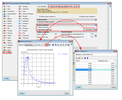
NCh433.Of1996 Mod.2009 (D°n°61. De 2011) (Chile)
Norma Chilena Oficial Diseño Sísmico de Edificions (Includes modifications of decree n° 61 (V. and U.) of 2011).
This code was already implemented in previous CYPECAD and CYPE 3D versions. Now, with the 2015.e version, a user seismic spectrum can be defined. A design spectrum must be defined to carry out the seismic analysis of the structure. Each seismic resistance code provides the criteria that are to be followed within a specific territory for the seismic action to be considered in the project. Nonetheless, the project designer can adopt, under his/her responsibility, different criteria to that established in the code. The program offers different ways to proceed for the use of either way. The design seismic spectrum can be:
- Calculated in accordance with that specified in the seismic code to be applied.
- Specified by users based on his/her criteria.
CYPECAD
New options and improvements in the advanced beam editor
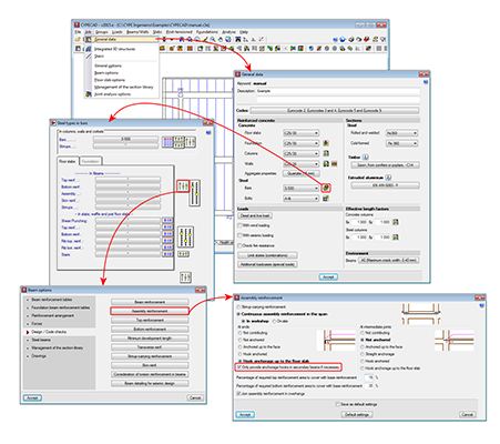
New assembly reinforcement and skin reinforcement design options have been implemented and can be used in jobs for which the concrete and seismic (if applicable) codes allow for the use of the advanced beam editor. ![]()
Assembly reinforcement design options
A new option “Only provide anchorage hooks in secondary beams if necessary” has been implemented. This option is active by default, and so has the same effect as in previous versions. If the option is deactivated, the assembly reinforcement hook will always be provided at secondary beams.
Skin reinforcement design options
A series of design options for skin reinforcement have been implemented. In previous versions, users could only indicate as of which beam depth the skin reinforcement was to be placed, and once placed, the maximum spacing it was to have for floor slabs and beams in floor slabs and foundations had to be defined. Now these options can be edited by selecting the “Minimum reinforcement” button (skin reinforcement dialogue box – see image). Additionally, three new options have been implemented:
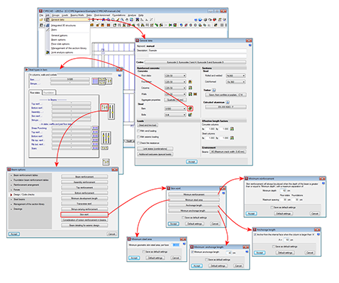
- Minimum steel area
Allows users to specify the minimum skin steel area at each side of the beam. If the steel area indicated by the design code is greater than that indicated in the option, the program will apply the greatest value.
- Anchorage length
Allows users to anchor skin reinforcement as of the internal face of the column where the dimension of the column in that direction is greater than a user specified value . For other cases, the skin reinforcement will be anchored as of the column axis. This option avoids having to provide excessive anchorage lengths in wide columns.
- Minimum anchorage length
Allows users to indicate the minimum anchorage length for the skin reinforcement. The program will check the minimum length indicated by the code and will apply the greater of the two.
Frame drawing improvements
The frame drawings in the advanced beam editor have been improved when the option to draw larger bars further away has been activated.
Post-tensioned slabs. Instantaneous and differed post-tensioned losses
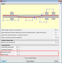
The possibility to separately define the reinforcement loss for instantaneous and differed post-tensioned slabs has been added. Therefore, when analysing, two post-tension loadcases will appear: one with instantaneous losses and another with total losses (instantaneous + differed). A new combination will also appear in the combinations in which the initial post-tension loadcase will act with the self-weight of the structure, so the post-tensioning without any loading, one of the most critical steps when tensioning the tendons of the floor slab, can be controlled.
Integrated 3D structures
The precision of the window in which the elevation difference of the connections is defined, has been increased to 1mm. In previous versions it was limited to 5mm.
CYPE 3D
Copy elements in continuous mode
The option “Copy elements” (Job > Copy Elements) allows users to copy a selection of elements to a new position. As of the 2015.e version, the same elements can be copied repeatedly without having to be reselected.
CYPECAD MEP
Thermal analysis for Spain. CTE DB HE 1
Optimisation of the infiltration flow calculation
The process to calculate the infiltration flows in accordance with the EN 15242 code (detailed iterative method) has been optimised. The time required to calculate the annual simulation in hour intervals has been reduced by half.
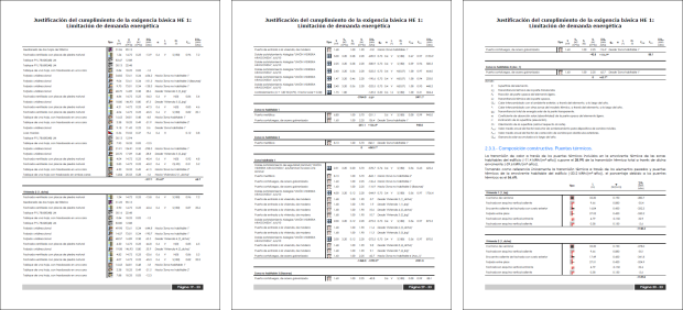
Justification report improvements
The legibility in the CTE DB HE 1 justification report has been improved by adding different icons in the tables referring to the elements of the thermal model (light and heavy elements, and thermal bridges), which refer to the different element types defined in the model.
CYPETHERM ASHRAE LOADS
Tables, graphs and charst for each job element
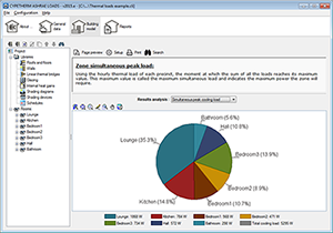
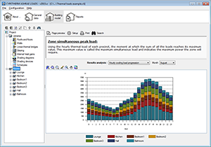
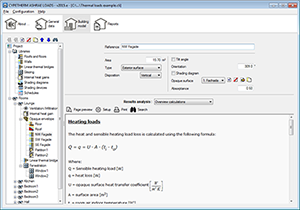
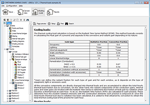
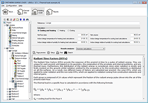
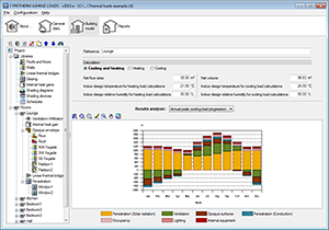
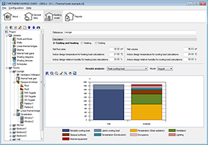
As of the 2015.e version, CYPETHERM ASHRAE LOADS has broadened its immediate result output to offer a better understanding of the calculations that have been carried out and provide the analysis of the effects each component of the job has on the final result of the thermal loads.
To do so, the program provides tables, graphs and charts for each element of the job and are updated when components are added or properties are modified, without having to print out the report of the results, allowing user to carry out a direct and immediate analysis.
The tables, graphs and charst that are visible for each job element are grouped in a drop-down menu called “Results analysis”. This menu also contains the “Overview calculation” option, which, when selected, provides the detailed calculations for each component and the parameters that have been considered. This way, a justification report of the heating and cooling thermal load calculation process is obtained.
CYPETHERM ISO 10211
New types of thermal bridges
As of the 2015.e version, CYPETHERM ISO 10211 analyses two new linear thermal bridges:
- Intersection between the façade and flat roof
- Intersection between the façade and floor slab overhang
New materials libraries
New material libraries have been added. A library with materials of the EN ISO 10456 code and another with the materials of the LIDER library have been added to the existing “Matériaux décrits dans la norme RT 2005”.
 Intersection between the façade and flat roof |
 Intersection between the façade and floor slab overhang |
More information can be found on the webpage. ![]() .
.
Arquimedes and job control
Quantity import from “ArchiCAD® 18 (64-bit)”
The 2015.e version of Arquimedes has been updated to adapt the quantity import from ArchiCAD for “ArchiCAD® 18 (64-bit)”.
Return to the 2015 version download area
Tel. USA (+1) 202 569 8902 // UK (+44) 20 3608 1448 // Spain (+34) 965 922 550 - Fax (+34) 965 124 950