
- Code implementation and improvements in its application
- CYPECAD
- ABNT NBR 6118:2014 concrete code (Brazil)
- Integration of the Punching shear verification program in CYPECAD
- Metal 3D – CYPE 3D
- Change of the name of the program
- Improvements and new data introduction tools
- Section library management
- Assign sections to bars
- Layer management (bars and panels)
- Move, rotate, copy and copy with symmetry
- Import DXF and DWG files
- Move bar end
- Select and edit loadcases (on bars, on nodes and surface loads)
- Move surface loads
- Generic node
- Edit, check and design connections (integration of CYPE Connect)
- Export to 64-bit Tekla® Structures
- CYPE 3D – Example” manual update
- CYPE-Connect
- Code implementation
- Implementation of new connection types in CYPE-Connect
- Baseplates in CYPE-Connect
- Arquimedes and Job control
Code implementation and improvements in its application
Concrete code
ABNT NBR 6118:2014 (Brazil)
Norma Brasileira ABNT NBR 6118 (2014). Projeto de estruturas de concreto – Procedimento.
Implemented in CYPECAD, CYPE 3D (Metal 3D), Punching shear verification, Stairs, Flat slabs, Corbels, Great depth beams, Foundation elements and Continuous beams.
Rolled and welded steel code
ABTN NBR 8800:2008 (Brazil)
ANSI/AISC 360-05 (LFRD) (USA – International)
ANSI/AISC 360-10 (LRFD) (USA – International)
CAN/CSA-S16-01 (Canada)
- ABTN NBR 8800:2008 (Brazil)
Projeto de estruturas de aço e de estruturas mistas de aço e concreto de edificios. - ANSI/AISC 360-05 (LFRD) (USA – International)
Specification for Structural Steel Buildings. - ANSI/AISC 360-10 (LRFD) (USA – International)
Specification for Structural Steel Buildings. - CAN/CSA-S16-01 (Canada)
Limit States Design of Steel Structures.
These codes were already implemented in previous versions of CYPECAD and Metal 3D (CYPE 3D as of the 2015.a version). As of the 2015.a version, these design codes have been implemented for the design and check of steel connections in CYPE-Connect.
CYPECAD
ABNT NBR 6118:2014 concrete code (Brazil)
Norma Brasileira ABNT NBR 6118 (2014). Projeto de estruturas de concreto – Procedimento.
This Brazilian concrete code, which entered into force on the 29th May 2014, has been implemented in CYPECAD and other CYPE software programs of the 2015.a version ![]() .
.
Integration of the Punching shear verification program in CYPECAD
Integration and coexistence with the point tangential stress check
Punching shear verification, was implemented in the 2013.e version. This program was designed to operate as an independent program (within the Structures group of the main CYPE program menu) and as a tool within CYPECAD. Since the 2013.e version, it has only operated as an independent program until now, in the 2015.a version, where it has been implemented to work within CYPECAD ![]() .
.
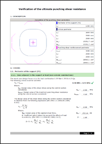
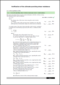
Punching shear verification checks the Failure Limit State of concrete for punching shear in flat and waffle slabs exposed to concentrated loads from rectangular or circular supports (in both the independent program and in CYPECAD). The program can check slabs with or without transverse punching shear reinforcement (reinforcement inclined at 45º or beam-type reinforcement), takes into account the presence of openings or lightweight zones in the slab, and the position of the supports (by indicating whether it is an internal, edge or corner support in the independent program and by the geometry of the floor slab in CYPECAD).
In CYPECAD, the Failure Limit State check for punching shear is also carried out on mat foundations.
By integrating “Punching shear verification” in CYPECAD as of the 2015.a version, the ultimate limit state check for punching shear in accordance with code criteria has been incorporated. Nonetheless, the point tangential stress check carried out up to now in CYPECAD remains, as does the design of the transverse reinforcement in accordance with the same check criteria.
- Point tangential stress check (punching shear for versions before the 2015.a version)
A tangential stress verification is carried out on surfaces which are concentric to the perimeter of the support, between a distance of half the depth of the slab from the support and at intervals of 0.75 times the depth of the slab. The value of the tangential stress at the intersection points of the mesh with the punching shear perimeter is obtained using the shears at the nearby nodes by means of linear interpolation. This stress is compared to the maximum punching shear tangential stress resistance, which is calculated using the corresponding concrete code. This approach, based on point tangential stress checks at the mentioned perimeters, is different to the punching shear failure check provided by different concrete codes.
- Punching shear in accordance with code criteria (implemented in CYPECAD as of the 2015. Version)
In general, design codes use a nominal tangential stress within a critical surface area which is concentric to the loaded zone, and is calculated taking into account the reaction of the support and the moments it transfers to the slab.
The punching shear analysis method in accordance with code criteria is a simplification proposed by different codes; which also allow for the use of, as alternative method, procedures which provide a more precise evaluation of the tangential stress at surface areas which are concentric to the perimeter of the support, which is the case of the tangential stress check method carried out in CYPECAD as of earlier versions.
Therefore, the final result obtained by both procedures may not coincide, even though both are valid.
The reinforcement calculated by CYPECAD, depending on the point tangential stress, can be used as a reference to introduce punching shear reinforcement (reinforcement at 45º angles or beam-type reinforcement). Once introduced, CYPCAD automatically checks the reinforcement that has been provided by carrying out a punching shear verification in accordance with code criteria. If punching shear reinforcement is provided, the tangential stress reinforcement located within the surface area concentric to the support and limited by the critical punching shear perimeter, must be deleted to avoid it being duplicated in drawings and job quantities. To do so, a tool has been included in CYPECAD (as well as other new options in the punching shear dialogue box) which allows for users to eliminate the tangential stress reinforcement ![]() .
.
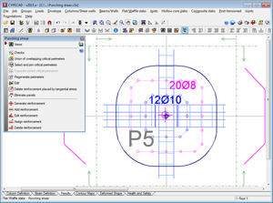
Operation of the punching shear check in CYPECAD
During the analysis of the job, CYPECAD checks the point tangential stress on flat and waffle slabs and mat foundations. If necessary, CYPECAD designs the transverse reinforcement (vertical bars) in accordance with the same criteria. If users wish so, they can carry out the punching shear check and, if required, provide transverse punching shear reinforcement (bars inclined at 45º or beam-type reinforcement) which will substitute those that have been obtained using the tangential stress check and lie within the critical punching shear perimeter of the support that has been checked.
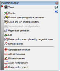
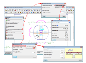
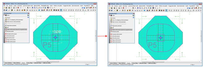
A series of options have been implemented in the “Punching shear” dialogue box (Results > Flat/Waffle slabs > Punching shear) to carry out the punching shear check and provide the required reinforcement:
- Views
Using this option, users can select the flat and waffle slab reinforcement to be seen on screen. - Checks
Allows users to view on screen, print or export (Text, HTML, PDF, RTF, DOCX) all the Failure Limit State checks for punching shear carried out by the program at the selected support. - Union of overlapping critical perimeters
This option creates the union of the intersecting critical perimeters of the supports. - Select and join critical perimeters
This option joins two or more critical perimeters. - Separate joined critical perimeters
This option separates critical perimeters which had previously been joined. - Regenerate perimeters
The program obtains the perimeters each time the job is analysed and when there significant data changes which may affect its composition. This is not carried out for other types of changes, such as when the width of a beam has been modified. Users can use this option, if deemed necessary, after having carried out this type of changes. - Edit
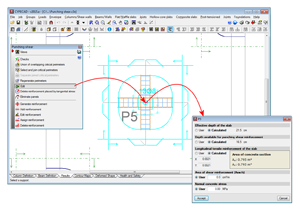
Having selected a support, this option opens a dialogue in which all the data that has been obtained automatically by CYPECAD is displayed, so it can be modified by users (effective depth of the slab, depth available for punching shear reinforcement, slab tensile reinforcement area).
An additional area “Asw” (cm2/m) of punching shear reinforcement and a normal concrete stress (kp/cm2) can also be added. For example, the section of transverse reinforcement of a beam (cm2/m) which lies within the zone contained by the critical punching shear perimeter is not taken into account automatically by the program (with regards to punching shear reinforcement) but, by consulting it using CYPECAD’s advanced beam editor (Results > Beams/Walls > Edit beams), it can be included in the “area of punching shear reinforcement (Asw/s)” field of the edit dialogue of the support selected using this option.
All the data defined here is used to generate the critical perimeter and carry out the punching shear resistance checks. - Delete reinforcement placed by tangential stress
T he reinforcement calculated by the program due to point tangential stress can be used as a reference to introduce punching shear reinforcement (bars inclined at 45º angles or beam-type reinforcement) and then carry out a punching shear verification in accordance with code criteria. In this case, the tangential stress reinforcement located within the critical punching shear perimeter should be deleted. This reinforcement can be deleted using this option and so avoid duplicating it on drawings and job quantities.
- Eliminate panels
This option allows users to select panels for which punching shear checks are not to be carried out. - Generate reinforcement
This option allows users to introduce two orthogonal reinforcement configurations at a support. - Add reinforcement
Users can add reinforcement in any direction and at any support. - Edit reinforcement
Allows users to edit punching shear reinforcement introduced at a support. - Assign reinforcement
Using this option, users can introduce reinforcement bars equal to other reinforcement that is already present. - Delete reinforcement
Deletes the selected reinforcement.
Punching shear reinforcement quantities and drawings
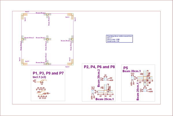
A new drawing, “Punching shear reinforcement bars” has been implemented (File > Print > Job drawings > add a drawing > select “Punching shear reinforcement bars” drawing). A plan view of the floor displaying the punching shear reinforcement provided by users, the detailing, take-off table and quantities summary are all displayed in this drawing.
The punching shear reinforcement quantities are also contained in the takeoff report (File > Print > Job report > Job takeoffs).
Codes implemented for the punching shear check
The concrete codes for which the punching shear check is available in CYPECAD for the 2015.a version are:
- ABNT NBR 6118:2014 (Brazil)
Norma Brasileira ABNT NBR 6118 (2014). Projeto de estruturas de concreto - Procedimento. - ABNT NBR 6118:2007 (Brazil)
Norma Brasileira ABNT NBR 6118 (2007). Projeto de estruturas de concreto - Procedimento. - Eurocode 2
The adapted codes for each country include their corresponding national application document.
- Eurocode 2 (EU)
EN 1992-1-1:2004/AC 2008. Design of concrete structures. Part 1-1: General rules and rules for buildings. - Eurocode 2 (France)
NF EN 1992-1-1 :2005/NA: Mars 2007. Calcul des structures en béton. Partie 1-1 : Règles générales et règles pour les bâtiments. - Eurocode 2 (Portugal)
NP EN 1992-1-1:2010/NA. Projecto de estructuras de betão. Parte 1-1: Regras gerais e regras para edifícios.
- Eurocode 2 (EU)
- EHE-08 (Spain)
Instrucción de Hormigón Estructural. - NTC: 14-01-2008 (Italy)
Norme tecniche per le costruzioni.
Required license permits
For CYPECAD to be able to perform the punching shear check in accordance with code criteria, the user license must have the required permits to use the “Punching shear verification” program. Additionally, the user license must include, at least, the permits required to design the type of floor slab where the punching shear check is to be carried out (flat slabs, waffle slabs or mat foundations).
Metal 3D – CYPE 3D
Change of the name of the program
As of the 2015.a version, Metal 3D (whose name depended on the language in which it was installed) is now called CYPE 3D regardless of the language in which it is installed.
Improvements and new data introduction tools
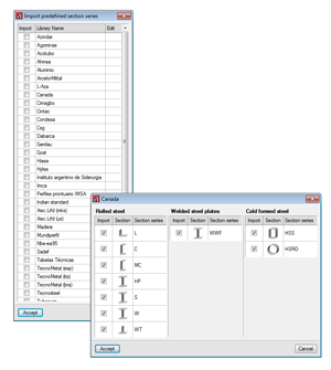
Section library management
The “Management of the section library” option (Job menu) allows users to import predefined section series into the current job, establish the default lists available for new jobs and export section series of the current job to different file formats. All this is possible using three options that appear in a dialogue box when the “Management of the section library” option is executed.
Assign sections to bars
As well as the new section library management, the process undertaken to assign sections to the bars to be introduced and those already introduced has been improved:
- New (Bar menu)
As of the 2015.a version, the “New” option in the “Bar” menu opens a dialogue box where users can:
- Select the section of the bar that is going to be introduced. This can be done in two ways:
- By selecting it from the libraries available in the job (the same way as with the “Describe section” option).
- By selecting it from a list where the sections used in the job are displayed.
- Establish the layout of the section (adjustment point and rotation angle)
Upon accepting this dialogue box, users can introduce the bar with the section and layout that has been defined, without having to use the “Describe section” and “Describe disposition” options in the Bar menu. - Select the section of the bar that is going to be introduced. This can be done in two ways:
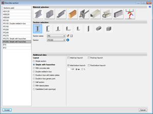
- Describe section (Bar menu)
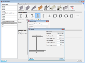
A list of the sections that are being used in the job has been added to the dialogue box that opens upon selecting this option and then selecting a bar, from which users can select a section. Additionally, other options which already existed since previous versions (material selection, type of section, section series, section layout – simple, with haunches, double welded in a box...-, edit section series, access to library management) are located in the same dialogue box (without having to open other dialogues like in previous versions). - Root radius and angle of the flanges of rolled sections
By editing rolled sections, users can define:
- For any rolled section:
- The root radius between the web and flange
- The root radius between the sides of the flanges
- For I-sections and simple channels
- Inclination of the flanges
- For any rolled section:
- New welded section type
I-sections with different flange lengths and variable depth have been added.
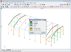
Layer management (bars and panels)
Three options have been created in the “Job” menu, which allow users to class bars and load panels in layers defined by themselves, so they may be viewed in their respective layers and for bars to only interact with the elements of the visible layers.
- Layer management
Allows users to define layers or group views for elements or panels. Users will only be able to interact with elements belonging to layers which are visible. Elements and panels alike will be assigned to the active layer when created. - Assign elements to layers
Users can change the layer of the selected elements. - Assign panels to layers
This allows users to change the layer assigned to the selected load panels.
Move, rotate, copy and copy with symmetry
The 2015.a version includes a wide range of options to define the geometry of the structure. These are located in the “Job” menu and are:
- Move elements
Moves a selection of elements to a new position.
Select the elements to be moved using the left mouse button. Once selected, press the right mouse button, then the left and mark the two points which define the displacement origin and its magnitude. - Rotate elements in the XY plane
Rotates a selection of elements about the global z axis. If the operation is carried out in a 2D view, the rotation will be performed in the plane of the view.
Select the elements to rotate using the left mouse button. Once selected, press the right mouse button, then the left, and mark the two points which define the rotation angle. - Rotate elements about an axis defined by two points
Rotates a selection of elements about an axis defined by two points. If the operation is carried out in a 2D view, the rotation will be performed in the plane of the view. Select the elements to rotate using the left mouse button. Once selected, press the right mouse button, then the left. Mark the two points which define the rotation axis followed by the rotation angle about the axis. - Rotate elements in the XY plane given three points
Rotates a selection of elements about the global z axis with respect to the origin indicated by users and with the angle defined by any three points. If the operation is carried out in a 2D view, the rotation will be performed in the plane of the view. Select the elements to rotate using the left mouse button. Once selected, press the right mouse button, then the left. Mark the point of origin of the rotation and the three points which define its magnitude. - Copy elements
Copies a selection of elements at a new position.
Select the elements to be copied using the left mouse button. Once selected, press the right mouse button, then the left and mark the two points which define the displacement origin and its magnitude. - Element symmetry in the XY plane
Carries out a symmetrical copy of a selection of elements with respect to the plane defined by a vector introduced by users and the global z axis. If the operation is carried out in a 2D view, the symmetry will be carried out with respect to the line defined by the vector.
Select the elements to be copied using the left mouse button. Once selected, press the right mouse button, then the left and mark the two points which define the origin of symmetry and the direction of the vector in the global XY plane. - Element symmetry with respect to a plane
Carries out a symmetrical copy of a selection of elements with respect to a plane defined by three points. If the operation is carried out in a 2D view, the symmetry will be carried out with respect to the line defined by the first two points. Select the elements to be copied using the left mouse button. Once selected, press the right mouse button, then the left and mark the three points defining the plane of symmetry.
Import text files
Generates the geometry of the job automatically using a text file with a specific format. The format these text files are to have is specified in the dialogue box that appears when this option is selected from the “Job” menu to select the file to be imported.
Import DXF and DWG files
The option to import files in DXF and DWG format to automatically generate the geometry of the structure (Job > Import DXF and DWG files) incorporates the following improvements:
- Layer generation
As of previous versions, when CYPE 3D imports a DXF or DWG file, users select the layers of the DXF or DWG which contain the elements to be imported. As of the 2015.a version, the layers selected in the DXF or DWG file are created in CYPE 3D with the same name and colour as they had in the file. Imported bars remain assigned to the same layer as they were in the DXF or DWG file. This is possible because the creation of view layers has been implemented in CYPE 3D.
- Insertion point selection
CYPE 3D requests users to define an insertion point to insert the geometry of the structure obtained from a DXF or DWG file. The program allows users to:
- Import at the position defined in the DXF or DWG file
- Select the reference point for the import
Move bar end
The option “Move end” has been implemented in the “Bar” menu, and allows users to move the end o the selected bar without having to move any other bars connected to the node reaching that end. To move all the bars connected to a node, the “Move” option in the “Node” menu can be used (option available since the first version of Metal 3D).
Select and edit loadcases (on bars, on nodes and surface loads)
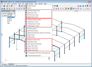
To help users when editing loads, a dialogue box appears on screen (visible loadcase) when any of the load editing options are selected from the “Load” menu (see image).
The visible loadcase at any moment can be selected in this dialogue box.
Three new options have been implemented to modify the loadcase assigned to each load: “Edit loadcases on bars”, “Edit loadcases on nodes” and “Edit surface load loadcases”. These allow for the loadcases of several loads to be edited at the same time.
Move surface loads
The option “Move surface loads” allows users to move the selected load and, as of the 2015.a version, also move surface loads applied at the same zone belonging to other loadcases.
To do so, when this option is selected, a dialogue box appears allowing users to activate or deactivate this possibility. Once the dialogue box has been accepted, the selection can be modified by pressing the right mouse button.
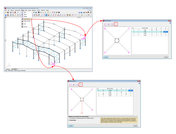
Generic node
The 2015.a version includes a new type of node. “Generic node”. With this type of node, users can define different rotation groups for the same node. Any node of a structure may be defined as a generic node by selecting the ![]() button in the “Internal fixity” dialogue box (Node > Internal fixity).
button in the “Internal fixity” dialogue box (Node > Internal fixity).
Information on how to define the internal fixities of the bars reaching the node can be found by selecting the help button ![]() in the top left-hand corner of the each dialogue.
in the top left-hand corner of the each dialogue.
If the selected node of the structure has a fixity with a coerced rotation, users can define, in the “Internal fixity” dialogue box, how the external coercion is applied to the rotation groups. In this case two options will appear in the bottom part of the dialogue with information on its operation.
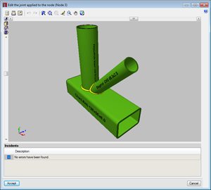
Edit, check and design connections (integration of CYPE-Connect)
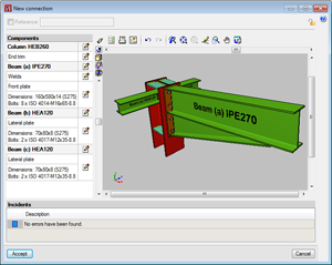
The 2015.a version of CYPE 3D (Metal 3D) allows users to edit, check and design connections for its five joints modules (Joints I, Joints II, Joints III, Joints IV and Joints V). Additionally, baseplates can also be edited, checked and designed.
As of the 2015.a version, CYPE 3D allows users to:
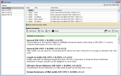
- Check, design and generate the details of bolted or welded joints with rolled and welded I-sections (including the baseplates for these sections) if the user license contains the “Joints I, II, III and IV” modules.
- Check, design and generate the details of welded connections with hollow structural sections (circular hollow sections, rectangular hollow sections, square hollow sections and those created from two channels welded in a box) if the user license contains the “Joints V” module.
- Check, design and generate welded baseplates for any steel column arrangement (simple and composite steel sections; rolled, welded and cold-formed steel sections) if the user license contains the “Baseplates” module.
- Obtain the detailed check reports for each type of joint (including baseplates).
These new features imply the integration of CYPE-Connect in CYPE 3D (Metal 3D). CYPE-Connect was implemented in the 2014.f version and was designed to check, design and generate the details of welded and bolted steel connections with rolled I-sections. CYPE-Connect follows the same design procedure as CYPE 3D, but until now, CYPE 3D could not modify and automatically check the connections designed by the program.
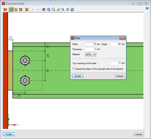
CYPE-Connect also includes new features which allow for it to design and check joint types and baseplates which could only be designed until now with Metal 3D (now CYPE 3D) ![]() .
.
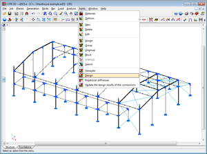
The Joints menu of CYPE 3D has been restructured so steel connections may be edited and checked. All these options affect the edit process, check and design of the joints and baseplates. The new options contained in the “Joints” menu of CYPE 3D are described below:
- Materials
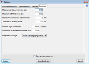
- Options
Allows users to configure the options the program will use to design the connections. - New
Creates a joint, for which users can create multiple connections at the same node. To create a joint, one of the following procedures must be followed:
- To create a joint with all the bars at the node, select the node and press the right mouse button.
- To create a connection at the end of a bar (a baseplate, for example), select the end of the bar and press the right mouse button, or select the node if it is the only element to be used and press the right mouse button.
- To create a joint for a group of bars, select the bars by pressing with the left mouse button in an area close to the node at which the joint is to be creates, then press the right mouse button.
- Delete
- Edit
Edits and checks a joint. When this option is activated, joints are displayed in different colours, depending on whether they fail any checks. - Assign
Copies a joint to another of the same type which is defined for a geometrically compatible group of elements (same number and type of elements, same relative positions between them and same fixity at the connection node). - Group
Allows users to group a joint with one of the same type which is defined for a geometrically compatible group of elements (same number and type of elements, same relative positions and rotations between them and same fixity at the connection node). - Ungroup
- Block
Blocks a joint so it cannot be modified during the design process. - Unblock
- Search
- Generate
Using this option, the program analyses all the nodes of the job and assigns, to those elements without any previously defined connections, the detected joints. - Design
Using this option, the program designs all the joints that have been defined. - Rotational stiffness
Users can consult and modify the values of the rotational stiffness of the joints applied by the program and for those whose rotational behaviour is to be analysed. - Update the design results of the connections
This option updates the design results of the rotational stiffness of the connections of the job once the joints have been edited.
Export to 64-bit Tekla® Structures
As of the 2015.a version, CYPE 3D allows users to export the designed structure to 64-bit Tekla® Structures.
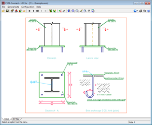
“CYPE 3D – Example” manual update
The “CYPE 3D – Example” manual has been updated so to include the new features of CYPE 3D (section library management, assign sections to bars, bar and panel layer management and the modification of joints and baseplates).
The manual, in English, will shortly be available. The version in Spanish can be downloaded by clicking on the following icon ![]() .
.
CYPE-Connect
Code implementation
The following codes have been implemented to design and check steel joints in CYPE-Connect:
- ABTN NBR 8800:2008 (Brazil)
Projeto de estruturas de aço e de estruturas mistas de aço e concreto de edificios. - ANSI/AISC 360-05 (LFRD) (USA – International)
Specification for Structural Steel Buildings. - ANSI/AISC 360-10 (LRFD) (USA – International)
Specification for Structural Steel Buildings. - CAN/CSA-S16-01 (Canada)
Limit States Design of Steel Structures.
These codes were already implemented in previous versions of CYPECAD and Metal 3D (CYPE 3D as of the 2015.a version).
Implementation of new connection types in CYPE-Connect
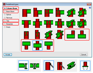
A few types of connections have been implemented, which in previous versions could only be designed by the Joints I, II, III, IV and V modules in Metal 3D (now CYPE 3D):
- Column-Beam connections (continuous beam with column above or below)
- Beam-Beam connections (beam connected to the web of the other beam)
- Splice connections (of hollow structural sections)
- Ties (column with a tie at the flange or web and beam with a tie at the web)
- Baseplates (detailed in the following section )
Therefore, as of the 2015.a version, the types of joints that can be designed, checked and edited by CYPE-Connect are the same as those for CYPE 3D (Metal 3D) ![]() .
.
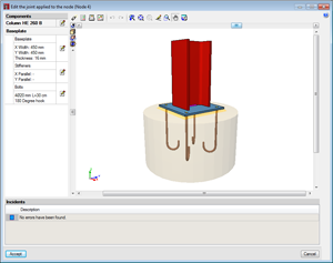
Baseplates in CYPE-Connect
The design and check of baseplates have been implemented in CYPE-Connect. With this implementation, the joints and baseplates that can be designed, checked and edited by CYPE-Connect are the same as those for CYPE 3D (Metal 3D).
As is the case with CYPE 3D (Metal 3D), if the user license contains the Joints I, II, III and IV modules, users can check, design and generate baseplates for rolled and welded steel I-sections. If the users license contains the “Baseplates” module, users can check, design and generate welded baseplates for any steel column arrangement (simple and composite sections; rolled, welded and cold-formed sections).![]()
Arquimedes and Job control
Financial control of the job by applying the Earned Value Management – EVM model
The Earned Value Management (EVM) method is a cost control standard which allows users to follow the expenses and deadlines of a project and provides the information required to make decisions. The model can be applied to a job item, a chapter or the complete job, from the point of view of the Project Management team or the Site Manager.
The EMV model has been taken from chapter 7, Project Cost Management, of the Project Management Book of Knowledge guide (PMBOK) for the American code: ANSI / PMI 99-001-2004.
This model has been implemented in the 2015.a version of Arquimedes so the economic control can be performed by the Site Manager. In future versions, this model will be implemented so it can be applied from the point of view of the Project Management team.
To view the economic control by applying the “EMV” model from the point of view of the Site Manager with Arquimedes, a Gantt chart must be created at job item level to plan the job in phases (months). All these tasks must be linked to cost centres (job items) with updated quantity and study amounts in accordance with the job items in the decomposition tree.
The corresponding charges must be applied to the cost centres and the executed quantities of each job item must be introduced to obtain their execution prices in the corresponding phase designed in accordance with the plan of the project. Additionally, certifications must be closed at the dates corresponding to each planned phase to register both certified quantities and executed amounts. This way, all the information required to obtain the variables of the Earned Value Management EMV) model is obtained.
New charge summary tables
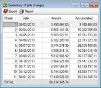
The amount executed of each job item in each phase (month) is obtained using the direct and repercussion charges classified in phases (months). In the 2015.a version of Arquimedes and Job Control, two new options have been added to the View option in the Job Control menu:
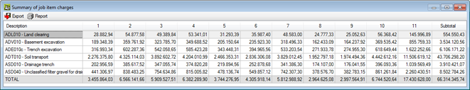
- Summary of job charges
This displays a table that includes the charged partial and accumulated amounts of the job in execution phases (months) in accordance with the closed certifications. - Summary of job item charges
This displays a table that includes the charged partial amounts of each job item of the job in execution phases (months) in accordance with the closed certifications.
Improvement in the presentation of the calculation justification of type A charge repercussions
To improve the calculation presentation of the type A charge repercussions, the Details of the repercussion job items window has been improved. This window appears when a type A repercussion exists on a job item and the repercussion amount is double clicked on.
The repercussion expenses due to theoretical consumption (type A repercussions) are obtained in the following way: charges containing supplies whose amounts are to be shared proportionally amongst job items which contain the same type of supplies in their decomposition (direct expenses) should be assigned in chapters. The distribution is proportional to the theoretical quantity of the supply in the job item. The theoretical quantity is calculated as the product of its yield in the decomposition by the quantity executed in the job item.
If the affected job items have direct charges of the same type of supply, the distribution favours those which no not have these direct charges.
An example of this type of charge could be the case of a supply of concrete to be used on site, yet its exact quantity is unknown, and so the root chapter or the various chapters are directly charged, and so the program will share its quantity evenly amongst the job items containing this supply in their decomposition.
Access to earlier version databases
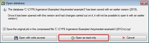
When Arquimedes opens a database saved with an earlier program version, a dialogue box is displayed where users can choose to open the job in read only mode and create a compressed copy.
As of the 2015.a version, Arquimedes allows for these databases to be opened in read only mode, even if they require an update, and so will not appear modified when opened.
Return to the 2015 version download area
Tel. USA (+1) 202 569 8902 // UK (+44) 20 3608 1448 // Spain (+34) 965 922 550 - Fax (+34) 965 124 950