
![]()
- Code implementation and improvements in its application
- CYPECAD
- Interaction of the structure with the construction elements
- Post-tensioned slabs. Point deviation loads of straight sloped tendon spans and representation of the horizontal component of the anchorage
- Calculation of the base shear when floors below ground level are not considered in the dynamic analysis
- CYPE-Connect
- CYPECAD MEP
- Return to the 2014 version download area
Code implementation and improvements in its application
Code regarding loads on structures. Seismic loads
COVENIN 17561:2001 (Venezuela); NEC 11 (Ecuador); Norma Técnica E.030 (Peru)
- COVENIN 1756-1:2001 (Venezuela)
Norma Venezolana COVENIN 1756-1:2001. Edificaciones sismorresistentes. - NEC 11 (Ecuador)
Norma Ecuatoriana de la Construcción. Capítulo 2.-Peligro sísmico y requisitos de diseño. - Norma Técnica E.030 (Peru)
Norma Técnica E.030. Diseño Sismorresistente
These codes were already implemented in CYPECAD and Metal 3D as of previous versions. Now with the 2014.g version, CYPECAD offers two options for users to indicate the value of the Fundamental period of the structure (used to calculate the base shear):
- Based on the code
Only option in previous program versions for these codes. - Specified by the user
Implemented in the 2014.g version for these codes, although this option was already available, as of previous versions, for other seismic codes: CFE 2008 (Mexico), NTC 2004 (Mexico), NC 46:1999 (Cuba) and NSR-10 (Colombia).
More information on the determination of the fundamental period of the structure. ![]()
CYPECAD
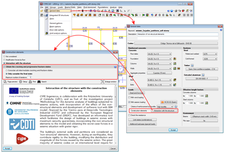
Interaction of the structure with the construction elements
Automatic generation of intermediate states
Using the Interaction of the structure with the construction elements module, users can carry out a dynamic analysis of buildings subjected to seismic action, which includes the effect the non-structural elements used in the partitions and façade have on the building. Furthermore several behaviour models of the building are considered corresponding to different situations or states of these elements.
This module was implemented in the 2014.a version and considered two extreme states: State 1, corresponding to the behaviour of the structure without the effect of any construction elements, and State 2 considering the effect of all the laterally confined construction elements by including their stiffness in the dynamic model and assuming they are completely effective, i.e., that they have not cracked or fractured.
As of the 2014.g version, the program allows for intermediate states to be defined between States 1 and 2. These are generated automatically depending on a fracture criterion which relates the damage suffered by an element with the relative displacement of its ends. These are intermediate states, in which each laterally confined element provides a percentage of its stiffness depending on the level of damage it has reached.
These intermediate states are generated automatically based on the model in which all the construction elements are considered to be effective (State 2). A modal spectral analysis of the model produces a relative displacement between the ends of each construction element which, upon applying the fracture criterion, is interpreted as being a specific level of damage. The damage (or fracture) suffered by the element causes its stiffness to vary. The new stiffness obtained for each construction element is included in the new dynamic model which is used for the next modal analysis. New relative displacements are obtained and each element reaches a new damage level, with their change in stiffness, and so the next model is generated. This process is repeated successively for each seismic loadcase that is considered.
This iterative process stops when the damage level stabilises between two states (which occurs when the difference between the level of damage of the last analysed state and the previous state is less than 5% for each element) or when the maximum number of iterations established by users is reached. This will be the Final state.
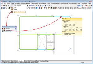
The automatic generation of these intermediate states can substantially multiply the number of seismic loadcases that are considered, hence CYPECAD allows users to configure this iterative process in the Construction elements dialogue box (Job > General data > Loads section > Construction elements option). Users have to activate the Interaction with the structure option (located at the top). Once activated, another option appears: Obtain the cracking and progressive fracture states. If this option is deactivated, CYPECAD will only generate states 1 and 2, as was done in the 2014.a version. If the option: Obtain the cracking and progressive fracture states is activated, the following options appear:
- Consider all intermediate cracking and fracture states
By choosing this option, CYPECAD considers all the states (State 1, State 2 and Intermediate states) that have been generated when designing the structure. By activating this option, the time required to analyse the job could substantially increase, depending on when the Final state is reached. - Only consider the final state
All the states are analysed but CYPECAD only considers State 1, State 2 and the Final state when designing the structure.
Below these options, users can limit the Maximum number of iterations. This number will determine which is the final state, if this state is not reached before the maximum number of iterations has been undertaken
As the structure is analysed several times, if all the cracked intermediate states are considered as of the first analysis, the design process of the structure could be quite long. Therefore, for the first analyses, it is best if Only consider the final state is activated. Once any problems involving the dimensions of the structural elements have been solved (and the follow-up analysis has concluded), users should then consider activating Consider all intermediate cracking and fractured states and maybe increasing the Maximum number of iterations.
To help users decide, as of the 2014.g version, a new option has been implemented: Damage level (Results tab >Loads > Construction elements). Using this option, users can consult the relative displacement and associated damage, per generated state and seismic loadcase of each construction element. This information allows users to know if the iterative process that has been configured is adequate or must be changed:
- If, for any seismic loadcase, the difference between the last state of a construction element and its previous state is greater than 5%, the maximum number of iterations should be increased. Otherwise the number is adequate.
- If the option “Only consider the final state” has been activated and the difference in damage between the final state and the other intermediate states (X1, X2… or Y1, Y2…) is small, users do not have to activate the “Consider all intermediate cracking and fracture states” option.
This check should be carried out for all the construction elements of each floor.
Help explanations are included within the mentioned dialogue box, which describe the implications of these options.
The approximation carried out by the 2014.a version (which can also be carried out as of the 2014.g version, by not activating the Obtain the cracking and progressive fracture states option) is acceptable for buildings with an open-floor ground floor which, generally are irregularly stiff, causing them to be weaker at that floor (buildings whose ground floor is destined to be used as retail precincts, garages…).
Nonetheless, and as it is not possible to generalise for all these cases, it is recommended the 2014.g version be used and that an analysis be carried out taking into account the intermediate cracking or fracture states. Please bear in mind that users who have any 2014 version can update to the latest version for free. Therefore, we recommend these users, especially those whose licence contains the “Interaction of the structure with the construction elements” module, to update to the latest 2014 version. This way, the automatic generation of intermediate states option will be available to them. ![]()
Please recall that the building partitions and façades are considered as being “non-structural” elements, however during an earthquake, they do provide stiffness to the structure, hence modifying the distribution and magnitude of the forces caused by the seismic action. If these structural elements have not been designed accordingly for this distribution, the forces can cause a fragile fracture, endangering the stability of the building, even leading to its collapse. The Interaction of the structure with the construction elements module allows users to consider the effect the non-structural elements have on the structure during an earthquake and as of the 2014.g version, the program automatically generates the intermediate cracked and fractured states. More information on this new CYPECAD tool, unique in today’s market, can be found in the “Interaction of the structure with the construction elements” webpage. ![]()
Post-tensioned slabs. Point deviation loads of straight sloped tendon spans and representation of the horizontal component of the anchorage
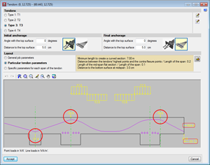
Using the Post-tensioned concrete slabs for buildings module, CYPECAD can design the passive reinforcement of post-tensioned slabs, having calculated the forces in the post-tensioned tendons (bonded or unbonded tendons), based on the properties which have been introduced by users. ![]()
Since this module was implemented, the program generates the line pressure loads acting towards the inside of the curve of the tendons.
Now, with the 2014.g version, the deviation point loads which cause the straight sloped tendon spans are also generated. These loads are represented in the tendon editing box and also on plan with the other tendon deviation loads. Additionally, within the tendon editing box, the horizontal component of the force which causes it to anchor in the slab, is drawn on the axis of the longitudinal section of the slab, as well as the moment that is represented by the eccentricity this component could have when the anchorage is not situated in the axis of the beam.
Calculation of the base shear when floors below ground level are not considered in the dynamic analysis
When CYPECAD carries out a dynamic analysis (modal spectral) to calculate the seismic action, users have the option to not consider any floors below ground level in the dynamic model. To do so, the option “Consider the floors below ground level in the dynamic model” has to be deactivated.
On the other hand, when designing in accordance to some seismic standards, the minimum base shear condition must be met when a dynamic analysis (modal spectral) is applied. This minimum value is equal to a percentage of the shear at the base of the structure (base shear), which is calculated using a static method. ![]()
As of the 2014.g version, the calculation of the base shear takes into account the deactivating of the “Consider the floors below ground level in the dynamic model” option. In other words, if users deactivate this option, the program only takes into account the floors above ground level when calculating the base shear using the static method.
CYPE-Connect
Joints V. Flat trusses with hollow structural sections
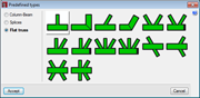
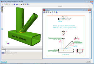
CYPE-Connect was implemented in the previous program version (2014.f). It was created to check, design and generate welded and bolted connections with rolled steel I-sections. The types of joints that could be designed in this first version are those included in the Joints I, Joints II, Joints III and Joints IV modules. ![]()
Now, with the 2014.g version, the types of joints corresponding to Joints V – Flat trusses with hollow structural sections have been implemented in CYPE-Connect. Using this module in CYPE-Connect, the program designs, checks and generates the detailing of coplanar joints composed of hollow structural sections, which are most commonly used in flat trusses with circular hollow sections, rectangular hollow sections, square hollow sections and hollow sections composed of two channels welded in a box. The 2014.g has yet to include joint types consisting of a “Splice connection of two aligned hollow sections using bolted front plate”. These will be implemented in an upcoming version.
CYPECAD MEP
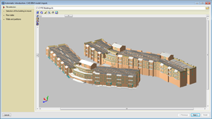
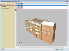
IFC file composed of several buildings
As of the 2014.g version, when CYPECAD or CYPECAD MEP import a file in IFC format (Industry Foundation Classes) composed of several buildings, the import assistant allows users to select the building which is to be imported using the option: “Selection of the building to import”. This option is deactivated when the IFC is created as a single building.
Novo Cypeterm (CYPECAD MEP for Portugal)
The 2014.g version of Novo Cypeterm includes the following improvements:
- Report justifying the calculation of the internal thermal energy
This report justifies the calculation of the internal thermal energy of the occupied units of the building units which can be obtained for each occupied unit or for a group of them. - Verification of section 2.2 point 2 of the Portaria n.°349-B/2013
Maximum thermal transmission coefficient checks for flat beam-column thermal bridge zones have been added.
Return to the 2014 version download area
Tel. USA (+1) 202 569 8902 // UK (+44) 20 3608 1448 // Spain (+34) 965 922 550 - Fax (+34) 965 124 950