
![]()
The 2014.f version of CYPE programs contains important new features and improvements which can be explored in more detail by clicking on the links below.
- New modules and programs
- CYPE-Connect (Structures)
- Radiant and cooling ceiling (Building services)
- Ceiling types and installation components
- Data introduction
- Installation design
- Bill of quantities of the installation
- Drawings and reports
- Required user licence permits
- Novo Cypeterm (Building Services – Portugal)
- Cumprimento REH (Management – Portugal)
- Prestazioni energetiche degli edifici (Management – Italy)
- Code implementation and improvements in its application
- CYPECAD
- CYPECAD MEP
- Return to the 2014 version download area
New modules and programs
CYPE-Connect (Structures)
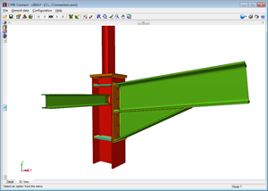
CYPE-Connect is a program to check, design and generate the detailing of welded or bolted steel connections composed of rolled steel I sections.
CYPE-Connect is available in the Structures group of the main CYPE program menu.
The types of joints that are designed are those included in the following joints modules (modules available for use with CYPECAD and Metal 3D), which were implemented in previous program versions:
- Joints I. Welded. Warehouses with rolled and welded steel I sections
- Joints II. Bolted. Warehouses with rolled and welded steel I sections
- Joints III. Welded. Building frames with rolled and welded steel I sections
- Joints IV. Bolted. Building frames with rolled and welded steel I sections
In an upcoming version of CYPE-Connect, the types of joints corresponding to the Joints V. Flat trusses with hollow structural sections module will be included.
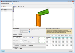
Using a data introduction assistant, users select the design code, load combination, loadcases and design options (bolted or welded joint, bolt selection – prestressed or ordinary bolts -, stiffeners). All the data introduced using the assistant can be modified at any time.
Users can select a joint within the admissible types of each joints module or introduce the connection bars manually. The program will only check and design the connections which form part of the admissible joint types. Forces acting on the node have to be defined by loadcase, the type and series of each bar also have to be defined.
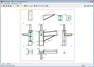
Once the data has been introduced, users can select the option to analyse and design the joint. The program automatically analyses and designs the joint so all the limitations established by the selected code and users are met. Once the design process has concluded, a detailed report of all the checks which have been carried out can be obtained, as well as the on-screen detailing of the joint and corresponding drawing.
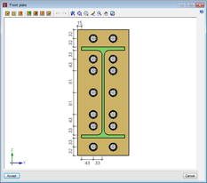
CYPE-Connect carries out the same design as CYPECAD and Metal 3D. The new feature of CYPE-Connect which makes it different to the other two programs is that users can edit the designed joint, modify the dimensions and arrangements of the plates, welds and bolts, and finally tell the program to check the joint connections with the changes that have been carried out.
During the check, the program verifies if the connections of the joint meet all the requirements established by the code. Once the joint has been checked, a detailed report can be obtained with all the checks that have been carried out.
Therefore CYPE-Connect allows users to personalise a joint and check that the modifications that have been carried out meet the requirements of the selected code, as well as providing a complete and detailed report of all the checks that have been carried out.
To be able to use CYPE-Connect, users must have a user licence permit to use at least one of the joints modules indicated above. The program analyses, designs and checks the types of joints contained in the modules included in the user license.
A webpage will shortly be available where more details will be provided on the program.
Radiant and cooling ceiling (Building services)
Radiant and cooling ceiling is a CYPECAD MEP module integrated in the Air conditioning tab. The module has been conceived to design invisible air conditioning systems using radiant and cooling ceilings of two types: modular technical dropped ceilings and continuous dropped ceilings.
Ceiling types and installation components
The radiant and cooling ceiling air conditioning systems are invisible air conditioning systems which condition precincts using hot/cold water circuits integrated in their ceilings.
Users can choose between the following systems:
- Continuous dropped ceiling systems
- Modular technical dropped ceiling systems
In both cases, the water circuits are located inside the ceiling panels and are connected to one another, making up panel circuits, which are connected to water distribution manifolds. These manifolds, which contain regulation and control systems, will be connected to the production equipment.
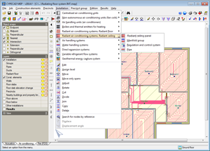
Data introduction
As occurs with radiant floors, radiant ceilings are a construction characteristic of the precinct, and so, before the ceiling panels of the installation are introduced, the radiant ceiling has to be defined in the cladding of the ceiling of the precinct (Precincts > Ceiling cover). As occurs with radiant floors, the ceiling that has been defined is taken into account in the various analyses carried out by the application: thermal insulation analysis, acoustic insulation analysis, thermal loads...
The different elements making up the radiant ceiling air conditioning installation are available in the “Radiant air conditioning systems. Radiant ceiling” option (Installation menu of the Air conditioning tab). These are:
- Radiant ceiling panel
- Manifold set
- Regulation and control system (shared with radiant floor systems)
- Pipe (discharge and return)
The following points must be taken into account in the panel arrangement of either system:
- Continuous ceiling system
- The program considers the areas in which no radiant ceiling panels have been provided as non-active areas.
- The panels are connected in parallel.
- Modular ceiling system
- Contains active and blind (non-active) panels.
Since these panels are of a fixed size and cannot be divided, users must introduce both the active and blind panels, so the program can compute the correct quantities of the installation.
In zones where a complete panel can be placed (or where users have not placed any panels), the program provides a dropped ceiling type that was selected in the dialogue box where the properties of the selected system were defined. - Groups of panels can be connected in series and then interconnected in parallel. The maximum number of panels that can be connected in series depends on the selected model.
- Contains active and blind (non-active) panels.
The radiant and cooling ceiling systems must be connected with a reverse return circuit to balance the installation. Therefore, users have to introduce the discharge and return of each circuit separately. The program represents the discharge and return spans differently to help users with their introduction.
Installation design
Once users have defined the type of radiant ceiling in the cladding properties of the precinct ceilings (Precincts > Ceiling cover), an initial analysis is recommended before introducing the installation. Once this initial analysis has concluded, CYPECAD MEP will guide users on which installation will have to be installed in each precinct depending on its conditions and the type of system that has been selected. The program will display:
- The number of panels that is required to cover the maximum sensible summer load
- The maximum number of panels per circuit
- The maximum number of panels connected in series, if a modular ceiling system is to be placed
Once the installation has been introduced, the analysis carried out by the program is based on the behaviour curves defined by the manufacturer of each type of panel. This way, once the power offered by each panel is known, depending on the conditions of the precinct and the production equipment, the program establishes the required discharge temperature to cover the maximum sensible thermal load for cooling and heating, bearing in mind the conditions to avoid condensation and the allowable temperature at the surface of the ceiling (17ºC for cooling and 32ºC for heating).
Bill of quantities of the installation
The program measures the quantities and provides the prices (only applicable to those countries for which the Price generator is available) of all the distribution systems and accessories required to install the radiant ceiling system, if these systems have been imported using the Price generator.
Drawings and reports
The program also provides drawings and reports of the designed installation.
Required user licence permits
Users are required to have the Radiant and cooling ceiling module as well as the additional and required permits, which must be included in the user licence to analyse and design an air conditioning installation using a radiant and cooling ceiling, which depend on the complexity of the installation. As these are systems which have been conceived for cooling, users will be required to have, at least, the Cooling thermal loads module. If, the ceiling is also to be a heating ceiling, to optimise the installation, the Heating thermal loads module will also be required. These systems are also water distribution systems, and so the Water pipes for air conditioning module and the permits for the production equipment used in the installation.
Novo Cypeterm (Building Services – Portugal)
The 2014.f version of CYPECAD MEP for Portugal includes the Novo Cypeterm tab. The aim of this software is to aid designers to ensure the energy efficiency requirements for residential buildings established in the REH (Regulamento de Desempenho Energético dos Edificios de Habitação) are met.
The following standards are contemplated by Novo Cypeterm so the REH is complied with:
- EN ISO 6946
- EN ISO 13370
- EN ISO 10077-1
- EN ISO 13789
- EN ISO 14683
- EN ISO 10211
- EN ISO 10456
Novo Cypeterm contains a tool which allows the calculated parameters to be exported to the new Cumprimento REH program, also implemented in the 2014.f version. These include areas, volumes, thermal transmittance coefficients, which are obtained based on the selected construction solutions, thermal transmittance values of the detected thermal bridges, which are then analysed numerically using two-dimensional finite elements, internal thermal capacity of the zone, solar radiation obstruction factors, loss reduction...
Cumprimento REH (Management – Portugal)
This new program can be accessed from the main CYPE program menu when the software has been installed in Portuguese and is located within the Documentação program group. The aim of this software is to aid designers to ensure the energy efficiency requirements for residential buildings established in the REH (Regulamento de Desempenho Energético dos Edificios de Habitação) are met.
This free software can be executed independently from other CYPE programs and allows users to establish the energy efficiency of buildings, by defining parameters and methods indicated in the code in force.
The parameters are introduced manually in Cumprimento REH. To obtain these parameters, users must use Novo Cypeterm, which carries out an automatic calculation by analysing the three-dimensional model of the building.
Prestazioni energetiche degli edifici (Management – Italy)
This program can be accessed from the main CYPE program menu when the software has been installed in Italian and is located within the Documentazione program group. The aim of this software is to aid designers to ensure the energy efficiency requirements for buildings established in the UNI/TS 11300-1, UI/TS 11300-2 and UNI/TS 11300-4 are met.
This free software can be executed independently from other CYPE programs and allows users to establish the energy efficiency of buildings, by defining parameters and methods stated in the indicated codes.
The parameters are introduced manually in Prestazioni energetiche degli edifici. To obtain these parameters, users must use “CYPECAD MEP”, which carries out an automatic calculation by analysing the three-dimensional model of the building and exports the results to the new “Prestazioni energetiche degli edifici” program.
Code implementation and improvements in its application
Concrete code
SP 63.13330.2012 (Russia)
Concrete and reinforced concrete. Construction. Updated edition SNIP 52-01-2003. Moscow 2012.
Implemented in CYPECAD, Metal 3D and Continuous beams.
For this code, CYPECAD, Metal 3D and Continuous beams allow for:
- Additional loadcases to be added for special frost loads.
- A percentage of the load to be defined as long-term loading, for live load and snow loadcases.
- The advanced beam editor (CYPECAD) to be used

- The advanced column editor (CYPECAD) to be used
If the Russian concrete code is used together with its corresponding seismic code (СНиП II-7-81 – implemented in the 2014.b version), the ductility reinforcement criteria and capacity design criteria for bending of concrete columns are taken into account.
Cold-formed steel code
AS 4600:2005 (Australia)
Australian StandardTM Cold-formed steel structures.
Implemented in CYPECAD and Metal 3D.
NZS 4600:2005 (New Zealand)
New Zealand StandardTM Cold-formed steel structures.
Implemented in CYPECAD and Metal 3D.
Loads on structures. Seismic loads
NTC 2004 (Mexico)
Normas Técnicas Complementarias para diseño por sismo.
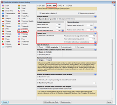
This code was already implemented in CYPECAD and Metal 3D as of previous versions. Now, with the 2014.f version the option offered by appendix A of the code has been implemented, whereby for the seismic design of structures located in zones II and III, the effects of the site and ground-structure interaction can be taken into account explicitly.
To apply this possibility, an option “Interacción suelo-estructura” has been implemented in the “Seismic zone” section of the "Code for the calculation of seismic loading” dialogue box (Job > General data > Select “With seismic loading” in the Loads section > Select Mexico and the NTC 2004). This option allows users to define the values of the “Periodo dominante más largo del terreno (Ts)” and the “Factor reductivo por amortiguamiento”, and consider an overresistance factor, if necessary.
СНиП II-7-81* (Russia). Ductility reinforcement criteria and capacity design criteria
Construction in seismic regions.
This code was already implemented in CYPECAD and Metal 3D in the 2014.b version. Now, with the 2014.f version, the ductility reinforcement criteria and capacity design criteria for bending are taken into account when this code is used together with the Russian concrete code SP 63.13330.2012 (implemented in this version).
CYPECAD
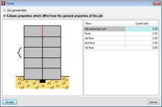
Cover of concrete columns by floor and by column
Users now have the option to define specific concrete column covers different to those defined in the general data of the job for each column span (Column Definition tab > Introduction > Columns, shear walls and starts > Cover > select a column). Within the dialogue, a new option has been added: “Column properties which differ from the general properties of the job”.
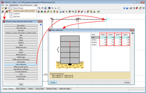
Column fixity coefficients in two directions
As of previous versions, CYPECAD allows users to modify the fixity coefficient at the top (head) and bottom (base) of each column span (Column Definition tab > Introduction > Columns, shear walls and starts > Fixity coefficients > Select a column).
Now, with the 2014.f version, these fixity coefficients can have different values in the X-direction and Y-direction of the local axes of the column.
CYPECAD MEP
Air conditioning. Radiant and cooling ceiling
The 2014.f version includes the new “Radiant and cooling ceiling” module for CYPECAD MEP, integrated in the Air conditioning tab. The module has been conceived to design invisible air conditioning systems using radiant and cooling ceilings of two types: modular technical dropped ceilings and continuous dropped ceilings.
More information can be found in the “Radiant and cooling ceiling” section on this webpage.![]()
3D view in the side menu
A 3D view of the floor currently being edited can be activated in the left lateral menu within all the tabs of CYPECAD MEP. This allows users to quickly view the construction elements that are being introduced and the installation corresponding to the tab within which the work is being carried out.
Thermal analysis for France
EDIBATEC database
The EDIBATEC database has been implemented in the “Étude thermique” tab of CYPECAD MEP for France. Using this tool, different product data is introduced and selected more easily. As of the 2014.f version, users can consult and import the following from this database:
- Deposits
- Generators
- Timber boilers
- Heaters
Thermal analysis for Italy
Select systems to carry out the thermal analysis
The 2014.f version includes the possibility to select the following systems and improvements so they may be taken into account when the program carried out the thermal analysis:
- Cogeneration systems with Stirling engine
- Heat pump systems with activation by endothermic engine
- Generic photovoltaic collectors
- Shade factors for photovoltaic and thermal collectors
Export to the new program “Prestazioni energetiche degli edifici”
CYPECAD MEP now has a new tool which allows users to export the calculated parameters to the new program: Prestazioni energetiche degli edifici, also implemented in the 2014.f version (only available for CYPECAD MEP in Italian).
Return to the 2014 version download area
Tel. USA (+1) 202 569 8902 // UK (+44) 20 3608 1448 // Spain (+34) 965 922 550 - Fax (+34) 965 124 950