
(20th September 2013)
![]()
- Code implementation and improvements in its application
- CYPECAD
- Seismic analysis. Fundamental period of the structure with user values for CFE 2008 and NTC 2004 Mexican design codes
- Advanced beam editor
- Representation of the reinforcement when editing openings
- Improvements in the edition of beam assembly reinforcement tables
- Averaging of required reinforcement areas in slabs
- CYPECAD MEP
- Thermal analysis for Italy
- Air conditioning
- Heat recovery (thermal and hygrometric) in the definition of precincts
- Hygrometric efficiency in the definition of heat recovery ventilators
- Radiant and cooling floors. Temperature limit considered in the analysis
- Export to IFC
- Return to Download Area
Code implementation and improvements in its application
Loads on structures. Seismic loads
CFE 2008 (Mexico) and NTC 2004 (Mexico)
- CFE 2008 (Mexico)
Manual de Diseño de Obras Civiles. Diseño por Sismo
- NTC 2004 (Mexico)
Normas Técnicas Complementarias para Diseño por Sismo
These codes were already implemented in CYPECAD and Metal 3D as of previous versions. Now, in the 2014.c version, CYPECAD offers two options to indicate the value of the Fundamental period of the structure (used to calculate the base shear):
- In accordance with the code (only way possible in previous versions)
- User specified (implemented in the 2014.c version)
More information can be found in the section on: “Seismic analysis. Fundamental period of the structure with user values for CFE 2008 and NTC 2004 Mexican design codes” in the new features of CYPECAD of this webpage.
CIRSOC 103-2005 (Argentina)
Normas Argentinas para Construcción Sismorresistente. Parte II: Construcciones de Hormigón Armado.
This code was already implemented in CYPECAD as of the 2013.l version in order to be able to use the Reinforcement ductility criteria and the Capacity design criteria for seismic design which are to be used with the concrete code: CIRSOC 201-2005 (Reglamento Argentino de Estructuras de Hormigón).
Now, for the 2014.c version, the following checks have been included:
- Compliance with article 2.2.9.2
- For the capacity check of concrete columns, the design axial force specified in article 2.3.5 is used
Please recall that users do not select the CIRSOC 103-2005 code to be applied. The combination of the CIRSOC 201-2005 concrete code together with seismic code CIRSOC 103-1991 (current seismic code in force in Argentina) or together with seismic code CIRSOC 103-2008 (project seismic code which will substitute CIRSOC 103-1991) implies the reinforcement ductility criteria and capacity design criteria for seismic design of CIRSOC 103-2005 be applied.
CYPECAD
Seismic analysis. Fundamental period of the structure with user values for CFE 2008 and NTC 2004 Mexican design codes
 CYPECAD allows users to define the Fundamental period of the structure (used to calculate the base shear) in two ways:
- Based on the code (only way possible in previous versions)
- Specified by the user (implemented in the 2014.c version)
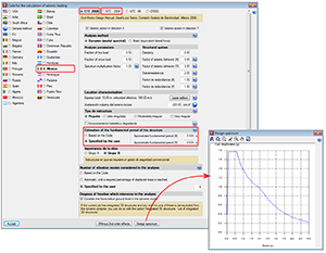
Either of the two options can be selected in the section Estimation of the fundamental period of the structure within the Code for the calculation of seismic loading dialogue box (General data ˃ Select “with seismic loading” from the “Loads” section ˃ select Mexico as the country and CFE 2008 or NTC 2004).
The value of the fundamental period of a building must be obtained based on the properties of its seismic resistance system, in the direction being considered, in accordance with structural dynamic principles. Alternatively, most seismic codes allow for the fundamental period to be estimated:
- Using empirical formulas provided within their articles
- Using other methods, as long as these are adequately sustained analytically or experimentally
The estimated fundamental period is applied in the calculation of the static shear at the base of the structure (base shear) which:
- Adjusts the dynamic results to minimum values prescribed in the code, if the dynamic method is applied
- Generate the distribution of the equivalent static lateral forces, if the static method is applied
Article 3.3.5.1 of the CFE 2008 code establishes the calculation of the base shear force by taking the bottom period limit of the plateau of the design spectrum (Ta) as the estimated fundamental period; and article 8.1 of the NTC-2004 code takes any period which coincides with the design spectrum plateau (Ta ≤ T ≤ Tb).
The indicated values are limits established in the codes that can be used in the absence of more precise data. If users have values of the fundamental period which are more adjusted to their structure (calculated using their methods or using software such as CYPECAD, which calculates the fundamental period of the structure in each direction – the values can be consulted after the analysis in the “Justification of seismic action report”: File ˃ Print job reports), they may specify them by selecting the Specified by the user option, located in the Code for the calculation of seismic loading dialogue box, as has been indicated previously.
Advanced beam editor
 Representation of the reinforcement when editing openings
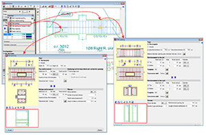
A transverse section of the beam is represented in the zone of the opening with the reinforcement arrangement, within the edition or introduction dialogue boxes of vertical or horizontal beam openings (edit a beam from the Results tab of CYPECAD using the Advanced beam editor ˃ select the ![]() button of the editor ˃ select any of the edition or introduction options for openings).
button of the editor ˃ select any of the edition or introduction options for openings).
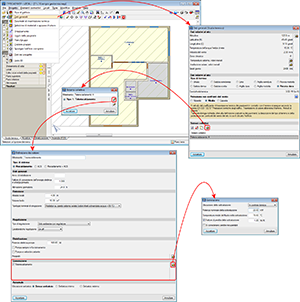
Improvements in the edition of beam assembly reinforcement tables
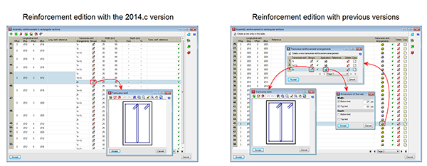
The edition of beam assembly reinforcement tables has been improved (Job ˃ General data ˃ By position button ˃ Beam options ˃ Beam reinforcement tables ˃ select any of the three assembly reinforcement tables). Now, the creation of new table entries, the creation of new stirrup arrangements, the visualisation and modification of the width and depth intervals for which each reinforcement arrangement is available in the table, are carried out in the same dialogue box without successive windows appearing.
Please recall that the edition of the reinforcement tables that has been indicated is only available for codes which can use the Advanced beam editor.
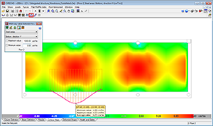
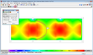
Averaging of required reinforcement areas in slabs
Two new options have been implemented in the Contour Maps tab so the average values of the forces, design forces or steel areas of flat slabs and waffle slabs can be consulted. The mid-way value between two points or average values of a strip can be viewed in either reinforcement direction of the slab.
 CYPECAD MEP
Thermal analysis for Italy
Selection of heating systems with District Heating (Teleriscaldamento) to carry out the thermal analysis
The 2014.c version includes the possibility to select heating systems using District Heating; so that the primary energy demand and efficiency of the heating systems of the building are taken into account.
Users can introduce the District Heating system within the Definizione dei sistemi dialogue box (Studio termico tab ˃ Datigenerali ˃ edit or add in the Sistemi collettivi section ˃ edit or create type ˃ select a District Heating type in the Generazione section of the Definizione dei sistemi dialogue box). These systems can also be used in an automatic manner for a zone of the building. To do so, zones must be defined in the building (Zone menu) and assign the system to the chosen zone within the “Sistemi autonomi” section.
Using the edit button of the Generazione section of the Definizione dei sistemi dialogue box, users can define the data of the selected heating system.
The results can be consulted in the Fabbisogni di energia primaria e rendimenti per la climatizzazione invernale del sistema edifice-impianto (Studio termico tab ˃ File ˃ Stampare ˃ Relazioni del prgetto) report provided by the program.
 Air conditioning
Heat recovery (thermal and hygrometric) in the definition of precincts
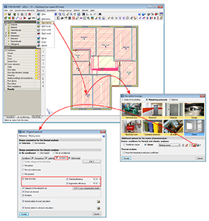
As of the 2014.c version, CYPECAD MEP users can define the thermal and hygrometric efficiency values of ventilation systems with heat recovery in the internal conditions of the precincts (within the ventilation section). This way, the effect of the ventilation systems will be seen in the thermal load calculation results without having to introduce the installation.
The thermal efficiency of the ventilation system with heat recovery can be defined for both the air conditioned precincts and for those which are only heated, whilst the hygrometric efficiency can only be defined for air conditioned precincts.
If, as well as defining the properties of the ventilation system with heat recovery in the description of the precincts, users also introduce the installation, the program checks that the values which have been introduced correspond with the values defined for the heat recovery ventilator.
Hygrometric efficiency in the definition of heat recovery ventilators
The possibility to define the hygrometric efficiency (for the recovery of latent heat) has been added.

Radiant and cooling floors. Temperature limit considered in the analysis
As of the 2014.c version, CYPECAD MEP considers the flow temperature of the generating systems to be the temperature limit of the radiant floor system. This way, the thermal emission of the circuits of the radiant floor will be reduced if the flow temperature of the production system is less than (or greater than, in the case of cooling floors) that required by the system of the radiant floor in accordance with the code.
Export to IFC
Local measurement units different to the global units of the project
Some IFC format file entities generated by CYPECAD MEP may have properties whose local measurement units are different to the global units of the project. For example, the internal roughness coefficient of the pipes of radiant floors is exported in mm and not in the global units of the project (m).
Tel. USA (+1) 202 569 8902 // UK (+44) 20 3608 1448 // Spain (+34) 965 922 550 - Fax (+34) 965 124 950