
New features and download of the 2013.j version
(15 February 2013)
![]()
- New modules
- Improvements in code application
- Concrete code
- Loads on structures. Seismic loads
- Capacity design criteria for seismic design of concrete columns and beams with the NSR-10 (Colombia) code
- NBDS-2006 (Bolivia)
- NC 46:1999 (Cuba)
- NC 46:1999 (Cuba); NSR-10 (Colombia)
- NCh433.Of1996 (Chile)
- Thermal insulation
- New features in CYPECAD
- Capacity design criteria for seismic design of concrete columns and beams with the NSR – 10 (Colombia) code
- Advanced beam editor of CYPECAD
- Position of the cursor in the areas graph
- Automatic change of the areas graph depending on the type of reinforcement that is being edited
- Consult span deflections
- Extended and improved error information
- Maintenance of the active option within the editor when another frame is selected
- Maintenance of the floating menu positions
- Bar anchorage in accordance with user defined options
- Representation of confinement zones
- Improvements of drawings with reinforcement detailing only in tables
- Export to IFC
- Punching shear verification
- New features in CYPECAD MEP
- Export to IFC from CYPECAD MEP
- Improved representation of wall openings
- Improvements in IFC export for more air conditioning equipment
- Air conditioning and thermal analysis
- New features in Arquimedes and Job Control
- New columns with partial payments in the Decomposition tree window
- Customised column names in the Decomposition tree window
- Reading of the user license key file (clv)
- Return to the 2013 version download area
New modules
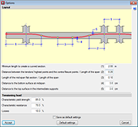
Post-tensioned concrete slabs for buildings (CYPECAD)
A new module: Post-tensioned concrete slabs for buildings has been included in the 2013.j version of CYPECAD, which has been created to design the passive reinforcement of post-tensioned slabs before calculating the forces of the post-tensioned tendons (bonded or unbonded) and whose properties have been introduced by program users.
Post-tensioned technology has different degrees of acceptance in many countries. CYPE has designed this module given the increasing demand of CYPECAD users to have a tool which can design post-tensioned concrete slabs.
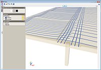
The Post-tensioned concrete slabs for buildings module allows users to introduce the path of the tendons, their definition, the post-tensioned forces and percentage loss. The program generates a post-tensioned loadcase in which the deviation loads produced by the path of the tendons are introduced. During the slab reinforcement design stage, and if the tendons have been defined as bonded, if there is any capacity excess or shortage regarding the contribution of the active reinforcement, it will be taken into account to establish the passive reinforcement.
More information on this new CYPECAD module is available here: Post-tensioned concrete slabs for buildings
Improvements in code application
Concrete code
ABNT NBR 6118:2007 (Brazil)
Norma Brasileira ABNT NBR 6118 (2007). Projeto de estruturas de concreto - Procedimiento.
Implemented in Punching shear verification. This code was already implemented for other CYPE programs.
NSR-10 (Colombia) (Título C - Concreto estructural)
Reglamento Colombiano de Construcción Sismo Resistente NSR-10. Título C - Concreto estructural.
Implemented in CYPECAD, Metal 3D, Stairs, Foundation elements, and Continuous beams.
CYPECAD's advanced column and beam editors are also available with this code.
Loads on structures. Seismic loads
Capacity design criteria for seismic design of concrete columns and beams with the NSR-10 (Colombia) code
More information on the implementation of capacity design criteria for the seismic design of concrete columns and beams can be found in the Capacity design criteria for seismic design of concrete columns and beams with the NSR-10 (Colombia) code section of the new features of CYPECAD on this webpage.
NBDS-2006 (Bolivia)
Norma Boliviana de Diseño Sísmico (2006). Título A. Análisis y diseño sismo resistente.
Implemented in CYPECAD and Metal 3D.
NC 46:1999 (Cuba)
Construcciones sismo resistentes. Requisitos básicos para el diseño y la construcción.
This code was already implemented in CYPECAD and Metal 3D as of previous versions. It is used in CYPECAD together with the ACI 318M-08 (USA – International) concrete code.
As of the 2013.j version, if users select the ACI 318M-08 (USA International) code and combine it with this seismic code, they can then use CYPECAD’s advanced column editor.
NC 46:1999 (Cuba); NSR-10 (Colombia)
Improvements have been implemented in the following seismic codes:
- NC 46:1999 (Cuba)
Construcciones sismo resistentes. Requisitos básicos para el diseño y construcción.
- NSR-10 (Columbia)
Reglamento Colombiano de Construcción Sismo Resistente (2010).
These codes were already implemented in CYPECAD and Metal 3D, as of previous versions. They are used in CYPECAD together with the ACI 318M-08 (USA-International) code.
As of the 2013.j version, if users select the ACI 318M-08 (USA International) code and combine it with either of the previously mentioned seismic codes, they can then use CYPECAD’s advanced beam editor.
If the NSR-10 (Colombia) code is combined with the NSR-10 concrete code (Colombia – Título C – Concreto estructural), users can also use CYPECAD’s advanced beam editor.
NCh433.Of1996 (Chile)
Norma Chilena Oficial. Diseño Sismico de Edificios.
This code was already implemented in CYPECAD and Metal 3D, as of previous versions. As of the 2013.j version, if this code is used together with the NCh430.Of2008 concrete code, users can also use CYPECAD’s advanced beam editor.
Thermal insulation
EN ISO 14683 (International)
Thermal bridges in building construction. Linear thermal transmittance. Simplified methods and default values.
Implemented in the Air Conditioning tab of the international version of CYPECAD MEP.
New features in CYPECAD
Capacity design criteria for seismic design of concrete columns and beams with the ACI 318M-08 (USA) code
The 2013.e, 2013.g, 2013.h and 2013.i versions of CYPECAD implemented the capacity design criteria for bending and shear for the seismic design of concrete supports, and capacity design criteria for shear for the seismic design of concrete beams in accordance with the following codes: ACI 318M-08 (USA – International), EHE-08 (Spain), NCSE-02 (Spain) and IS 13920:1993 (India).
Now, implemented for the 2013.j version, are the capacity design criteria for bending and shear for the seismic design of concrete supports, and capacity design criteria for shear for the seismic design of concrete beams in accordance with the NSR – 10 (Colombia) code.
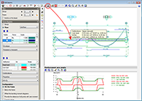
Advanced beam editor of CYPECAD
 Position of the cursor in the areas graph
The position of the cursor is represented in the areas graph of the frame by means of a vertical line when the cursor is located in the zone where the reinforcement details of the frame can be viewed, and if any of the following beam editor options have been activated:
- Introduce assembly reinforcement
- Introduce additional reinforcement bars
- Introduce skin reinforcement
- Introduce stitching reinforcement
- Introduce overlaps
- Edit (longitudinal reinforcement)
- Edit shear reinforcement
- Divide shear reinforcement spans
This vertical line moves at the same time as the cursor is displaced over the reinforcement details, and aids in recognising the zone in which the work is being carried out.
This feature is also available when the option “Consult values” (of the represented force graphs) is marked, which is located in the “Configuration” section in the lateral menu of the beam editor.
Automatic change of the areas graph depending on the type of reinforcement that is being edited
The reinforcement area representation changes automatically and displays the longitudinal reinforcement area when any of the longitudinal reinforcement edition options are selected (![]() button in the top part of the editor). Similarly, the transverse reinforcement areas are automatically displayed when any of the transverse reinforcement edition options are used (
button in the top part of the editor). Similarly, the transverse reinforcement areas are automatically displayed when any of the transverse reinforcement edition options are used (![]() button in the top part of the editor).
button in the top part of the editor).
 Consult span deflections
A new option, Consult deflections in spans (represented by the ![]() button in the top part of the beam editor), which displays the deflection values of the selected frame span. This tool provides the same information as is obtained using the “Beam/wall information” option in the “Beams/Walls” menu of CYPECAD.
button in the top part of the beam editor), which displays the deflection values of the selected frame span. This tool provides the same information as is obtained using the “Beam/wall information” option in the “Beams/Walls” menu of CYPECAD.
The Consult deflections in spans option lets users know the deflection of a span without having to leave the beam editor, and takes into account any changes users may have carried out on the frame reinforcement.
The deflection is not calculated each time users change the reinforcement. Users must bear in mind that the deflection calculation process is quite laborious and, if the program were to update the values each time the reinforcement is modified, the reinforcement edition process would be, unnecessarily, very slow. Hence, when the Consult deflections in spans option is used, once changes in the frame reinforcement have been carried out, the program indicates that the span deflections have to be recalculated and asks the user if he/she wishes to continue. If the answer is affirmative, the span deflections will be recalculated and displayed on screen. If the answer is negative, the program will not display the deflection information.
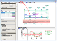 Extended and improved error information
Up until the previous version (2013.i), the Show error messages option (from the Show error messages dialogue that opens when the ![]() button is selected in the top part of the editor) displayed all the error messages due to the introduced reinforcement (zones of the frame without reinforcement, bars with bending shape errors...). As of the 2013.j version, the Show error messages option displays all the errors in the tool-tip that appears when a span containing errors is selected. The information shown is the same as that provided with the “Beam errors” option from the “Beams/Walls” menu of CYPECAD, but with the added list of checks that have been failed, if any are found.
button is selected in the top part of the editor) displayed all the error messages due to the introduced reinforcement (zones of the frame without reinforcement, bars with bending shape errors...). As of the 2013.j version, the Show error messages option displays all the errors in the tool-tip that appears when a span containing errors is selected. The information shown is the same as that provided with the “Beam errors” option from the “Beams/Walls” menu of CYPECAD, but with the added list of checks that have been failed, if any are found.
The location points of the errors are visible with all the options of the beam editor, unless users deactivate them (using the “Hide all errors” option in the dialogue box that opens using the ![]() button).
button).
The error information may not be up to date (for example, if the reinforcement of the frame has been modified), in which case, this is indicated in the tool-tip that displays the error information. The errors are not updated automatically after each modification for the same reason as with the deflection calculation, indicated in the previous section. So users can update the error information when they deem adequate (for example, once the reinforcement has been modified several times), the option: Update error information has been implemented, which is represented by the ![]() button (located to the left of the
button (located to the left of the ![]() button).
button).
Maintenance of the active option within the editor when another frame is selected
The following options of the beam editor, remain active when the frame being edited is modified (if possible):
 U.L.S. and S.L.S. checks at the worst case point
 U.L.S. and S.L.S. checks at a point
 Consult deflections in spans
These options are only deactivated when the required conditions for their operation are not present (for example: if a U.L.S. check option is active for a frame and the user moves to another whose reinforcement is not defined).
These improvements allow for a quicker check of the frames in the editor, because the number of mouse-clicks are reduces when moving from one frame to another.
Maintenance of the floating menu positions
The floating menus that appear using some of the beam editor options are maintained where the user last placed them.
Bar anchorage in accordance with user defined options
When introducing hook anchorages using the Advanced beam editor, without specifying the length (Longitudinal reinforcement button ![]() > Edit
> Edit ![]() > select the end of the reinforcement bar), the program takes into account if the option in CYPECAD: The depth minus the cover, with a maximum of, is activated so to calculate the length of the top or bottom anchorage lengths (Job > General data > By position button in Steel in bars
> select the end of the reinforcement bar), the program takes into account if the option in CYPECAD: The depth minus the cover, with a maximum of, is activated so to calculate the length of the top or bottom anchorage lengths (Job > General data > By position button in Steel in bars ![]() > Beam options > Design/ Code checks > Top reinforcement or Bottom reinforcement button > Anchorage length > The depth minus the cover, with a maximum of).
> Beam options > Design/ Code checks > Top reinforcement or Bottom reinforcement button > Anchorage length > The depth minus the cover, with a maximum of).
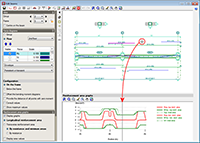
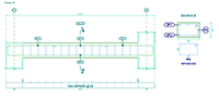
Representation of confinement zones
A new option Show confinement zones (located in the View section in the lateral menu of the beam editor) has been implemented. Upon activating this option, the limits of the confinement zones of the transverse reinforcement are represented with blue vertical lines on screen where the reinforcement detailing of the concrete frames is displayed. This option is only visible if an analysis with earthquake loading has been carried out.
 Improvements of drawings with reinforcement detailing only in tables
In the 2013.h version, the option to provide the Reinforcement details only in the table, was implemented. Now, in the 2013.j version, the representation of the text indicating the positions of the bars, has been improved for these types of drawings. The positions are surrounded by an oval frame for both elevation and transverse sections views. Additionally, the labels of the transverse sections have been simplified in accordance with what is customary in the countries that use this type of detailing (American detailing).
Export to IFC
As of the 2013.j version, the export to IFC format (Industry Foundation Classes) now includes the tendons of the post-tensioned slabs that can be introduced in CYPECAD thanks to the new Post-tensioned concrete slabs for buildings module that has also been implemented with this version.
Punching shear verification
Implementation of the ABNT NBR 6118:2007 (Brazil) concrete code
A new program, Punching shear verification, was implemented in the 2013.e version. This program, which can be executed from the Structural elements group of the main CYPE program menu, checks the Failure Limit State of concrete for punching shear in flat and waffle slabs exposed to concentrated loads from rectangular or circular supports. The program can check slabs with or without transverse punching shear reinforcement, takes into account the presence of openings or lightweight zones in the slab, and the position of the supports (internal, edge or corner).
Now, for the 2013.j version, the ABNT NBR 6118:2007 (Brazil) code has been implemented in Punching shear verification, which was already available in other CYPE programs. More information on the implemented codes can be seen in the Implemented codes section of the Punching shear verification page.
New features in CYPECAD MEP
Export to IFC from CYPECAD MEP
Improved representation of wall openings
The representation of wall openings, generated when exporting to IFC from CYPECAD MEP, has been improved.
Improvements in IFC export for more air conditioning equipment
Improvements were made in the previous version (2013.i) concerning the export of different air conditioning installations and centralised air conditioning units (except Rooftops). These elements could already be exported to IFC format (Industry Foundation Classes) as of previous versions, in accordance with the standards of the format. The improvements consisted in including the materials, colours, appropriate assigning of the IFC entity and including the technical properties of the selected manufacturers.
Now, in the 2013.j version, these improvements have been implemented in the export to IFC for the following air conditioning equipment:
- Rooftops
- Fan coils
- Direct expansion systems
- Variable refrigerant flow systems
Air conditioning and thermal analysis
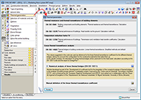 Characteristic heat transmission parameters
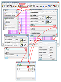
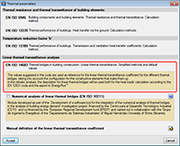
A new dialogue box has been implemented to manage the characteristic heat transmission parameters; the Thermal parameters dialogue box. This box can be accessed from the Air conditioning tab (Job > Thermal parameters).
This new dialogue box offers users information on the codes applied when analysing the various characteristic heat transmission parameters and allows users to manage the different options of by the program for their analysis. The appearance of this dialogue box depends on the on the language which CYPECAD MEP has been executed with (English, French, Portuguese, Portuguese for Brazil, Spanish, Spanish for Argentina and Spanish for Mexico). For the Catalan version, the dialogue box has the same aspect as with the Spanish version.
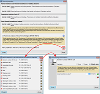
In previous versions, users could manage, in a collective manner for the detected types of linear thermal bridges, the type of analysis or which heat transmission coefficients were to be applied at the edges of these thermal bridges. Now, with the Thermal parameters dialogue box, users can configure and specify the analysis method to calculate the linear transmittance of each linear thermal bridge.
Amongst the options included in the Thermal parameters dialogue box is the option to activate the design using the numerical analysis of linear thermal bridges and the option to define user values for the various types of linear thermal bridges.
As of previous versions, the program automatically detected the different intersections (edges) between construction elements, where linear thermal bridges could emerge. Now, the heat transmission coefficient in these edges can be obtained in four different ways depending on the data that has been introduced in the new Thermal parameters dialogue box and for each type of linear thermal bridge:
- By assigning values proposed by the reference design code
The values proposed by the reference code are assigned. The reference code depends on the country that has been selected upon creating a new job.
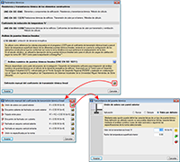
- By manually defining its properties
These are defined using the ![]() button (Manual definition of the linear thermal transmittance coefficient) in the “Thermal parameters” dialogue box. Upon selecting the option, a dialogue box opens where users can choose amongst three options to define the linear transmittance of each type of thermal bridge:
button (Manual definition of the linear thermal transmittance coefficient) in the “Thermal parameters” dialogue box. Upon selecting the option, a dialogue box opens where users can choose amongst three options to define the linear transmittance of each type of thermal bridge:
- Never
The thermal properties of the selected linear thermal bridge are not considered.
- Always
Always consider the thermal properties defined for the selected thermal bridge.
- Default value
The thermal properties defined for the selected linear thermal bridge will be used in the analysis if it has not been possible to establish them using the numerical analysis (if activated) or following the specifications of the reference code used.
- Using the Numerical analysis of linear thermal bridges module
Once the construction elements have been introduced in CYPECAD MEP, the program automatically identifies the thermal bridges of the thermal envelope of the building when the analysis is launched (Results > Analyse). The Numerical analysis of linear thermal bridges module calculates the thermal bridges it detects if the Numerical analysis of linear thermal bridges option has been activated in the General data dialogue box (Job > General data).
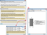
- By introducing a Floor slab thermal break
Floor slab thermal breaks can be introduced in the floor slabs (Construction elements > Floor slab thermal break or using the ![]() button). This way, the continuity of the insulation is assured at the thermal bridges of the slab and the energy consumption of the building is limited. Users introduce a thermal break, on plan, at the edge of the slab (where a thermal bridge is present), indicating the initial and final points of the break and its linear transmittance. The program detects the break and substitutes the transmittance of the thermal bridge with the transmittance defined in the break.
button). This way, the continuity of the insulation is assured at the thermal bridges of the slab and the energy consumption of the building is limited. Users introduce a thermal break, on plan, at the edge of the slab (where a thermal bridge is present), indicating the initial and final points of the break and its linear transmittance. The program detects the break and substitutes the transmittance of the thermal bridge with the transmittance defined in the break.
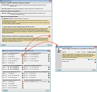
Within the Thermal parameters dialogue box, users can define different analysis methods or assign values for the thermal parameters for a type of linear thermal bridge. To avoid duplicating, the program follows a priority order to assign the thermal parameters when calculating the heat transmission via a thermal bridge:
- Presence of thermal breaks
If the user has defined thermal breaks, its thermal parameters are used to calculate the transmission via the thermal bridge where it has been defined.
- Manually introduced value using the “Always” or “Never” option
These values can be defined for each type of thermal bridge in the “Thermal parameters” dialogue box (Thermal parameters > Manual definition of the linear thermal transmittance coefficient > ![]() button >
button > ![]() button of a specific type of thermal bridge > select “Always” or “Never” > introduction of the thermal parameters).
button of a specific type of thermal bridge > select “Always” or “Never” > introduction of the thermal parameters).
- Value calculated using the numerical analysis of linear thermal bridges
If this module has been activated, the analysis will be for the set of thermal bridges it analyses.
- Value obtained using the reference code
The reference code depends on the country that is selected when a new job is created.
- Manually introduced value using the “Default value” option
These values can be defined for each type of thermal bridge in the “Thermal parameters” dialogue box (Thermal parameters > Manual definition of the linear thermal transmittance coefficient > ![]() button >
button > ![]() button of a specific type of thermal bridge > select “Default value” > introduction of the thermal parameters).
button of a specific type of thermal bridge > select “Default value” > introduction of the thermal parameters).
 EN ISO 14683. New thermal insulation code in the international version of CYPECAD MEP
The EN ISO 14683 insulation code (Thermal bridges in building construction. Linear thermal transmittance. Simplified methods and default values) has been implemented in the Air conditioning tab of the international version of CYPECAD MEP.
 Descriptive report of linear thermal bridges
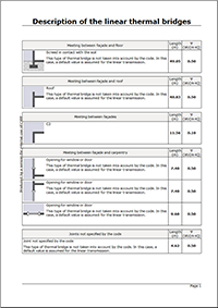
A new report has been implemented in which the properties and results of the thermal bridges that have been analysed are generated automatically.
This report can be obtained from the Air conditioning tab; for all the edges detected in the job (File > Print > Job reports > Description of the linear thermal bridges); or for the edges of a precinct (Results > Thermal bridge view > select a precinct > select the Thermal bridges tab in the dialogue that appears on screen).
New features in Arquimedes and Job Control
 New columns with partial payments in the Decomposition tree window
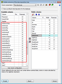
New columns have been implemented in the Decomposition tree window to display partial payments at chapter, job unit or auxiliary price level. Users can activate these columns, and include them in customised column presentations, by accessing the Visible columns of the decomposition tree dialogue box (double click with the left mouse button on any part of the Decomposition tree window header).
The information displayed in these new columns is the same as that displayed on the bottom part of the screen when a cell of the Amount column, that belongs to a chapter, job unit or auxiliary price, is selected.
Customised column names in the Decomposition tree window
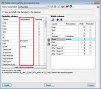
Users can now provide a customised name to the columns in the “Decomposition tree” window, by accessing the Visible columns of the decomposition tree dialogue box (double click with the left mouse button on any part of the Decomposition tree window header). The customised name must be indicated in the Personalised column in the Available columns section within the dialogue box.
The columns, located in the top part of the Decomposition tree window, which have been assigned a customised name, are displayed with a small red triangle in the bottom right hand corner of the cell in which the customised name appears.
The customised names of the columns are stored as user data, and therefore, are saved in the computer in which the names have been introduced and not together with the job that is under edition.
Reading of the user license key file (clv)
The user license keys are CLV files, which CYPE occasionally sends to users so their user license can access all the modules and programs that have been purchased (users are not required to have these files).
Up to now, if a CYPE user were to receive a CLV file, it had to be placed in the root directory of the “C:/” hard drive or in the “CYPE Ingenieros” directory of the hard drive in which CYPE has been installed.
As of the 2013.j version, users can indicate where the user license key CLV file is going to be copied to. To do so, a button: Reading of the license key file, has been implemented in the Permissions dialogue box (select the License xxxxx option, located in the bottom right hand corner of the CYPE main program menu). Upon selecting this option, a dialogue box of the operating system of the computer will open, where users can select the directory to which the CLV license key file is to be copied.
If no CYPE programs have been installed, they should first be installed and then indicate the location of the license key file, if it has been sent to the user. A user license is not required to install CYPE programs, neither must the user license keys be installed beforehand. The user license and keys, are only required to operate the program, although there are CYPE program versions that do not require a user license.
Return to the 2013 version download area
Tel. USA (+1) 202 569 8902 // UK (+44) 20 3608 1448 // Spain (+34) 965 922 550 - Fax (+34) 965 124 950