
New features and download of the 2013.h version
(21st December 2012)
![]()
Improvements in code application
Concrete structures
NTC: 14-01-2008 (Italy)
Norme tecniche per le construzioni.
The NTC: 14-01-2008 Italian code has been implemented in Punching shear verification. This code was already implemented as of previous versions in other CYPE programs (CYPECAD, Metal 3D, Continuous beams, Box Culverts and Foundation elements).
Loads on structures. Seismic loads
Capacity design criteria for seismic design of concrete columns and beams
Information on the implementation of Seismic capacity design criteria for concrete columns and beams can be found in the new features of CYPECAD on this webpage.
REP - 04 (Panama). Static analysis and correction due to base shear
Reglamento para el Diseño Estructural en la República de Panamá (REP-04).
This code was already implemented as of previous versions for CYPECAD and Metal 3D for the dynamic analysis method (spectral modal).
The 2013.h version includes in CYPECAD:
- A static analysis method (equivalent lateral force)
The analysis method selection (dynamic or static) is carried out using the Analysis method option within the dialogue box where the seismic load is defined.
- Correction due to base shear
This correction is applied to the seismic analysis when this is done using the dynamic analysis (spectral modal). More information on this topic can be found in the Correction due to base shear section.
New features in CYPECAD
Capacity design criteria for seismic design of concrete columns and beams
The 2013.e and 2013.g versions of CYPECAD implemented the capacity design criteria for bending at the supports in accordance with Annex 10 of the EHE-08 code and in accordance with the NCSE-02 code, and the capacity design criteria for shear for the seismic design of beams in accordance with the same codes.
Now, for the 2013.h, the following codes have been implemented:
- The capacity design criteria for shear at concrete supports in accordance with Annex 10 of the EHE-08 code (Spain).
- The capacity design criteria for shear at concrete supports and beams in accordance with the IS 13920: 1993 (Indian).
The capacity design criteria which are currently implemented are:
- For concrete supports:
- Capacity design criteria for bending and shear in accordance with Annex 10 of the EHE-08 code (Spain).
- Capacity design criteria for bending in accordance with NCSE-02 (Spain)
- Capacity design criteria for shear in accordance with IS 13920: 1993 (India)
- For concrete beams:
- Capacity design criteria for shear in accordance with Annex 10 of the EHE-08 code (Spain).
- Capacity design criteria for shear in accordance with NCSE-02 (Spain)
- Capacity design criteria for shear in accordance with IS 13920: 1993 (India)
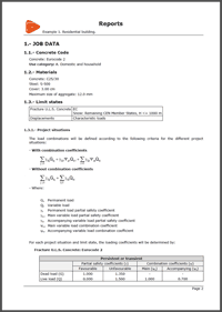
These design criteria are applied in CYPECAD and are specified in the Detailed Ultimate Limit State check reports if the selected codes are those which have been indicated.
Beam editor of CYPECAD
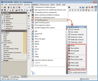
The following improvements have been implemented in the beam detailing representation:
- Marks at bar ends
 The program marks (using inclined lines) bars which are anchored without any bends. These marks are visible within the on-screen display of the longitudinal section of the frame and on reinforcement details drawings. These marks are only provided if the ends of the bars are drawn overlapping other bars, due to them being in the same horizontal plane.
This way, users can distinguish where the bar begins and ends within the longitudinal section of the frame, even if one end overlaps another bar placed in the same horizontal plane (within the longitudinal section).
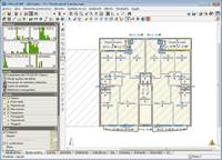
- Representation of the reinforcement details in frame drawings
Two options have been implemented, which are used to represent the reinforcement details in two ways within the frame drawings:
 Details of reinforcement outside of the frame
The reinforcement details are drawn outside the longitudinal section of each frame. This method has been used to represent the details as of previous versions.
- Reinforcement details only in the table
The reinforcement details are not drawn in the frame and are only defined in the Reinforcement details table.
New features in Punching shear verification
Implementation of NTC: 14-01-2008 (Italy)
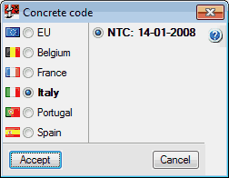 The NTC: 14-01-2008 Italian code (Norme tecniche per le construzioni) has been implemented in the program. This code was already implemented as of previous versions in other CYPE programs (CYPECAD, Metal 3D, Continuous beams, Box Culverts and Foundation elements).
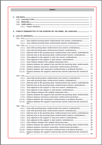
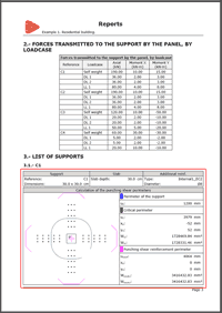
Improvements in Design check reports
The following improvements have been included in the check reports generated by the program:
- Index of the report
- Properties table of the support, checked sections and reinforcement
New features in Continuous beams
Continuous beams now includes the following improvements:
- Marks to differentiate between longitudinal bars placed in the same horizontal plane
- Configuration of the reinforcement details drawing
These improvements are the same as those which have been implemented the Beam editor of CYPECAD.
New features in CYPECAD MEP
Export to IFC
 The following Air handling system elements (Air conditioning > Installation > Air handling systems) could already be exported to IFC format (Industry Foundation Classes) as of previous versions, in accordance with the standards of the format. Now, in the 2013.h version, the export includes more properties of these elements and improvements in some of those which were exported (materials, layer, colour, geometry, analysis data...):
- Diffuser
- Plenum diffuser
- Discharge grille
- Nozzle
- Return air grille
- Plenum return air grille
- Intake air grille
- Linear centrifugal ventilator
Acoustic analysis
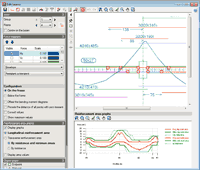
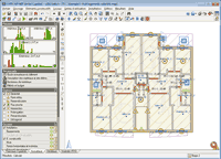
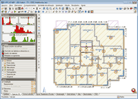
On-screen statistical representation of the acoustic insulation of the building
As of the 2013.h versions, the side menu of the screen includes graphs of the acoustic insulation for each type of noise.
These graphs originally appeared in the Acoustic analysis report of the building (File > Print > Job report). They offer a statistical representation of the results of the acoustic insulation of the building.
Five graphs are generated, one for each type of noise (Internal airborne noise using vertical separation elements. Airborne noise using horizontal separation elements. Impact noise. External airborne noise and Airborne noise in partitions).
Each graph contains vertical bars displaying the acoustic insulation value of the emitter and receptor precinct pairs, in which the receptor is a precinct protected against the represented noise. The height of the vertical bar depends on the number of precinct pairs which have the same design acoustic insulation value. The colour of each bar can be green up to a specific height and then red. The height of the green area indicates the number of pairs which meet the acoustic insulation requirements and, conversely the red area represents those that do not.
By observing these graphs, users can see if the acoustic insulation requirements of the building are met at a glance (depending on the colour that predominates) without having to check the errors on a floor-by-floor basis.
New features in Arquimedes and Job Control
Export a bill of quantities to FIEBDC-3 as a blind bill of quantities
A new option has been included when exporting to FIEBDC-3 format (File > Export > Export to FIEBDC-3). This new option exports the bill of quantities as a Blind bill of quantities (only quantities). Once this option has been activated, another can be activated which allows to Include the complete decomposition of the job items.
Tel. USA (+1) 202 569 8902 // UK (+44) 20 3608 1448 // Spain (+34) 965 922 550 - Fax (+34) 965 124 950