
New features and download of the 2013.g version
(5th December 2012)
![]()
Improvements in code application
Loads on structures. Seismic loads
Capacity design criteria for seismic design of concrete columns and beams
Information on the implementation of Seismic capacity design criteria for concrete columns and beams can be found in the new features of CYPECAD on this webpage.
CHOC-04 (Honduras), COVENIN 1756-1:2001 (Venezuela) and NSE-10 (Guatemala)
Improvements have been implemented in the following seismic codes:
- CHOC-04 (Honduras)
Código Hondureño de la Construcción. Normas Técnicas Complementarias. XII.
Cargas y Fuerzas Estructurales. Diseño por Sismo.
- COVENIN 1756-1:2001 (Venezuela)
Norma Venezolana COVENIN 1756-1:2001. Edificaciones sismorresistentes.
- NSE-10 (Guatemala)
Normas de Seguridad Estructural de Edificaciones y Obras de Infraestructura para la República de Guatemala, edición 2010.
These codes were already implemented in CYPECAD and Metal 3D as of previous versions. They are used in CYPECAD together with the ACI 318M-08 (USA - International) concrete code.
As of the 2013.g version, the analysis in CYPECAD using the ACI 318M-08 (USA - International) concrete code in combination with seismic codes: CHOC-04 (Honduras), COVENIN 1756-1:2001 (Venezuela) and NSE-10 (Guatemala), offers:
- Detailed ultimate limit state check reports for concrete columns in CYPECAD's column editor.
- Advanced edition of the columns in CYPECAD.
- Automatic generation of the column reinforcement tables.
CYPECAD's new column editor offers and extensive and meticulous information on the data, checks and results of all the concrete and steel columns of the job including their detailed Ultimate Limit State (U.L.S.) check reports. The U.L.S. reports allow users to verify, justify and optimise the design of the columns in CYPECAD.
More information on the concrete column editor of CYPECAD can be found on the following links:
- CYPE programs which generate U.L.S. check reports
- Detailed ultimate limit state check reports for concrete columns in CYPECAD's new column editor
- Automatic generation of column reinforcement tables
COVENIN 1756-1:2001 (Venezuela). Static analysis and correction due to base shear
Norma Venezolana COVENIN 1756-1:2001. Edificaciones sismorresistentes.
This code was already implemented as of previous versions for CYPECAD and Metal 3D for the dynamic analysis method (spectral modal).
The 2013.g version includes in CYPECAD:
- A static analysis method (equivalent lateral force)
The analysis method selection (dynamic or static) is carried out using the Analysis method option within the dialogue box where the seismic load is defined.
- Correction due to base shear
This correction is applied to the seismic analysis when this is done using the dynamic analysis (spectral modal). More information on this topic can be found in the Correction due to base shear section.
New features in CYPECAD
Capacity design criteria for seismic design of concrete columns and beams
The 2013.e version of CYPECAD implemented "the capacity design criteria for bending at the supports in accordance with Annex 10 of the EHE-08 code". Now, for the 2013.g version, other capacity design criteria will be implemented for seismic design, with which CYPECAD designs concrete beams and columns. The capacity design criteria implemented up to now are:
- The capacity design criteria for bending at the supports in accordance with Annex 10 of the EHE-08 code (Spain) - as of the 2013.e version.
- The capacity design criteria for bending at the supports in accordance with the NCSE-02 seismic code (Spain) - as of the 2013.g version.
- The capacity design criteria for shear in beams in accordance with Annex 10 of the EHE-08 code (Spain) - as of the 2013.g version.
- The capacity design criteria for shear in beams in accordance with the NCSE-02 seismic code (Spain) - as of the 2013.g version.
These design criteria are applied in CYPECAD and are specified in the Detailed Ultimate Limit State check reports if the selected codes are those which have been indicated.
Beam editor of CYPECAD
CYPECAD's new beam editor (implemented in the 2013.e version) includes the following new features for the 2013.g version:
- Redesign frame reinforcement
- Block reinforcement
- Join assembly or skin reinforcement
- Conservation of the lateral menu configuration
 Redesign frame reinforcement
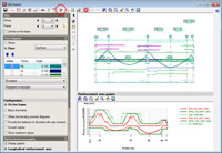
A new option: Redesign frame, represented by the ![]() button, has been implemented in the top toolbar of the beam editor. This option redesigns the frame with the forces calculated by CYPECAD, even if the option to block the reinforcement of the frame is activated in the editor (new option implemented in this version, more details of which are provided below.)
button, has been implemented in the top toolbar of the beam editor. This option redesigns the frame with the forces calculated by CYPECAD, even if the option to block the reinforcement of the frame is activated in the editor (new option implemented in this version, more details of which are provided below.)
 /
/  Block/Unblock frame reinforcement
The new Block or Unblock frame reinforcement option is represented by an icon situated in the View section of the lateral menu of the new beam editor. This icon can be represented in two ways: open padlock (![]() ) or closed padlock (
) or closed padlock (![]() ). The open padlock (
). The open padlock (![]() ) indicates the reinforcement of the frame being edited is not blocked and the closed padlock (
) indicates the reinforcement of the frame being edited is not blocked and the closed padlock (![]() ) indicates it is blocked. By clicking on the icon, the blocked status of the beam reinforcement changes. Blocking of the reinforcement is only effective for actions carried out outside the editor. In other words, if the frame's reinforcement is blocked, (
) indicates it is blocked. By clicking on the icon, the blocked status of the beam reinforcement changes. Blocking of the reinforcement is only effective for actions carried out outside the editor. In other words, if the frame's reinforcement is blocked, (![]() ) CYPECAD will not be able to modify it with any of the reinforcement options or even by analysing the job (Beam Definition tab > Analyse). Nonetheless, even if the reinforcement of the frame is blocked (
) CYPECAD will not be able to modify it with any of the reinforcement options or even by analysing the job (Beam Definition tab > Analyse). Nonetheless, even if the reinforcement of the frame is blocked (![]() ), it can be modified in the Beam editor (changing it manually or using the Redesign button
), it can be modified in the Beam editor (changing it manually or using the Redesign button ![]() implemented in this version).
implemented in this version).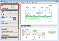
Join assembly or skin reinforcement
A new option was implemented in the 2013.e version: Join longitudinal reinforcement (included in the Longitudinal reinforcement dialogue box which is activated using the ![]() button from the toolbar of the beam editor), for CYPECAD's beam editor and for Continuous beams. Since then, this option allows for additional reinforcement bar packs of the same diameter to be joined.
button from the toolbar of the beam editor), for CYPECAD's beam editor and for Continuous beams. Since then, this option allows for additional reinforcement bar packs of the same diameter to be joined.
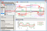 Now, in the 2013.g version, the Join reinforcement option allows for assembly and skin reinforcement in adjacent spans to be joined. Using this option, users can also select the assembly or skin reinforcement of a span and then that of the adjacent span. The program will join the selected assembly or skin reinforcement, by copying the reinforcement which is first selected to that which is selected in second place. Unlike the joining of additional reinforcement (for which the program only allows for reinforcement of the same diameter to be joined without substituting the reinforcement of one span for the other), joining of the assembly or skin reinforcement implies that the reinforcement selected in second place will be substituted by those that were selected first (regardless of the number of bars and diameter).
Maintenance of the lateral menu configuration
The configuration options of the beam editor are saved automatically for the next time users edit the reinforcement of a frame. These options are the same for CYPECAD's beam editor and Continuous beams.
New features in Punching shear verification
Representation in the drawings of the plan view of the punching shear reinforcement
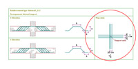
The drawings generated by the Punching shear verification program include a plan view of the punching shear reinforcement that has been provided.
Implementation of examples designed in accordance with Eurocode 2
The 2013.g version of Punching shear verification includes examples designed in accordance with Eurocode 2.
New features in Continuous beams
Continuous beams now includes the following new features:
- Re-design frame reinforcement
- Join assembly or skin reinforcement
- Conservation of the lateral menu configuration
These improvements are the same as those which have been implemented in the CYPECAD's beam editor (except the option to Block reinforcement, which, given how it operates, is not applicable to this program).
Arquimedes
Connection with Allplan 13 (32-bit)
Arquimedes has been updated so to include changes introduced in Allplan 13 (32-bit) and maintain the connection between both applications.
Tel. USA (+1) 202 569 8902 // UK (+44) 20 3608 1448 // Spain (+34) 965 922 550 - Fax (+34) 965 124 950