NEW MODULES
NEW FEATURES OF EXISTING PROGRAMS
- General improvements
- New features common to several programs
- CYPE Architecture
- Exporting surface area tables to the BIM project for Open BIM Layout
- Improved intersection solutions
- Improved colours and textures in the "Architecture" tab
- Detecting duplicated elements in the sketch entry mode
- Improved operation of the "Divide wall or floor slab" and "Edit geometry" tools in plan views
- Improved lift introduction
- Open BIM Site
- CYPECAD
- Open BIM Layout / StruBIM Steel / CYPE Connect
- New scene drawing modes: "Vector image" and "Hybrid image"
- Drawing hidden lines
- Continuous dimensioning
- Angle dimensioning
- Section depth editing
- Text-only tag
- Line type editing for vector image scenes
- Print management by categories of elements
- Management of categories that can be snapped from the sidebar
- Keyboard shortcuts to commonly used tools
- Editing the line style for the outline of section fills in scene views
- Grid editing by scene view
- Sheet style
- Pinned menu bars
- Regenerating scene views
- StruBIM Steel / CYPE Connect
- StruBIM Steel
- Structural steel detailing drawings (new module)
- Improvements in the "Copy" tool
- Managing tags from the sidebar
- Managing visibility and snapping by elements from the sidebar
- Rearranged option bar
- Numbering options
- Tools for numbering a selection of elements
- Selecting the main part of the assembly
- Automatic grouping of assemblies according to the place of execution of welds, bolts and anchors
- Analysing multiple connections
- Options for grouping and generating nodes
- Editing the connection reference
- New report types
- New menu option for exporting to DSTV and STEP formats
- Model update during editing
- StruBIM REBAR
- CYPEFIRE
- CYPEFIRE / CYPELUX
- CYPETHERM LOADS
- Open BIM Quantities / Applications with a "Bill of quantities" tab
- Applications with a "Bill of quantities" tab
NEW MODULES
Structural steel detailing drawings (new StruBIM Steel module)
In version 2023.d, StruBIM Steel includes the new “Structural steel detailing drawings” module. This module allows the program to generate graphical documents of the structure. Using these tools, users will be able to create sheets of the parts (sections and plates), assembly sheets, joint sheets and sheets with the general model views. The “Generation options”, “Parts”, “Assemblies”, “Joints”, “Model views”, “Composition” and “List” tools can be accessed from the “Sheets” menu.
In order to work with this module, the user’s license must have the corresponding permission.
More information on the features of this StruBIM Steel module is available at Structural steel detailing drawings.
NEW FEATURES OF EXISTING PROGRAMS
General improvements
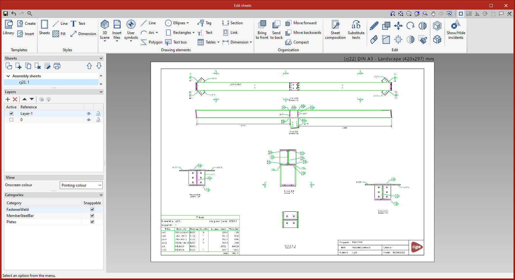
Font size
The “Font size” option has been added to the general configuration menu of the applications. This tool allows users to increase or decrease the basic size of the font used in the user interface of the programs. Thanks to this implementation, the accessibility of the applications has been improved while also ensuring the correct visibility of the content on devices with different screen resolutions.
To enter a “Basic size” the “Set custom font size” option must be checked. The size users can enter is the application’s basic font size. Any other font sizes that may exist in the program’s interface will be automatically modified proportionally according to the change in the basic size.
It is important to note that, as this is a common parameter, its modification will affect all installed CYPE tools.
New features common to several programs
Programs included in the Open BIM workflowGraphical editing of the reference system of the model |
|
|
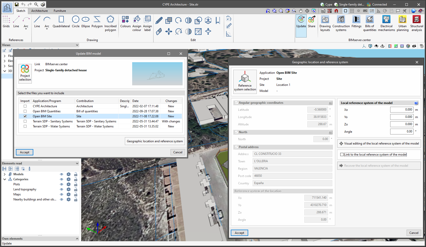
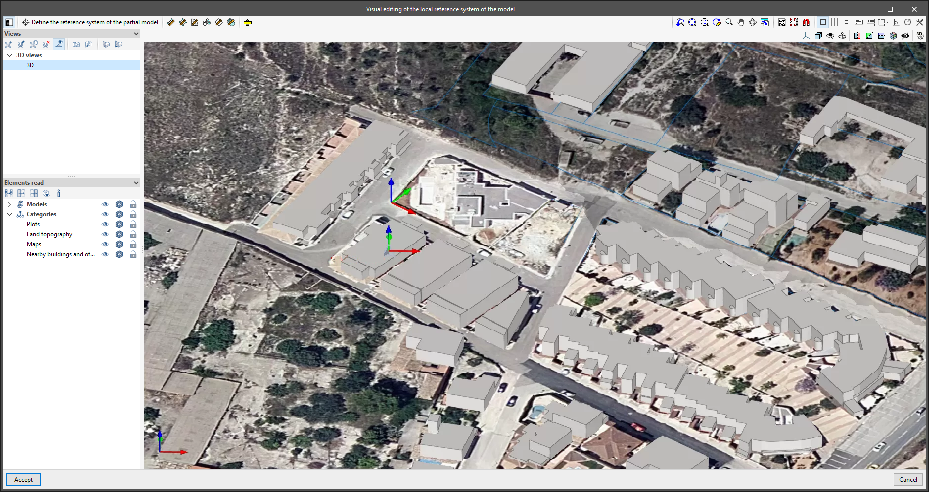
Since version 2022.a, the applications integrated within the Open BIM workflow via the BIMserver.center platform include a tool for managing project reference systems. This option is available from the configuration window that appears when linking or updating a BIMserver.center project via the “Geographic location and reference system” option. As of version 2023.d, the applications now allow users to run a graphical environment where they can visually define a reference system for their model. To do this, the “Geographic location and reference system” window now contains the “Visual editing of the local reference system of the model” option. From the “Visual editing of the local reference system of the model” window, the origin and orientation of the reference system of the model can be indicated in the workspace with the “Define the reference system of the partial model” tool. Both the axes of the reference system of the model, which we have just entered and the axes of the reference system of the site can be viewed in the workspace. The latter appears with a “Site” tag. |
|
|
To make it easier to define the reference system, the 3D models corresponding to the BIMserver.center project contributions selected during the linking process are displayed. The management of the visibility and object snaps of these models is carried out from the “Elements read” menu in the left sidebar of the window. The “Views” menu can also be found in the same options bar, from which different types of 2D and 3D views of the model can be generated. These tools can already be found in several CYPE applications. For more information on how they work, please refer to the User’s Manual for the 3D work environment tools available in CYPE applications. |
|
Apart from 3D models, 2D drawings or plans can also be imported from CAD files (“.dxf”, “.dwg”, “.dwf”) or images (“.jpeg”, “.jpg”, “.bmp”, “.png”, “.wmf”, “.emf”, “.pcx”). These files and object snaps are managed through the “DXF-DWG Template” and “Template object snaps” options accordingly.
Once the editing is complete, the coordinates and orientation of the reference system of the model with respect to the reference system of the site are moved to the corresponding fields in the “Geographic location and reference system” window.
CYPE Architecture
Exporting surface area tables to the BIM project for Open BIM Layout
CYPE Architecture generates and exports different surface area tables. Surface area tables are generated from the floor areas of the spaces defined in the model. The surface area tables that are exported are as follows:
- Complete surface area table with all the spaces of the job
- Surface area table for each of the existing levels in the job
- Surface area table for each of the existing groups in the job
Surface area tables are updated in Open BIM Layout when any change is made in CYPE Architecture that affects the spaces and is exported to the BIM project.
Improved intersection solutions
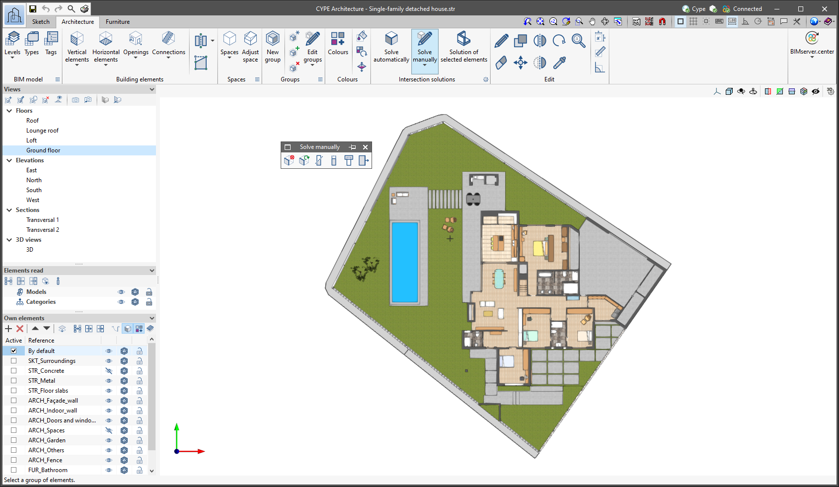
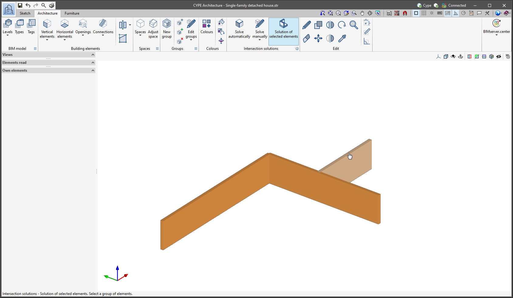
New tools and improvements have been included for intersection solutions:
|
|
|
|
|
|

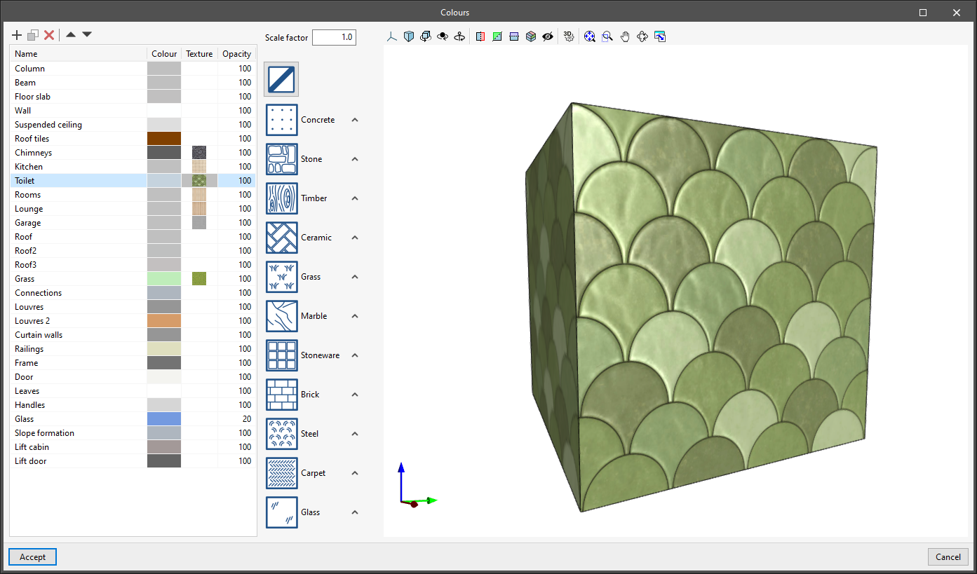
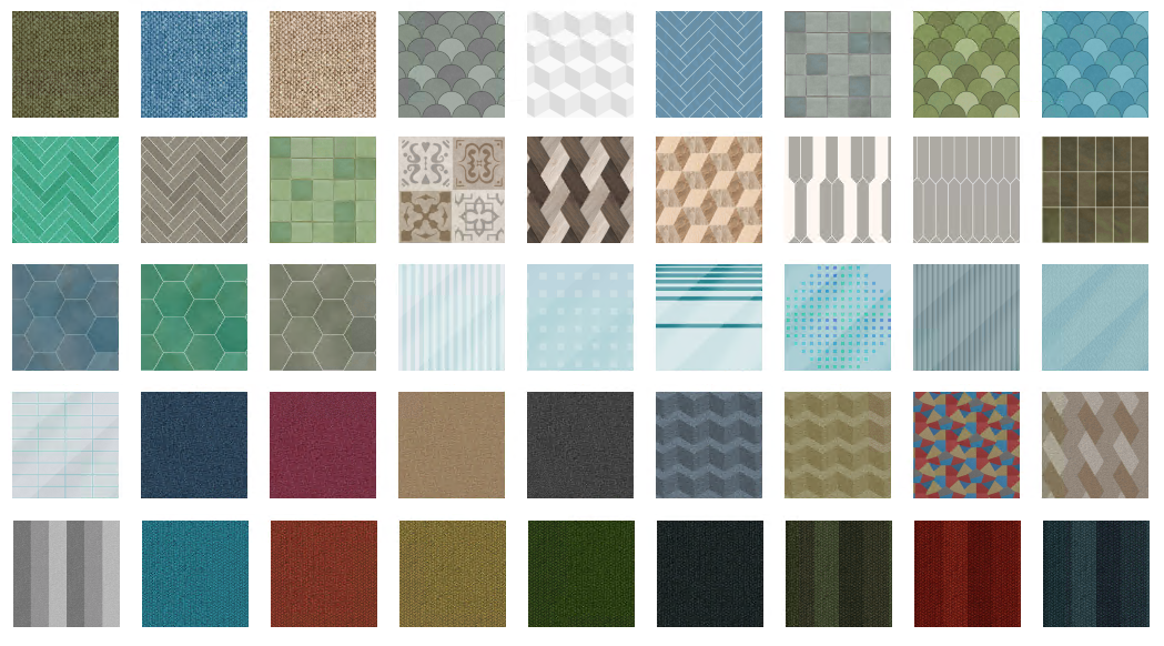
Improved colours and textures in the “Architecture” tab
|
|
|
|
Detecting duplicated elements in the sketch entry mode
When entering any element using a sketch or a sketch line, the program can detect whether the same element has already been entered in the same position.
|
If so, the colour in which the duplicate element is drawn when it is entered changes from black at the edges and green at the ends to red at all edges and ends. It also prevents users from selecting sketch elements to then transform them. |
|
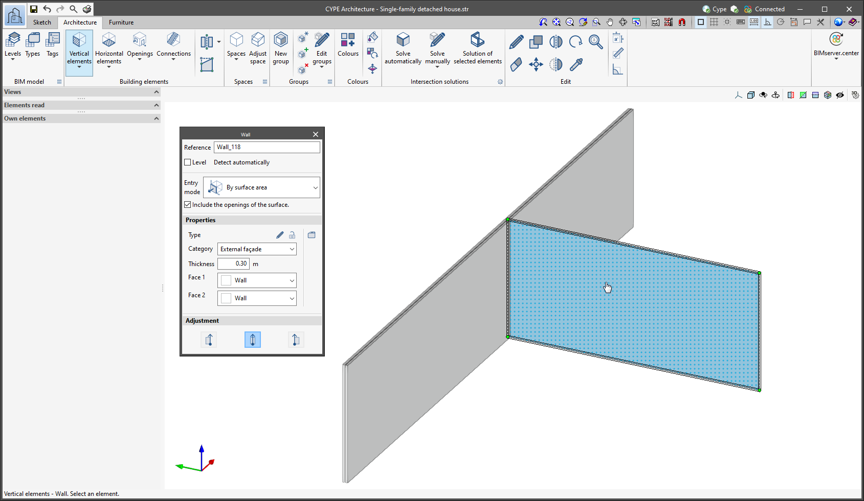
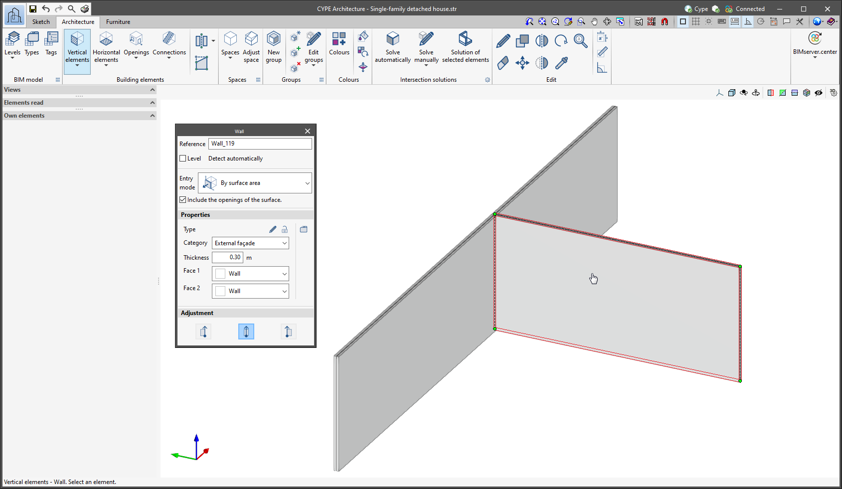
This improvement has been added to prevent users from inadvertently or mistakenly entering duplicate sketch elements.
Improved operation of the “Divide wall or floor slab” and “Edit geometry” tools in plan views
In previous versions, difficulties could arise when using the “Divide wall or floor slab” and “Edit geometry” tools in plan views (“Building elements” section in the “Architecture” tab). This was because the tools were intended to be used in 3D. The new improvements allow these tools to be used in plan views in a simple and intuitive way.
-
Edit geometry of walls, curtain walls, louvres and railings in plan views
As of version 2023.d, the “Edit geometry” tool works differently if it is used from a plan view or from a 3D view when being applied to a wall. In plan view the tool will prioritise the movement of the edges instead of the ends, allowing users to stretch the length of the elements in an easy way.
-
Divide wall at a point
When the “Divide wall or floor slab” tool is selected, it is now split into two options: “Divide wall or floor slab” and “Divide wall at a point”. With “Divide wall at a point”, a wall can be divided by a single point in plan views (but also in other types of views), which makes the program easier to use.
Improved lift introduction
As of version 2023.d, when a lift is entered in the model (available in the “Connections” tool of the “Building elements” group in the “Architecture” tab), the program detects the floor slabs it crosses and will add an opening in them automatically. It also detects any walls next to the lift door and, in that case, it also adds an opening to them automatically.
It should be noted that, if the lift is deleted, the lift openings that have been created will remain in the model and must be manually deleted if they are no longer needed in the model.
Open BIM Site
Snapping the reference system of the site |
|
|
As of version 2023.d of Open BIM Site, object snaps can be used on the reference system origin of the site. To activate or deactivate it, the “Snap” option has been added to the “Reference system of the site” section in the “Own elements” menu found in the left-hand sidebar of the application. This improvement makes it easier to use the editing tools on the site model components. |
|
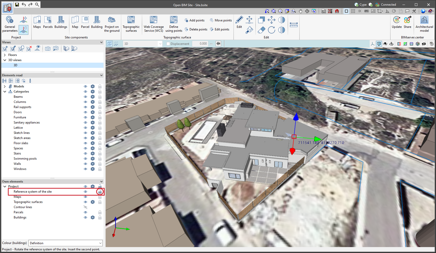
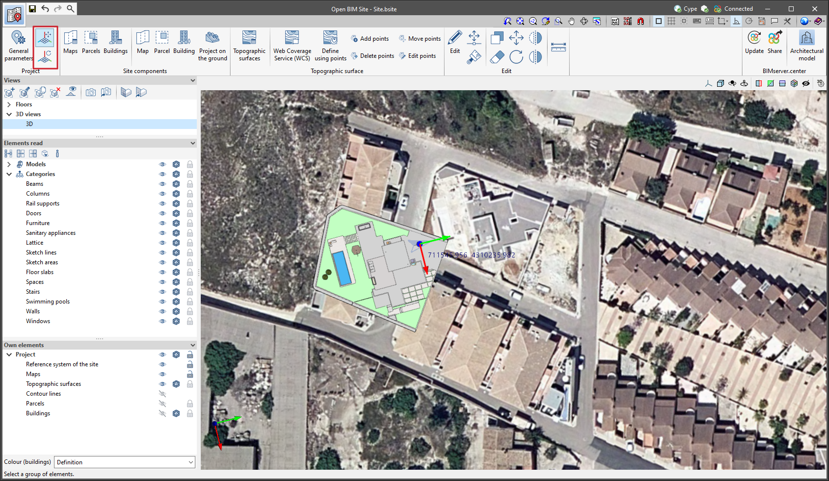
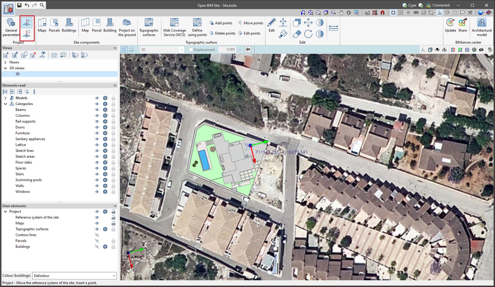
Moving and rotating the reference system origin of the site
The following options have been added to the “Project” group in the application toolbar:
-
Move the reference system of the site
Allows users to define a new position for the reference system origin of the site on the workspace. -
Rotate the reference system of the site
Allows users to specify an angle on the workspace to rotate the reference system of the site.
Thanks to these tools, the origin and orientation of the reference system of the site can now be defined graphically.
Adjusting the elements associated with the site |
|
|
The “Adjust the elements associated with the site” option has been added to the “Reference system of the site” group in the “General parameters” menu. By selecting it and editing the values of the reference system origin of the site, the elements that make up the site model (topographic surfaces, maps, parcels, etc.) will be moved to adapt to the modification. This is how the application behaved in previous versions and, consequently, it is the default value of the option. By deactivating it, the values of the reference system origin of the site can be modified, but the components of the model will not be adjusted to this modification. |
|

CYPECAD
Minor improvements and corrections
CYPECAD version 2023.d includes the following improvements and corrections of the program for certain cases:
- Envelope > Forces in beams
- An error that used to occur upon selecting “Envelope > Forces in beams” when one of the older concrete codes supported by the program was selected for the job has been fixed.
- An error that occurred upon selecting “Envelope > Forces in beams” when the combinations selected by default were not active because there were no elements of that type in the current floor, has been solved. This occurred, for example, when trying to check the envelopes or combinations in a floor in which only concrete elements had been defined when, by default, the “Laminated steel” combinations were active due to the fact that these were the last combinations checked in the last job that was opened.
- Project > General options > Limit drift between floors due to seismic action
An error that occurred when selecting “Project > General options > Limit drift between floors due to seismic action” if the job had no seismic code activated has been fixed.
- Changing column material
An error that occurred when changing the material of a circular column from steel to timber has been fixed.
- “Drift between floors due to seismic action” report
- The “Drift between floors due to seismic action” report has been improved when considering the second-order effects of seismic action.
- An error that occurred in the “Drift between floors due to seismic action” report when selecting “Interaction with the structure” in “General data > Building elements” has been fixed.
Open BIM Layout / StruBIM Steel / CYPE Connect
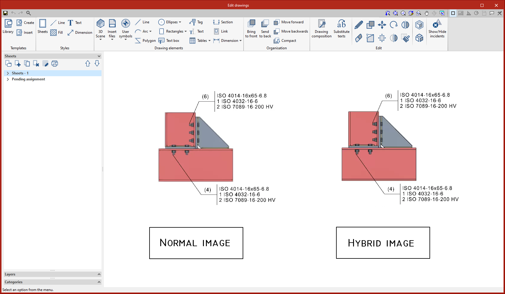
New scene drawing modes: "Vector image" and "Hybrid image"
In previous versions, the Open BIM Layout, StruBIM Steel and CYPE Connect programs had the following scene drawing modes: “Normal image” and “Monochrome image”. As of version 2023.d, two additional modes have been added:
- Hybrid image
Image with coloured elements and edge vectors. - Vector image
Image without colour fill of the elements, with vector lines.
|
|
|
|
The type of image can be selected from the editing panel in each scene. |
|
|
The following options can also be accessed from “Vectorization”:
|
|


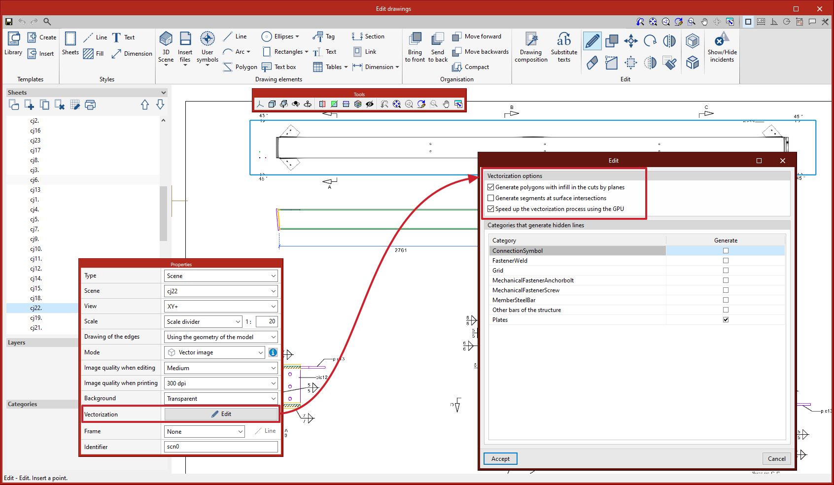
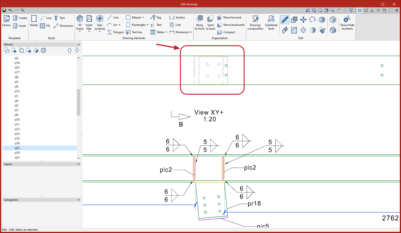
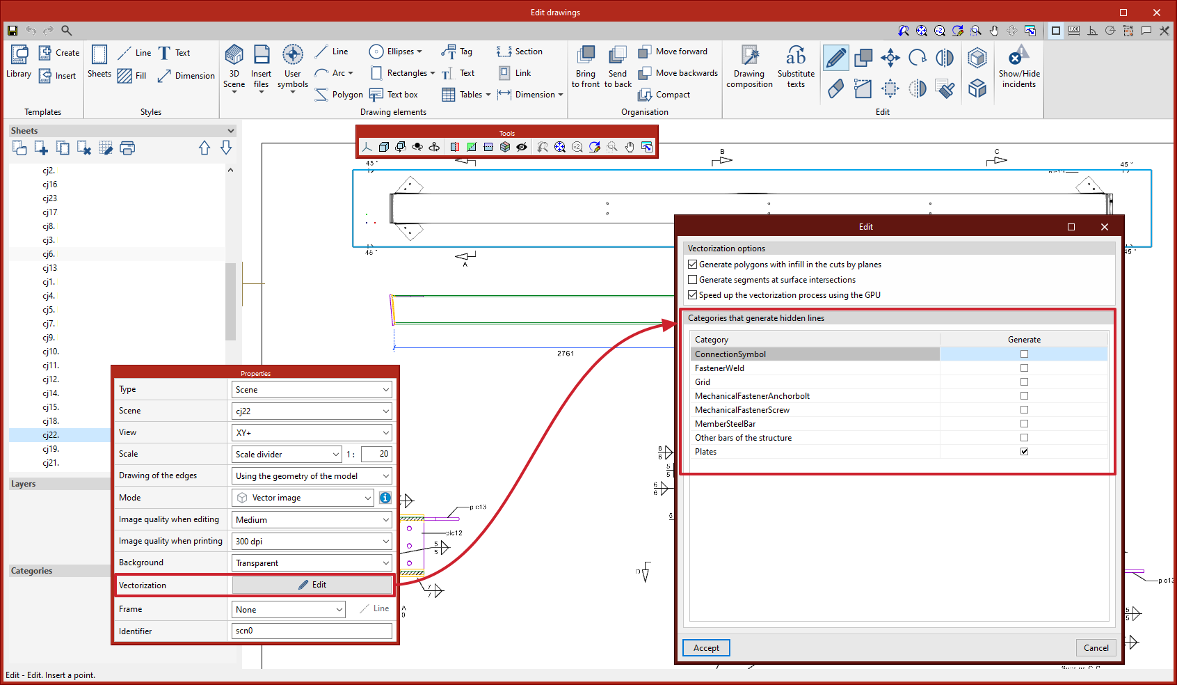
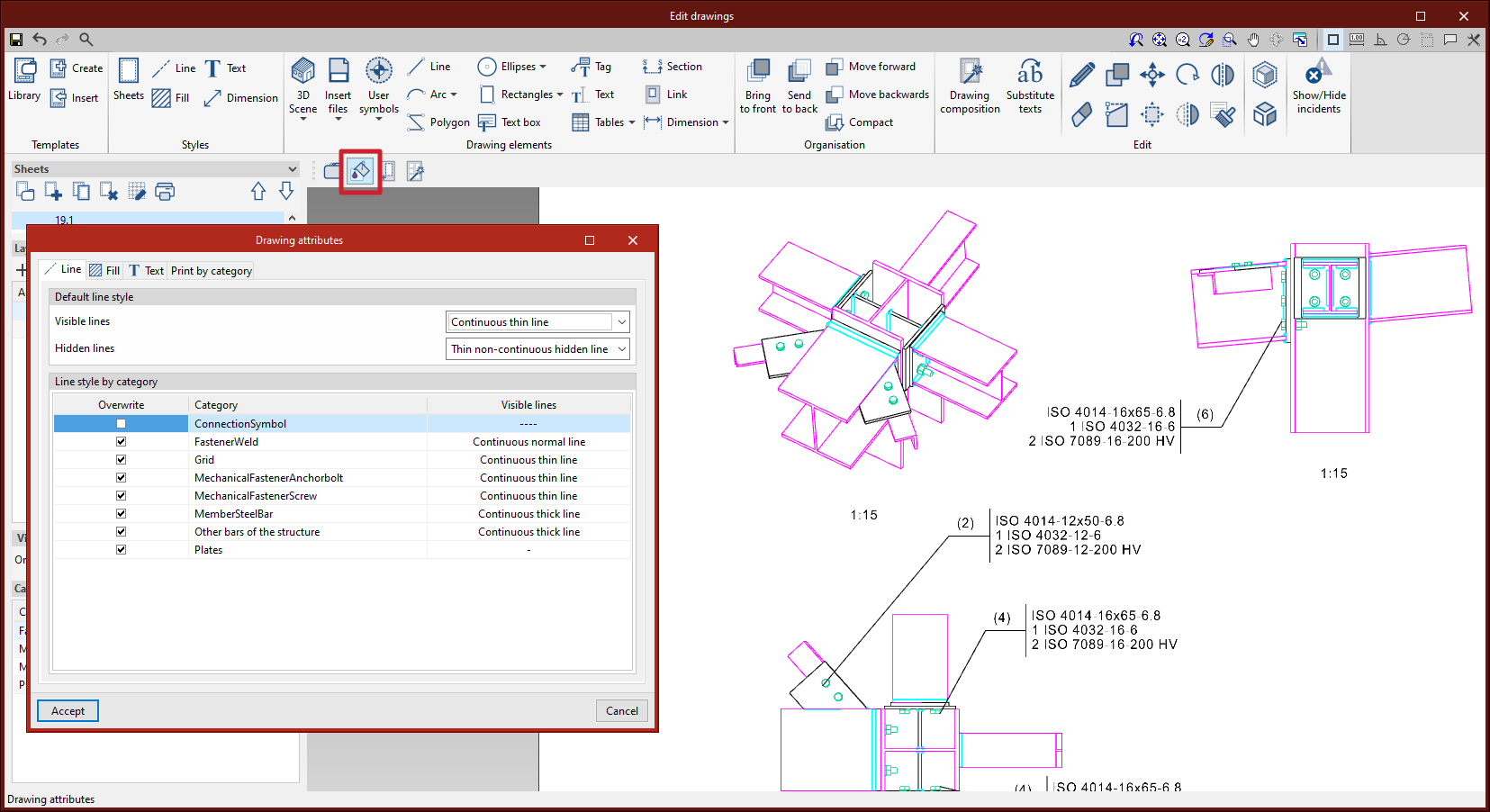
Drawing hidden lines
Hidden lines can now be drawn in scenes. Users can select the categories of elements that generate hidden lines in each scene from the editing panel of the “Vectorization” option.
|
|
|
|
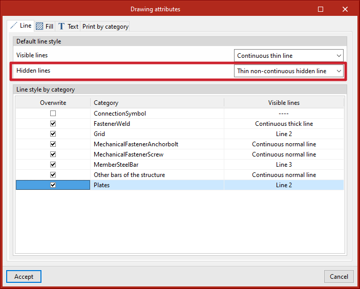
The dialogue box for editing the drawing style of the hidden lines can be accessed from the “3D Scene” tool > “Drawing attributes” option. |
|
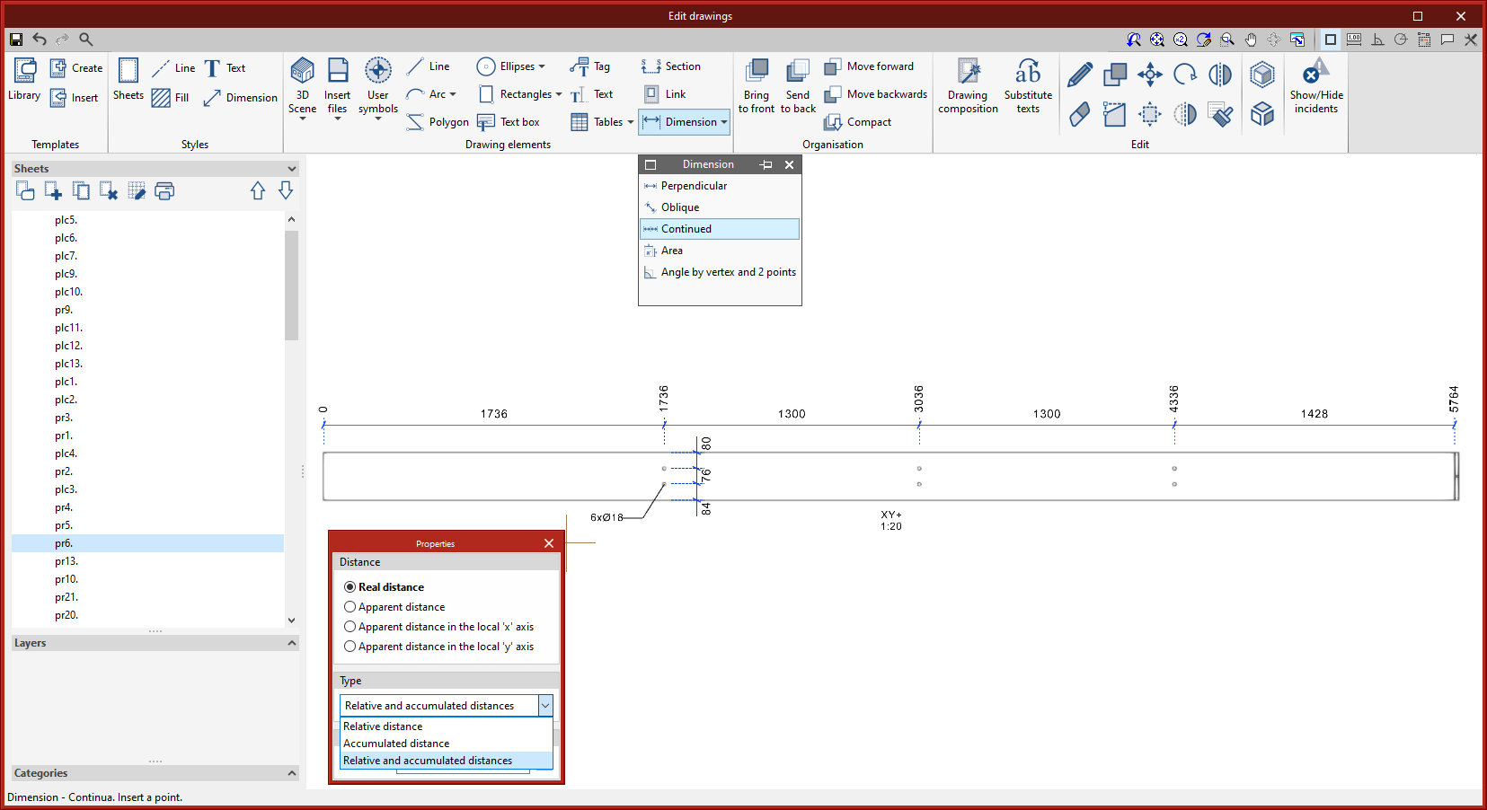
Continuous dimensioning |
|
|
A new dimensioning tool has been added. This tool allows more than one section to be continuously dimensioned. This type of dimensioning allows the “Relative distance”, the “Accumulated distance” or the “Relative and accumulated distances” to be displayed. |
|
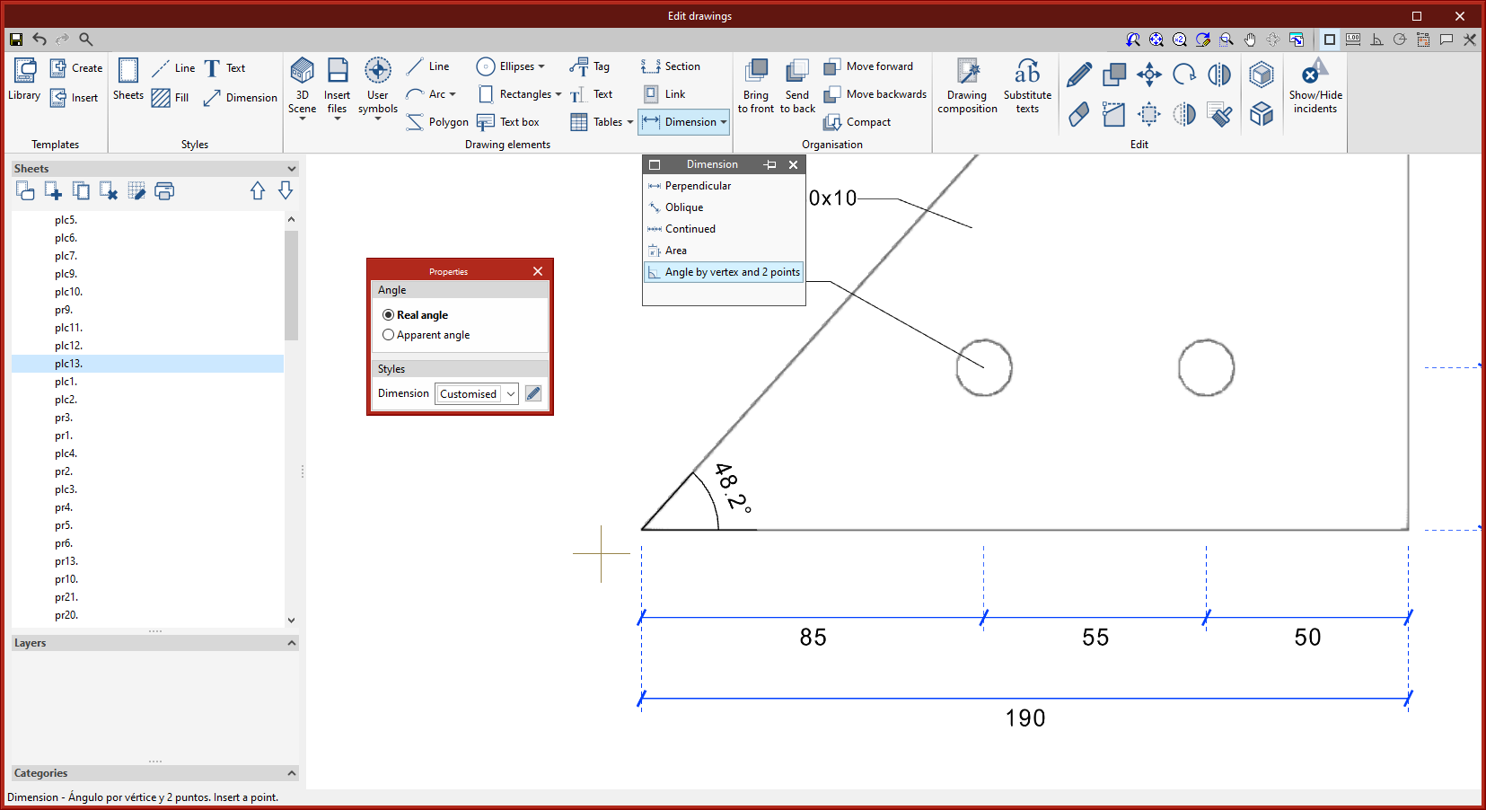
Angle dimensioning |
|
|
The dimensioning tool “Angle by vertex and 2 points” has been implemented. This tool allows angles to be dimensioned using 3 points. First, the angle’s vertex must be selected, followed by a point on each side. |
|
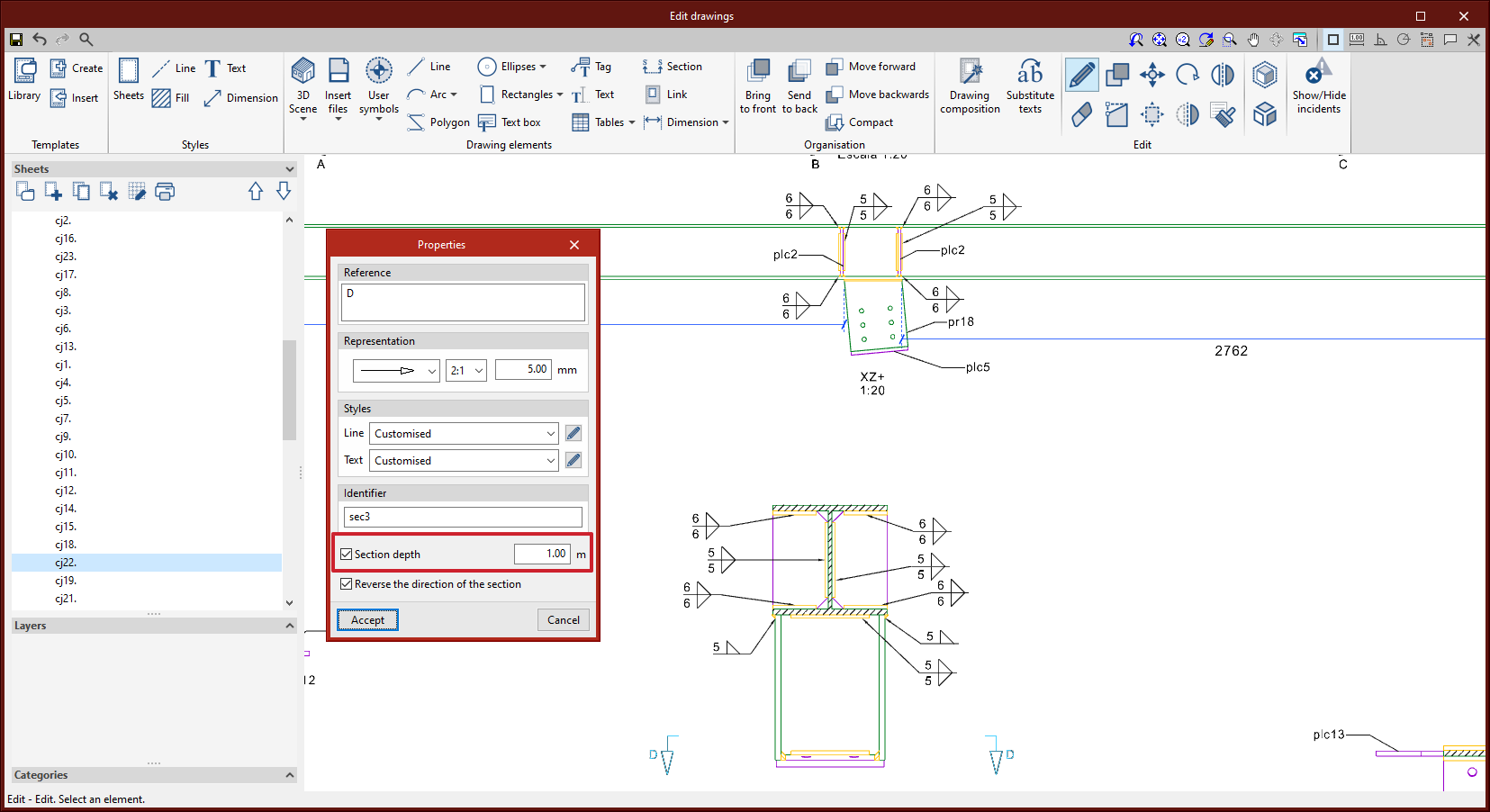
Section depth editing |
|
|
Up until version 2023.d, section depth could not be edited. Therefore, the scene was displayed from the position of the section line to the end. As of version 2023.d, the depth can be edited. This way, parts of the scene that are not relevant to the section drawing can be omitted. |
|
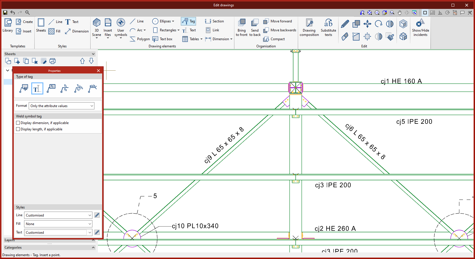
Text-only tag |
|
|
A new type of tag has been added where only text is displayed. This tag is particularly relevant to StruBIM Steel model views and assembly drawings, where the automatic tag is generated for the bars, aligned to their axis. |
|
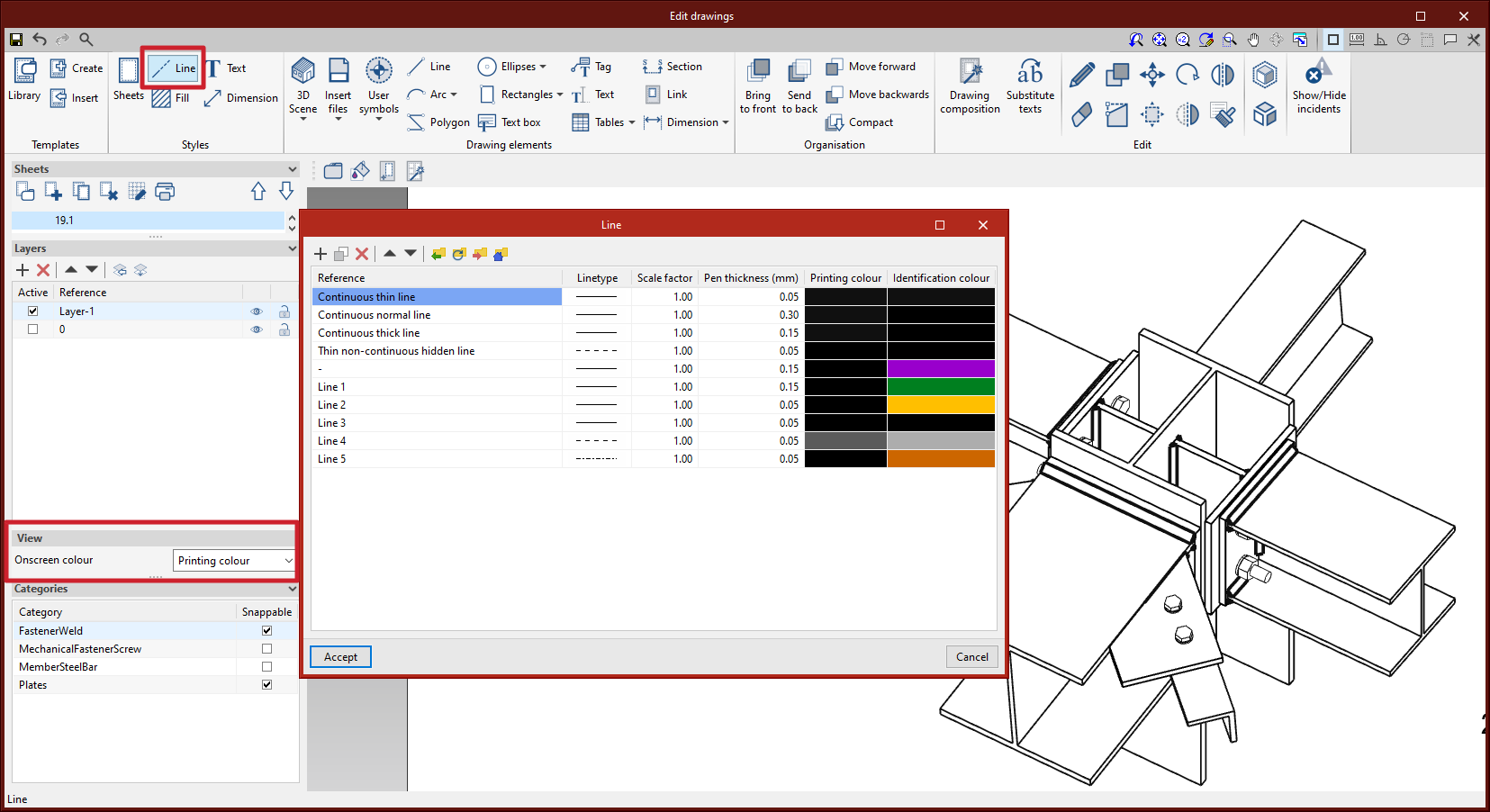
Line type editing for vector image scenes
Line style editing by category has been added. The dialogue box for editing the line style can be accessed from the “3D Scene” tool > “Drawing attributes” option. When the scenes are defined as a vector image, the edges of the elements can be seen on screen according to the line style and the colour chosen by the user between the identification colour or the printing colour.
Print management by categories of elements |
|
|
In version 2023.d, the print management of elements according to their category has been added. From “3D Scene” > “Drawing attributes”, users can access the dialogue box that allows them to select the categories to be printed (“Print by category” tab). Unchecked categories will be displayed on screen but will not be printed. This implementation is particularly relevant, for example, with connection symbols, which should be displayed on screen so they can be tagged, but not printed (see new feature “Connection symbols in drawing layouts“). |
|

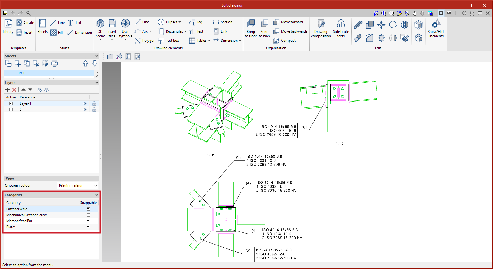
Management of categories that can be snapped from the sidebar |
|
|
In version 2023.d, the management of categories marked as “Snappable” has been added to the sidebar. Each element in the 3D scenes belongs to a category. This improvement is useful, for example, when tagging or dimensioning items to deactivate categories that don’t need to be snapped. The sidebar location allows quick access to this commonly used tool. |
|
Keyboard shortcuts to commonly used tools
The following keyboard shortcuts have been added
- Alt+G: Modify geometry
- Alt+P: Insert predefined views
- Alt+I: Perpendicular dimension
- Alt+Shift+I: Continuous dimension
- Alt+Shift+A: Angle dimension
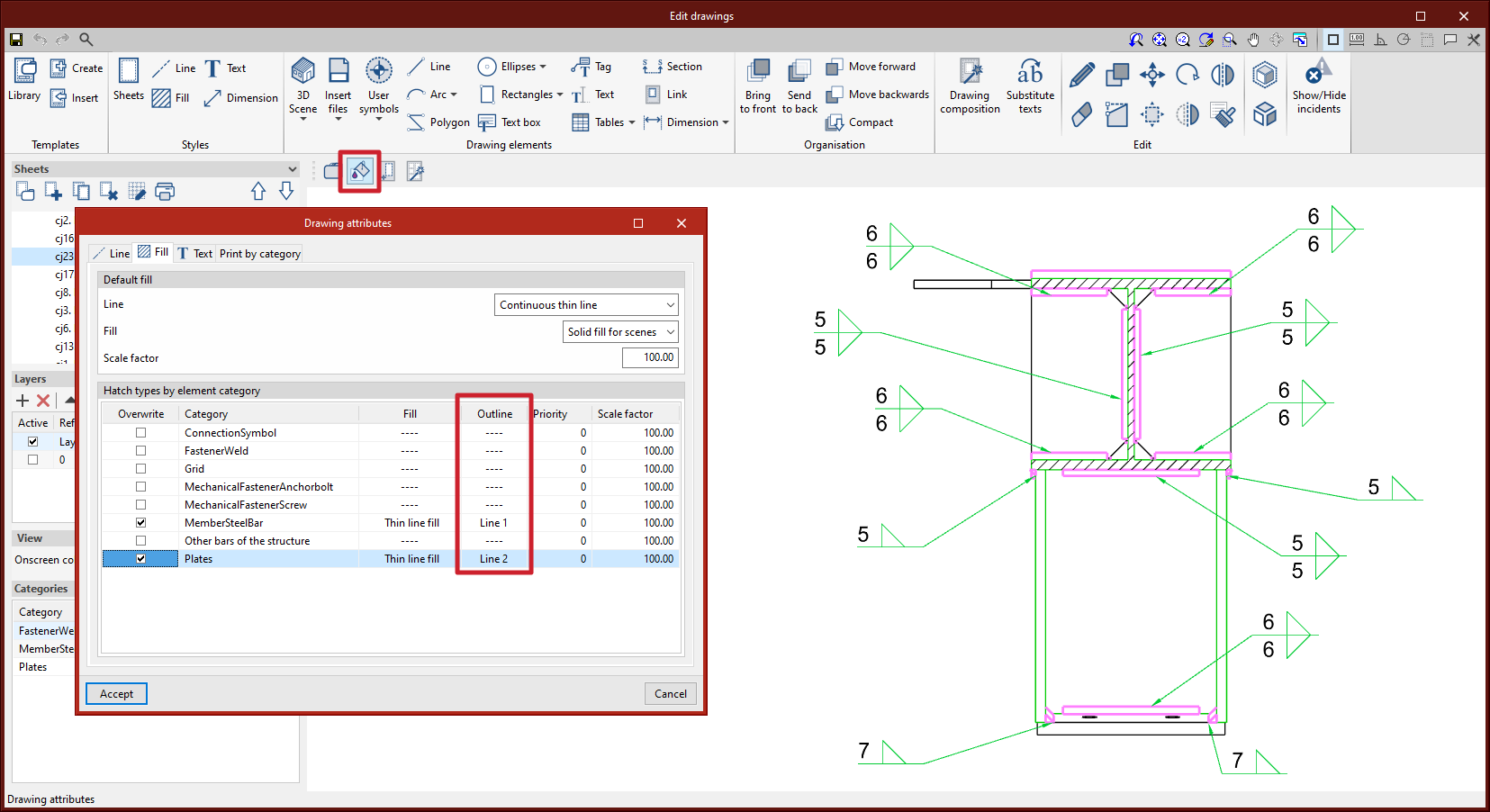
Editing the line style for the outline of section fills in scene views |
|
|
In version 2023.d, the editing of the line style for the outline of the section fills in scene views has been added. From “3D Scene” > “Drawing attributes” > “Fill”, users can access the dialogue box that allows them to edit the line style by category. |
|
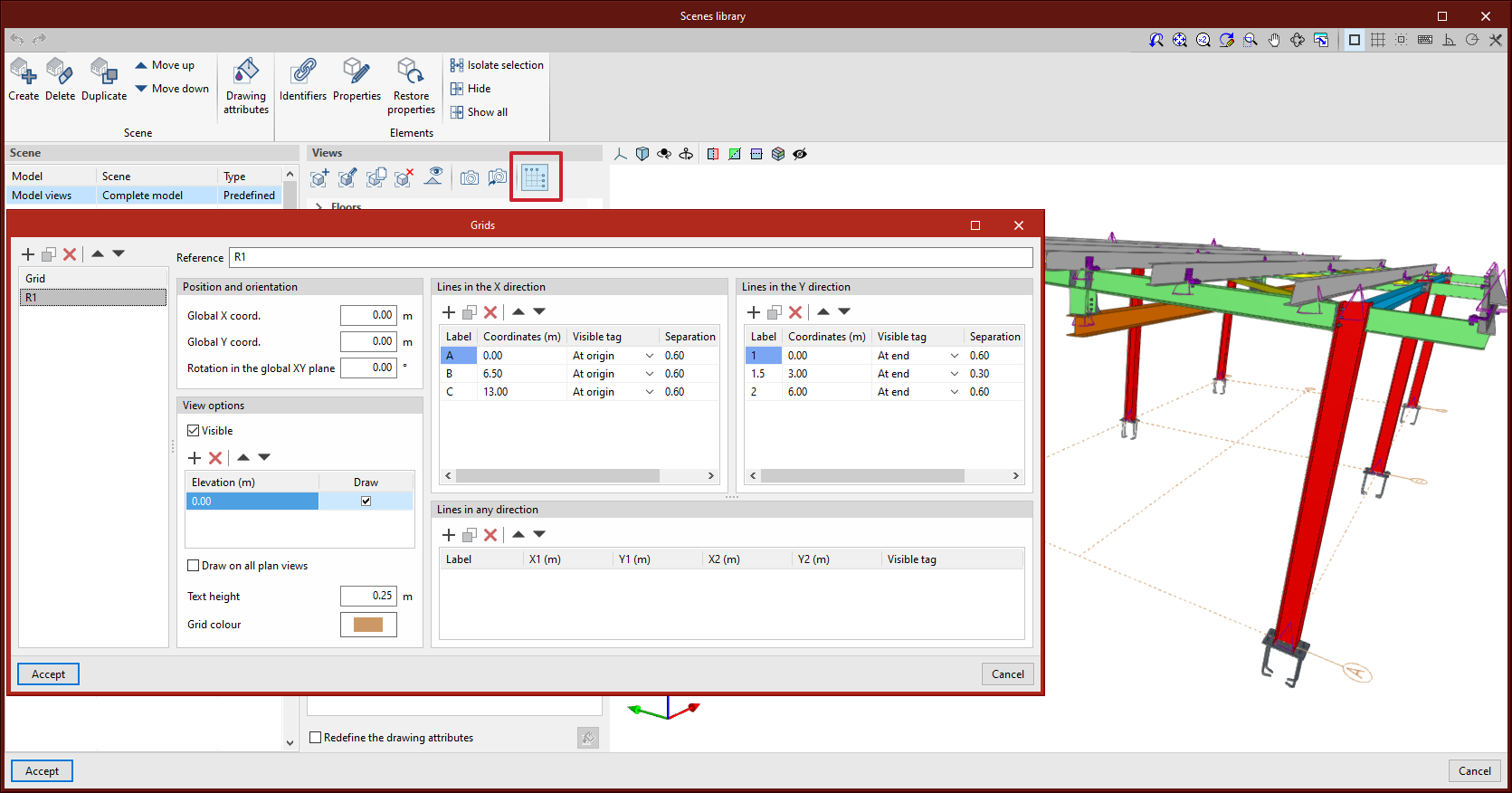
Grid editing by scene view |
|
|
As of version 2023.d, scene views can include grids. These grids can be edited from the scenes library. In StruBIM Steel, scenes in model views will automatically include the grid if it has been defined in the model. |
|
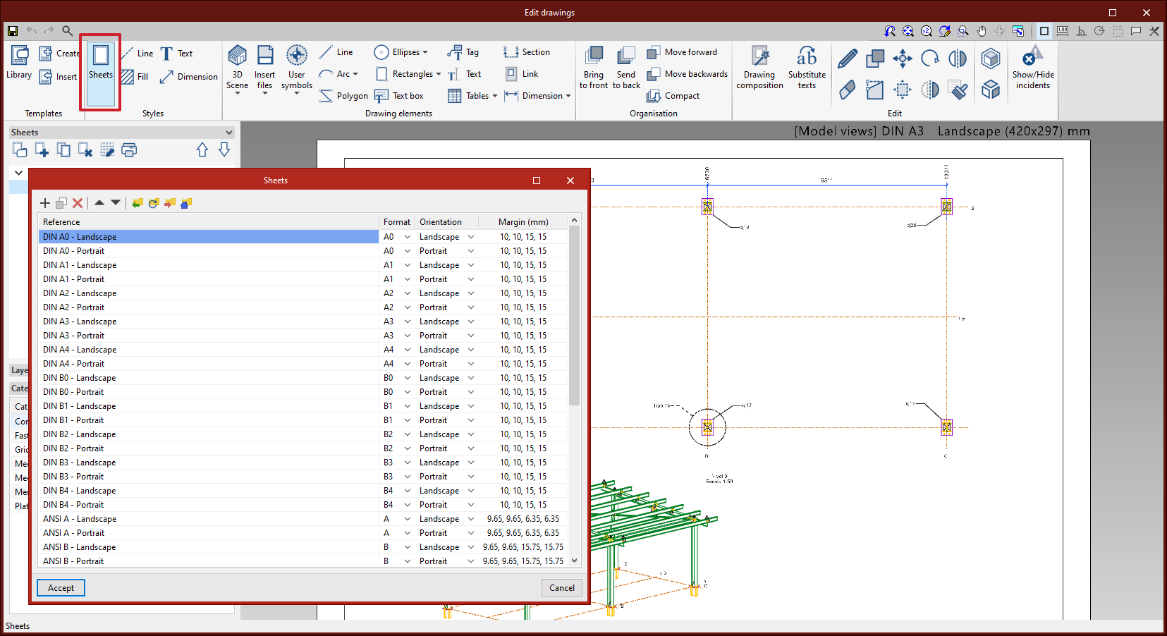
Sheet style |
|
|
The editing of sheet styles has been added. From “Styles” > “Sheets” you can control the orientation and margins of each sheet format. |
|
Pinned menu bars |
|
|
Options that used to display submenus in previous versions now feature a pinned toolbar. |
|

Regenerating scene views
As of version 2023.d, after scenes have been edited in the scenes library, only the affected scene views on the current sheet are regenerated.
StruBIM Steel / CYPE Connect
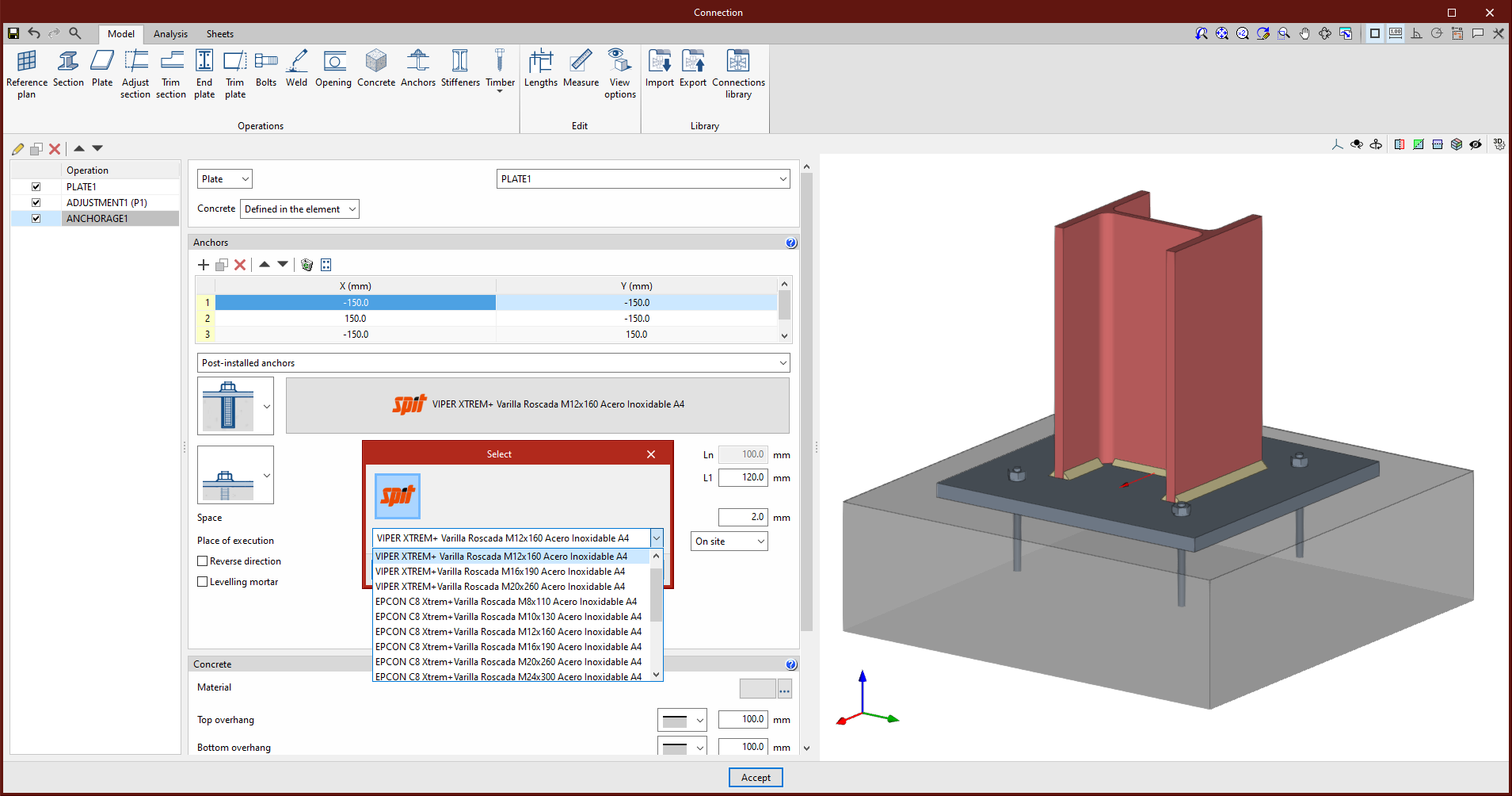
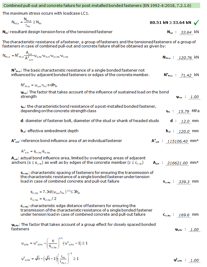
SPIT brand chemical anchors for concrete fixings
In version 2023.d of CYPE Connect and StruBIM Steel, SPIT brand post-installed chemical anchors can now be used as concrete fixings in baseplates. These elements are checked in accordance with the criteria of the EN 1992-4:2018 code, based on the data provided in the ETAs of these anchors (European Technical Assessment).
Improved clash detection |
|
|
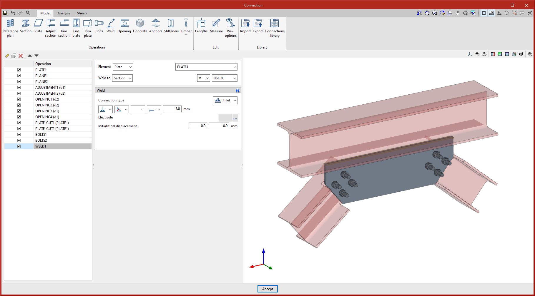
Clash detection between plates and sections has been improved. In previous versions, clashes between plates were detected as those that occurred in areas where an opening was placed. As an opening has been provided, the program no longer considers them as clashes because they do not represent a real situation. This allows users to model connections such as the one in the attached image. Furthermore, as an improvement in clash detection, clashes between overlapping plates are detected. |
|
Improved opening introduction |
|
|
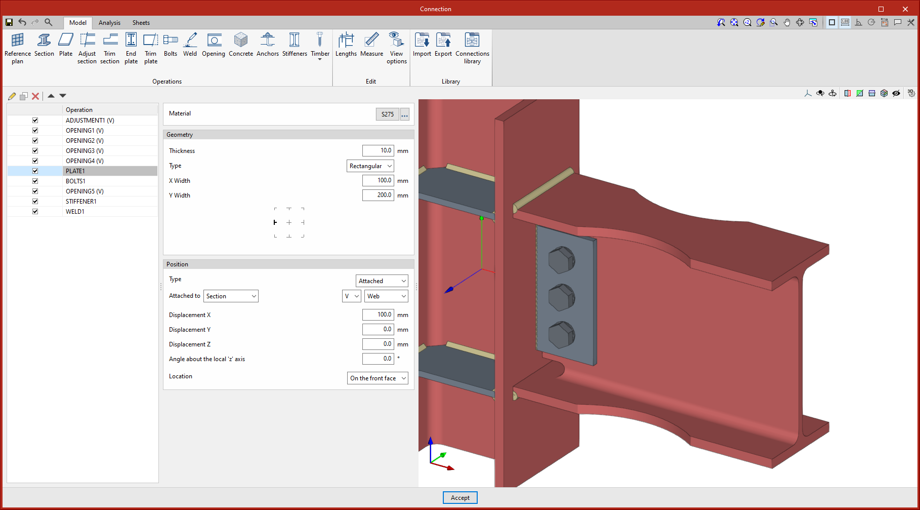
Up until the current version, connections could be analysed when the openings in plates or sections were internal, i.e. when they were completely contained in the plates. As of version 2023.d, openings can now intersect with the edges of the plates. |
|
Improved weld generation
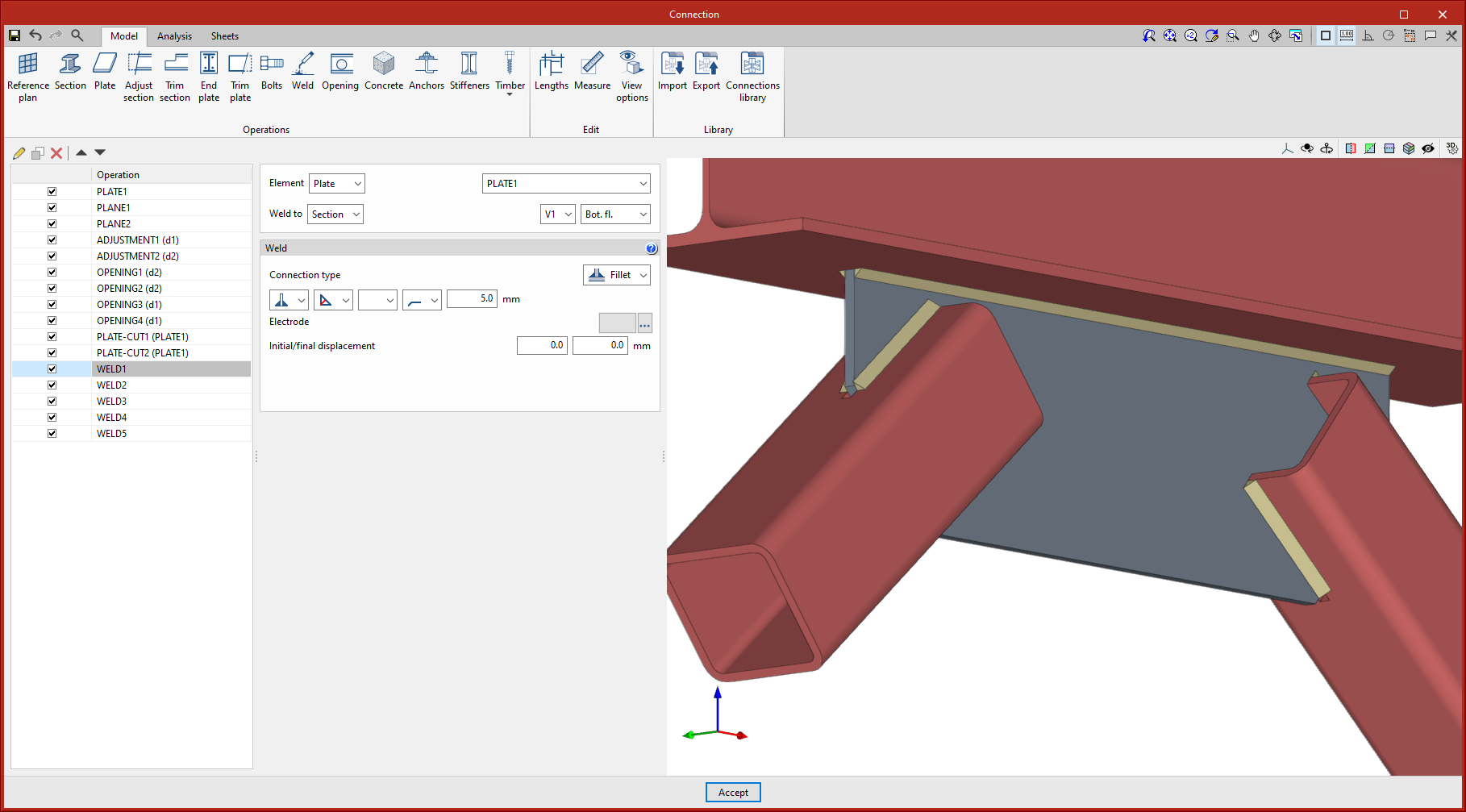
As of version 2023.d, welds can be applied to the internal contours of openings. This improvement, together with the improvements in clash detection and opening introduction, allows users to design and size connections with fitted plates, bars crossing openings, etc.
Automatic tagging of the type of electrode used in welds |
|
|
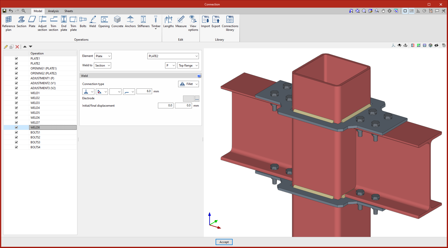
As of version 2023.d, in the notes section, the automatic weld tag now includes the reference of the electrode used as long as it has been defined in the operation where the weld is generated. |
|

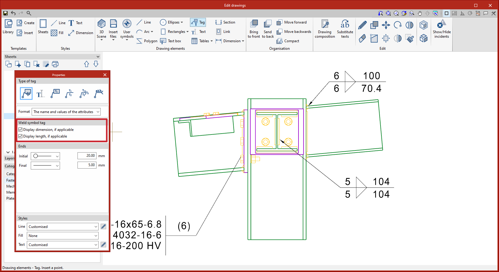
Options for displaying weld length and dimension on weld tags |
|
|
Weld tags display information about the welds in the model. Tags can be fully edited once entered, however, when entering tags, users are given the option to display or hide the dimensions and length, if applicable. |
|
Connection symbols in drawing layouts |
|
|
In version 2023.d, connection symbols are included in the “Drawing composition” in order to label the connections in the views of the structure. The connection symbol can be snapped with the “Tag” tool. The automatic tag will display the connection reference. The connection symbols will not be printed by default, however, users can manage this printing (see the new feature “Print management by categories of elements“). |
|
StruBIM Steel
Structural steel detailing drawings (new module)
In version 2023.d, the tools required for generating graphical documents of the structure have been added. Using these tools, users will be able to create sheets of the parts (sections and plates), assembly sheets, joint sheets and sheets with the general model views. The “Generation options”, “Parts”, “Assemblies”, “Joints”, “Model views”, “Composition” and “List” tools can be accessed from the “Sheets” menu.
These tools are included in the new StruBIM Steel module “Structural steel detailing drawings” and require the user license to have the corresponding permission for this module.

Generation options
The generation options are arranged in a dialogue box with four tabs (“Parts”, “Assemblies”, “Joints” and “Model views”), which have both common and specific options.
|
|
|
|
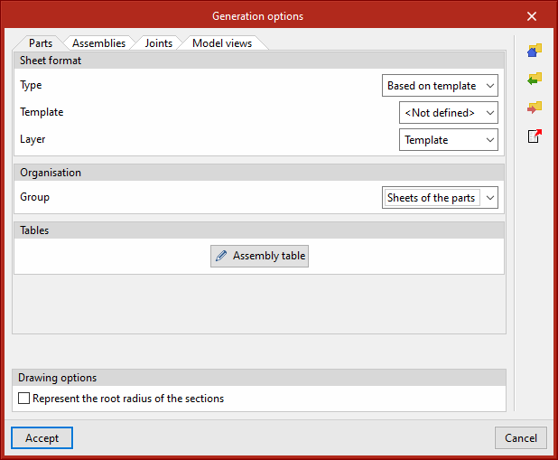

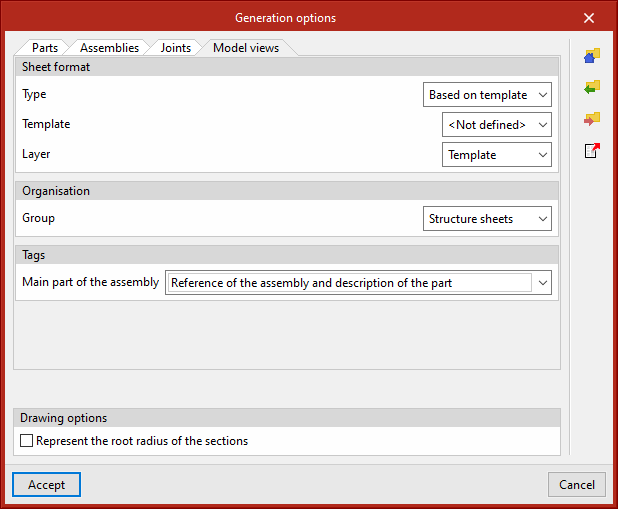
-
Sheet format (included in the four tabs)
Allows the format of the new sheets to be selected. In “Type”, users can select “Empty” together with the sheet format or “Based on template” together with the selection of one of the user-created templates and the layer. The template has a sheet format associated with it. -
Organisation (included in the four tabs)
Allows the group of sheets to be selected in which the newly created sheets will be generated. -
Tables (included in the four tabs)
Allows the formatted text of the predefined tables in the tabs to be selected. -
Drawing options (included in the four tabs)
In this section, the option for displaying the chord radius of the sections can be found. This option is deactivated by default.

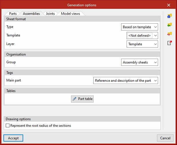
-
Tags of the “Assemblies” and “Model views” tabs
Allows the information that will appear on the automatic tags in the main part of the assembly to be selected. -
Number (“Joints” tab)
Allows a prefix to be defined for numbering the joints. -
Tags in the “Joints” tab
Allows the information that will appear on the automatic tags of sections and plates to be selected.
All generation option settings can be saved in the user library. User libraries can be managed via the options buttons on the right-hand side of the “Generation options” dialogue box.
|
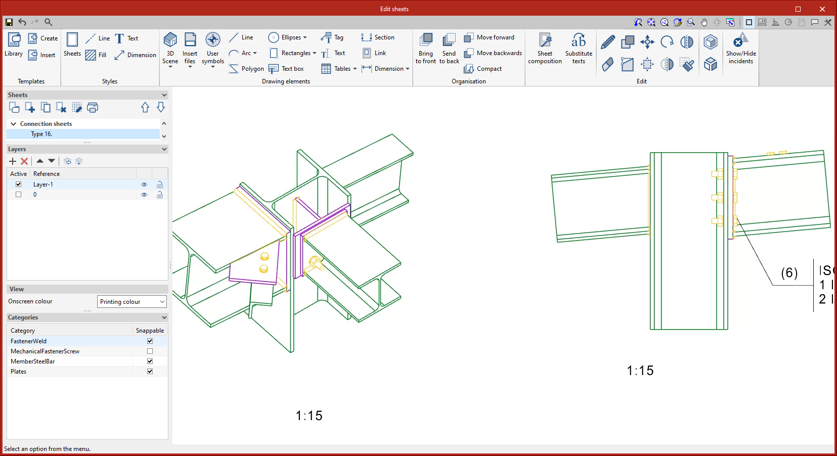
Parts This tool provides access to the drawing and editing panel of the sheets of the parts of the selected element. In the sheets of the parts, only one element (section or plate) is shown and its geometry is graphically documented. In these sheets, the predefined table of uses of the part in assemblies can be entered. |
|
|
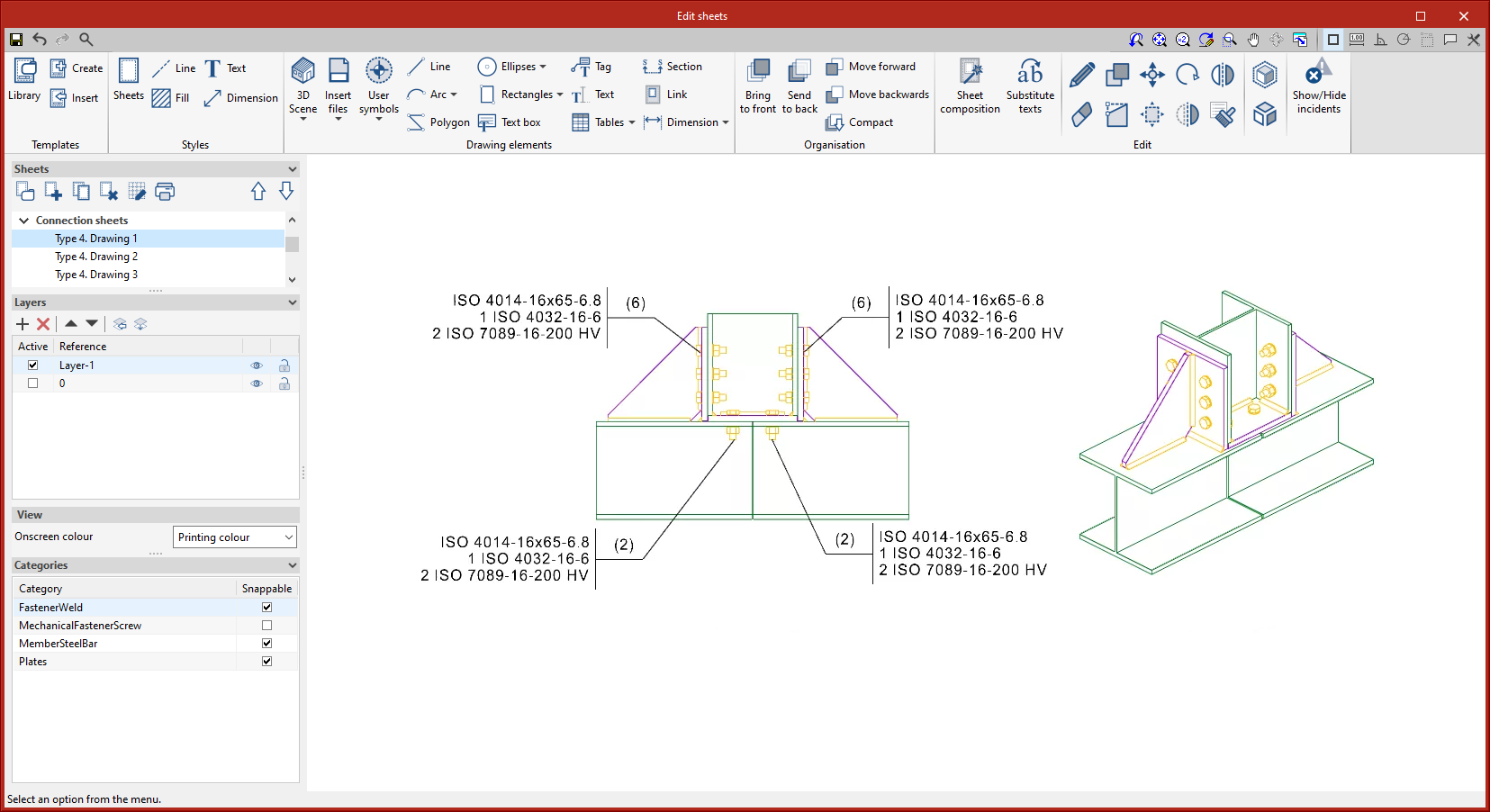
Assemblies This tool provides access to the drawing and editing panel of the assembly sheets of the selected element. The assembly sheets show all the elements (sections, plates, welds, bolts or anchors) that are part of the assembly being assembled in the workshop. In these sheets, the predefined table of the parts of the assembly can be entered. |
|
|
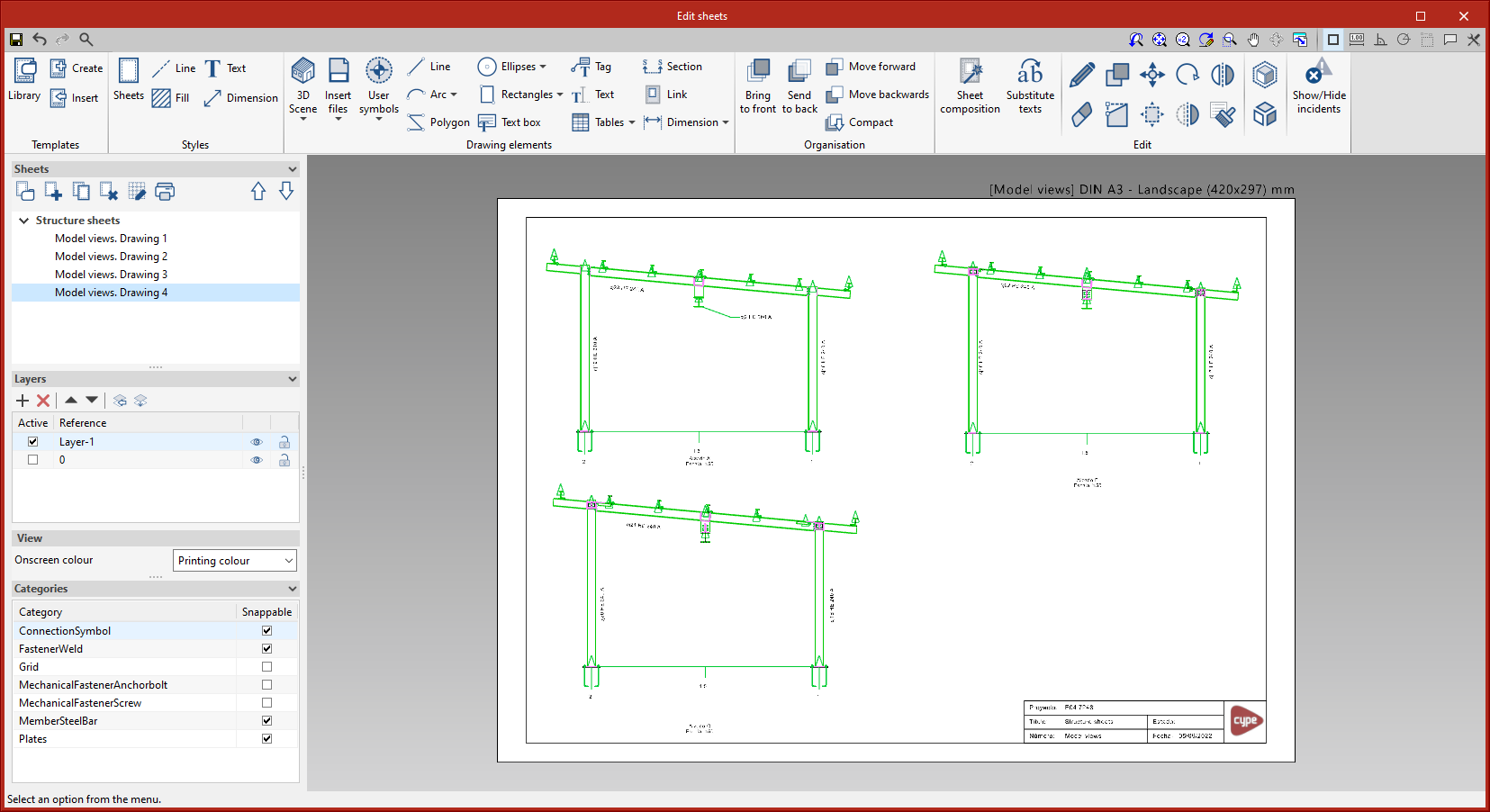
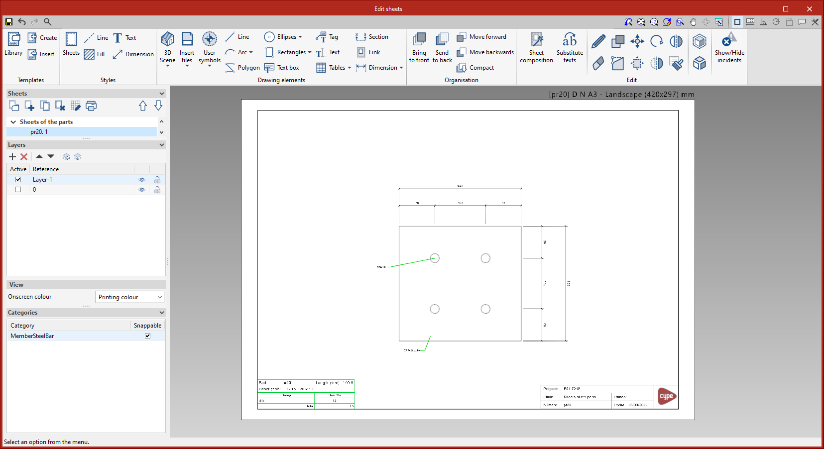
Joints This tool provides access to the drawing and editing panel of the joint sheets of the selected element. |
|
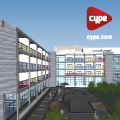
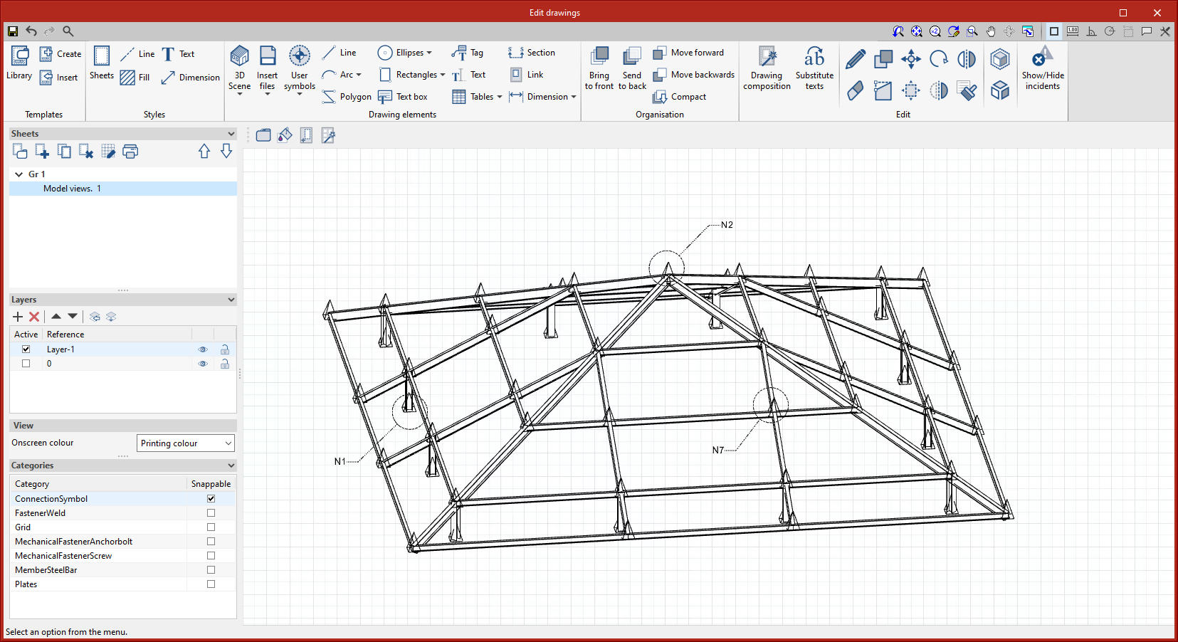
|
Model views This tool provides access to the drawing and editing panel of the model sheets, where the different views of the structure will be drawn. |
|
|
Composition From the “Composition” level, sheets can be created from other sheets, i.e. sheets made up of a composition of drawings from different elements. The “Link” tool allows a reference to the content of one sheet to be inserted into another, while the “Sheet composition” tool generates a mosaic with the selected sheets. |
|
|
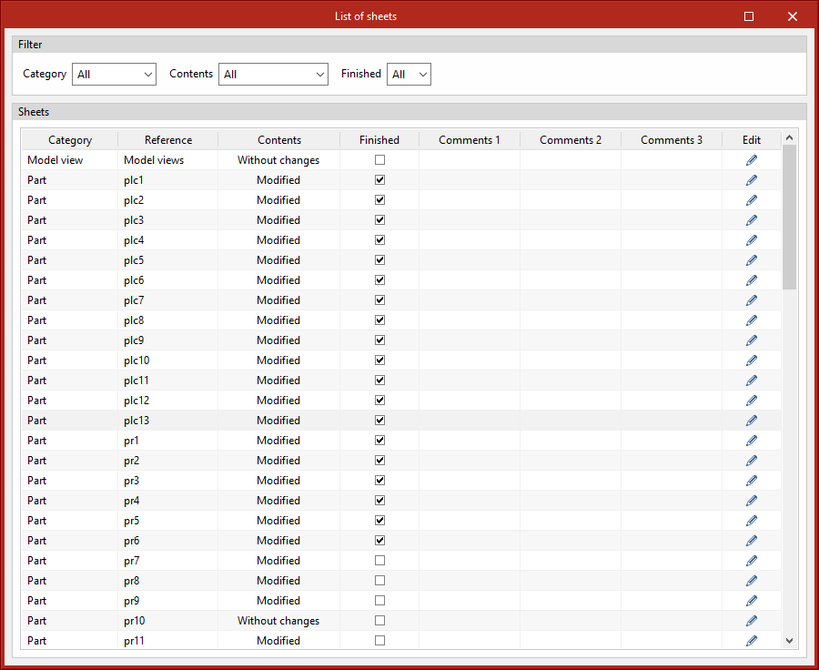
List In the “List of sheets” dialogue box, a list of all the sheets in the structure is displayed. From the list, the content of each sheet can be accessed by clicking on “Edit”. The list allows the content to be filtered by category, content type and completion status. The columns “Finished”, “Comments 1”, “Comments 2” and “Comments 3” allow users to add notes or comments to each sheet, as well as to mark them as finished when they consider it so. |
|


Improvements in the “Copy” tool
As of version 2023.d, the “Copy” tool will also copy the connections applied to the bars that are being copied. In previous versions, single elements (bars, plates, etc.) could be copied but, when this was done, the applied connections were not copied.
Managing tags from the sidebar |
|
|
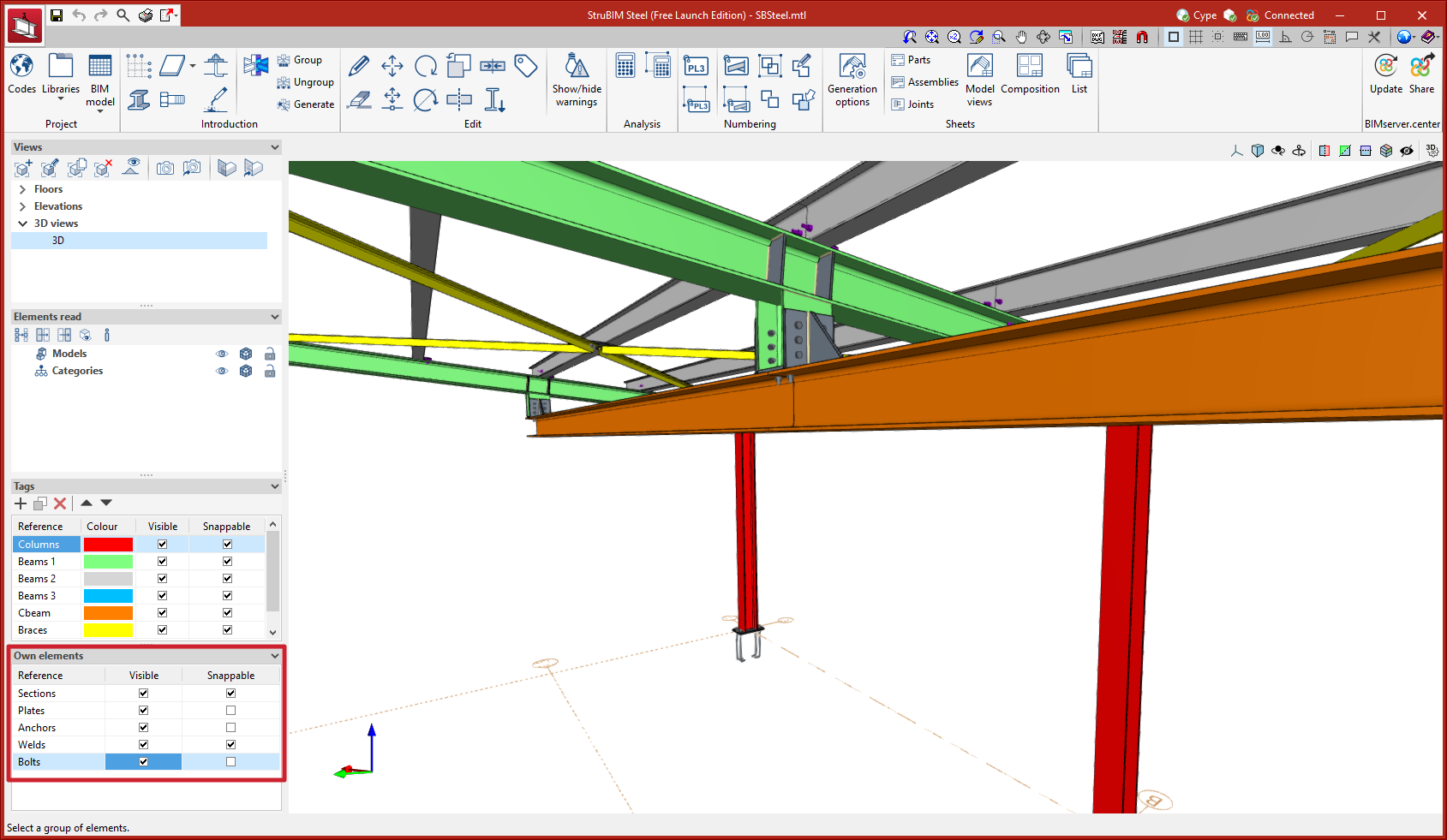
In previous versions, tag management was carried out by accessing a specific dialogue box from the options bar. As of version 2023.d, tag management is now located in the sidebar. This improvement allows quick access to commonly used commands such as activating or deactivating the view, creating new tags or deleting them and activating or deactivating snaps. |
|
Managing visibility and snapping by elements from the sidebar |
|
|
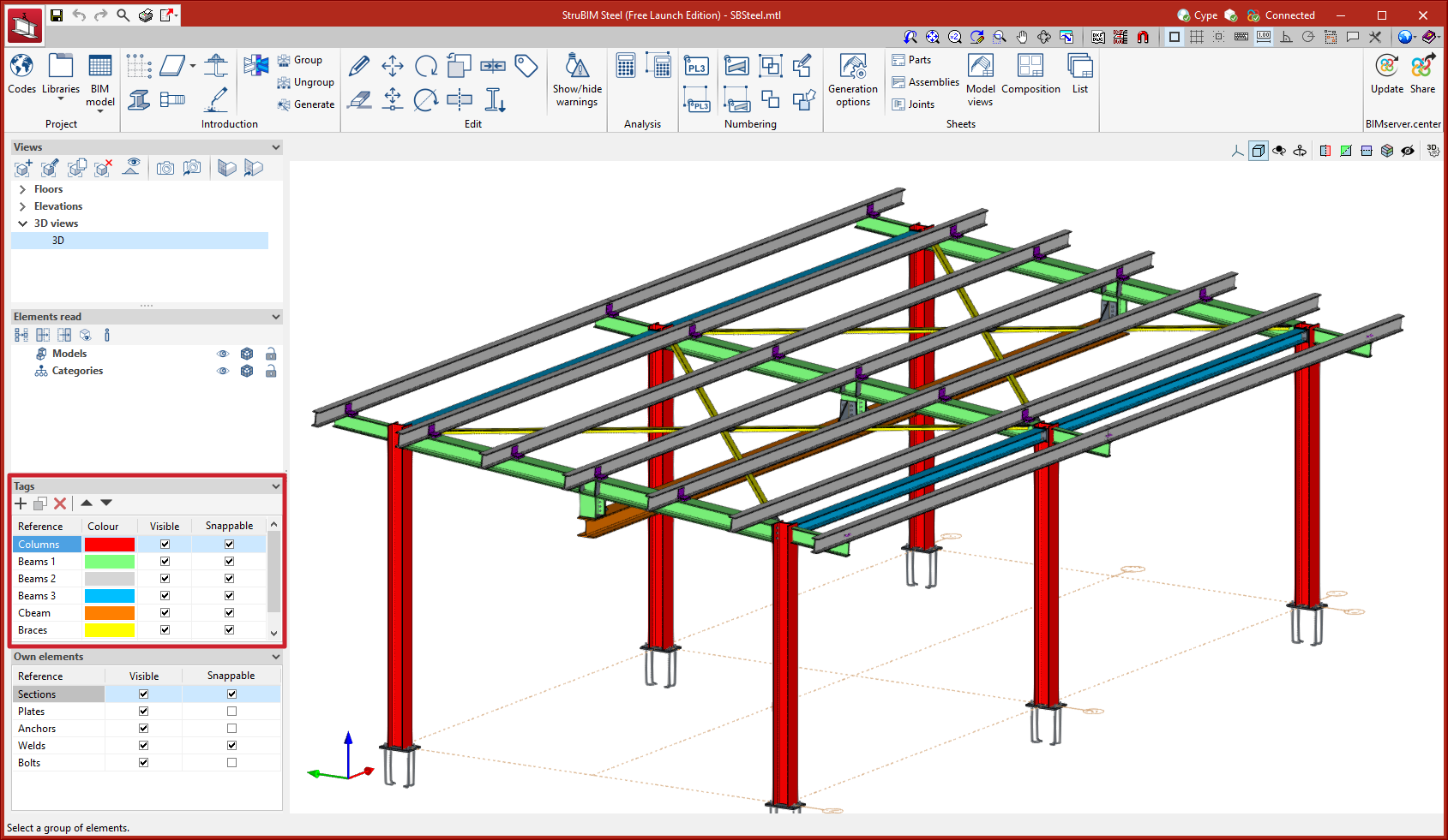
In previous versions, the management of visibility and snapping by elements was carried out by accessing a specific dialogue box from the options bar. As of version 2023.d, this management is located in the sidebar, allowing quick access to these commonly used tools. |
|
Rearranged option bar |
|
|
The existing options together with the newly implemented tools are placed from left to right following the order in which they will commonly be used as the project develops. Predefined connections, that existed until version 2023.c, will disappear in version 2023.d. From this version onwards, the connections between bars will be carried out using the “Connections” tool located in the “Introduction” menu. |
|
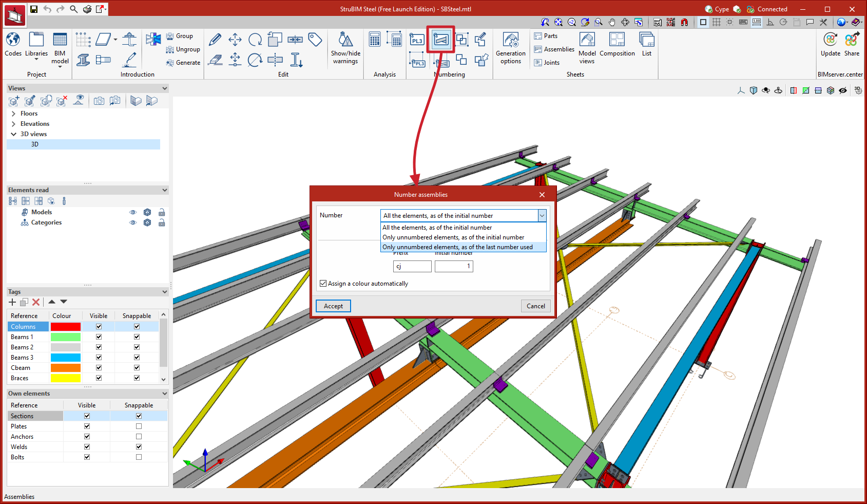
Numbering options
In version 2023.d the numbering tools for parts and assemblies have been improved. These tools search for matching elements and assign a number to them. With this new implementation, the grouping of equal elements is improved.
Three numbering options have also been added:
- Number “All the elements, as of the initial number”.
- Number “Only unnumbered elements, as of the initial number”.
- Number “Only unnumbered elements, as of the last number used”.

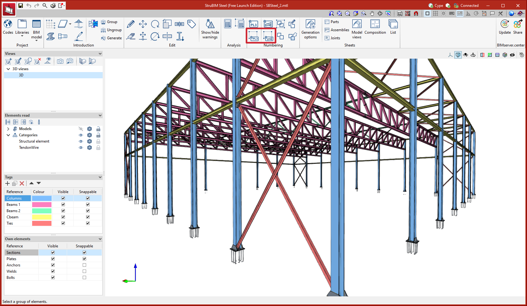
Tools for numbering a selection of elements |
|
|
Two new tools have been added for numbering a selection of elements:
These tools only number selected elements, which allows users to number elements according to their own criteria, by floors, zones, phases, etc. |
|
Selecting the main part of the assembly
The tool for selecting the main part of an assembly has been added. These are the steps to follow:
- Select the assembly.
- Select the main part of the assembly.
The orientation of the assembly views in the sheets shall be that of the main part. In the sheets of the complete model, the assemblies may be tagged by adding the description of the main part.
Automatic grouping of assemblies according to the place of execution of welds, bolts and anchors
Up until version 2023.d, elements added from the connection editor were not grouped into assemblies. As of version 2023.d, elements that are connected by means of welds or bolts executed in the workshop will be grouped together to form workshop assemblies. When the construction site is defined as the place of execution, the elements will not be grouped together.
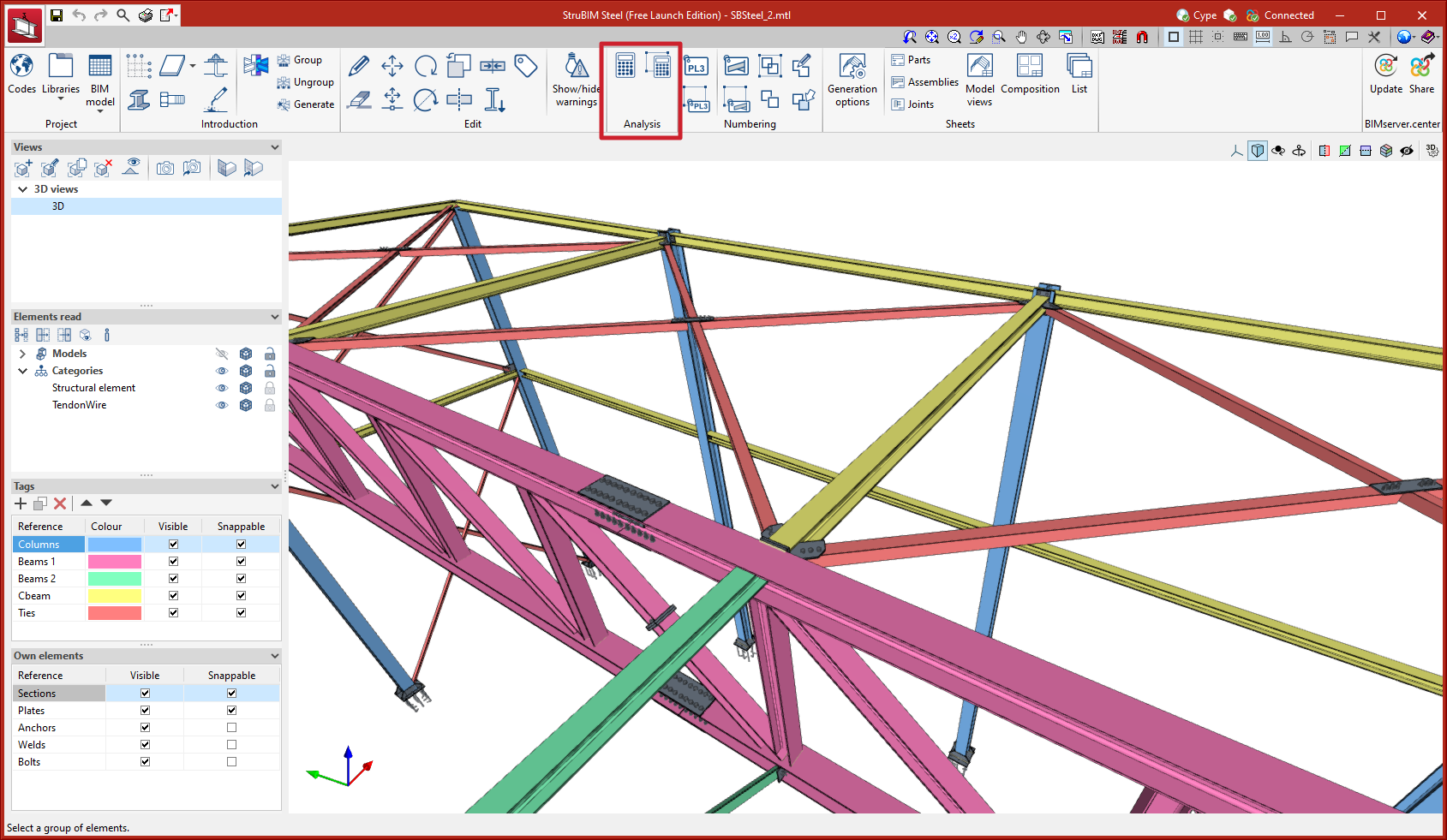
Analysing multiple connections |
|
|
Two new options for analysing multiple connections have been added. These options, similar to those that were added in CYPE Connect version 2023.c, allow users to automatically analyse multiple connections without the need to access each connection to then click on the ”Stress/strain” or ”Rotational stiffness” analysis options:
|
|
Options for grouping and generating nodes |
|
|
Options for managing groups of matching nodes have been added. Groups of nodes will be assigned the same connection. The connection assigned to a group of nodes will read the bar forces from all the nodes in the group from the BIM project. The combination filtering carried out from “Generate from BIM model” is based on the sum of the combinations of all the nodes. The options for managing these groups are:
|
|

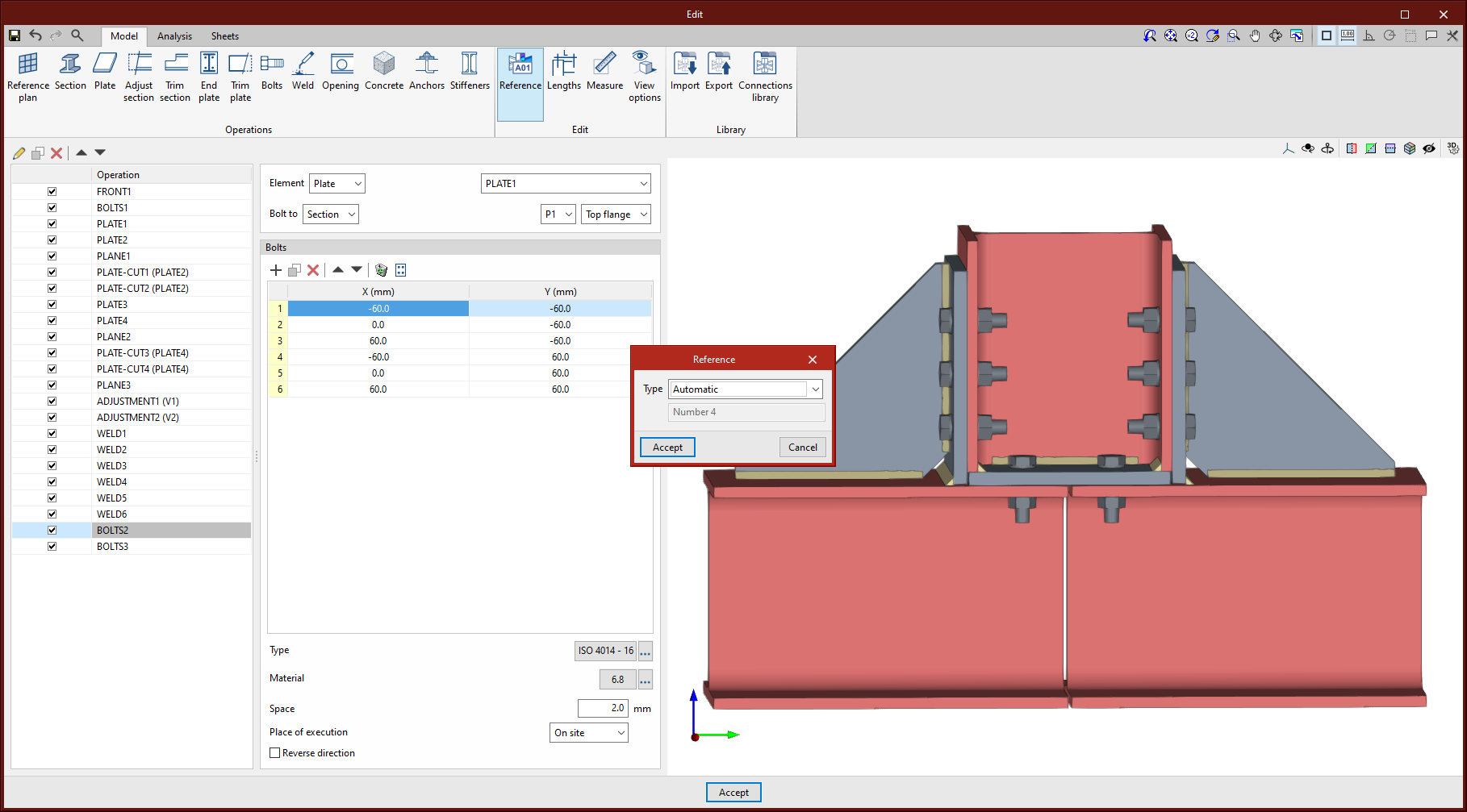
Editing the connection reference |
|
|
A connection reference editing feature has been added. This reference can be either automatic or user-defined. The automatic reference is composed of the prefix defined in the sheet generation options. |
|
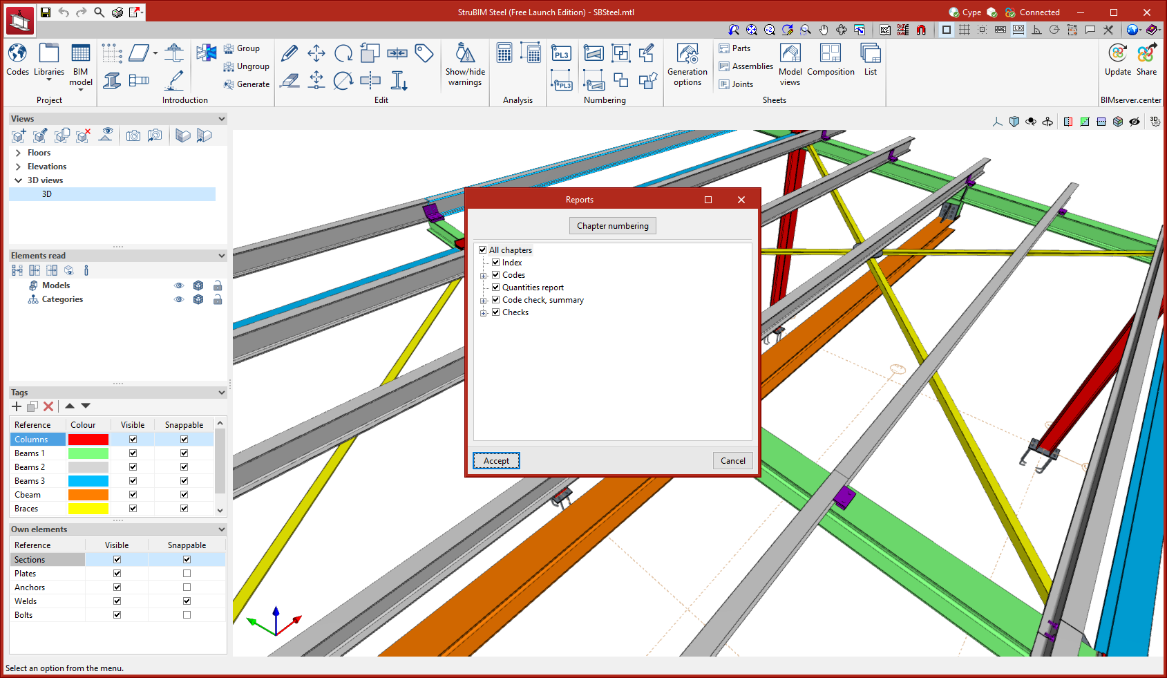
New report types |
|
|
New report types have been added for connections:
|
|
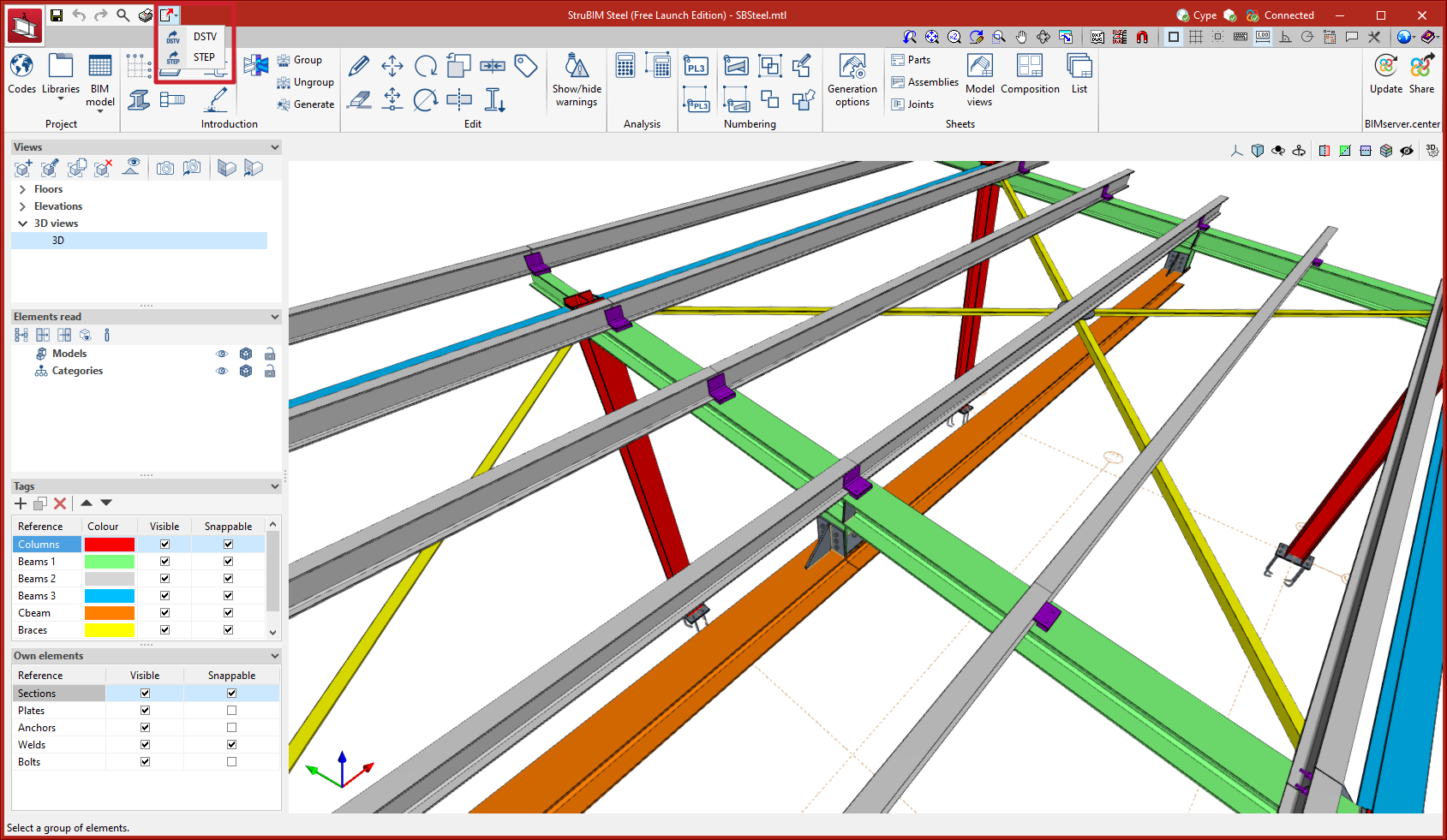
New menu option for exporting to DSTV and STEP formats |
|
|
Up until version 2023.d, the options for exporting to DSTV and STEP formats were found in the “Share” tool located in the BIMserver.center tool group. As of version 2023.d, these options are also available from the “Export” button at the top left of the screen. |
|
Model update during editing
Automatic model update during the editing of bars (linear elements) has been implemented. As of version 2023.d, once a bar has been edited, any affected connections will be updated automatically.
StruBIM REBAR
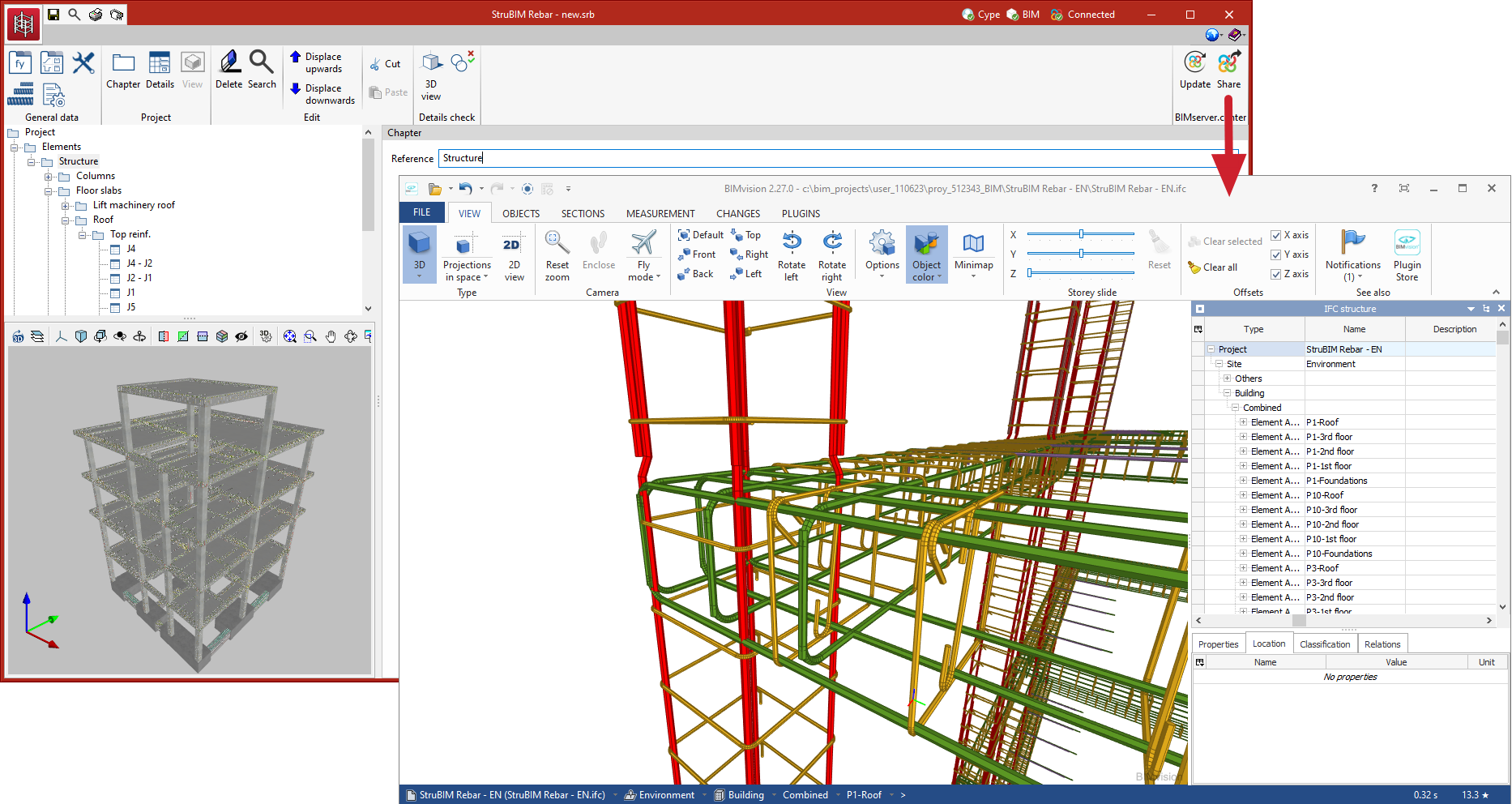
Exporting to IFC format |
|
|
Users can now export the rebars of the project to IFC format. By means of this improvement, the reinforcement of a structure that has been designed and sized with CYPECAD, StruBIM Shear Walls, or StruBIM Embedded Walls can be shared with other programs. |
|
CYPEFIRE
Installation in French, English and Portuguese
In previous versions, CYPEFIRE could only be installed in Catalan and Spanish. As of version 2023.d, CYPEFIRE can also be installed in French, English and Portuguese.
Report design |
|
|
In order to present the best possible project, report configuration and editing are essential. With CYPEFIRE, improving and modifying the information obtained is now extremely easy. Options for configuring the reports can be found in the “General options” menu in the top toolbar. “Report design” currently allows the main reports of the program to be edited:
For these 6 reports, users can enter additional information about the program’s original chapters or create new chapters with their own descriptions. |
|

CYPEFIRE / CYPELUX
CYPEFIRE communication with CYPELUX
As of version 2023.d, CYPEFIRE can share evacuation routes and required fire safety equipment so that CYPELUX can design the required emergency lighting in the BIM project.
CYPETHERM LOADS
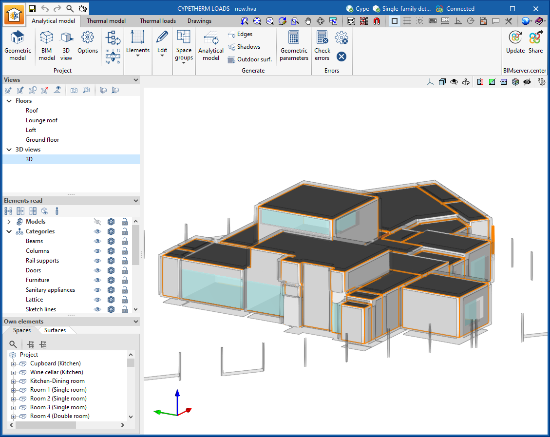
Open BIM Analytical Model integration
|
As of version 2023.d, CYPETHERM LOADS now includes all the Open BIM Analytical Model tools in its new “Analytical model” tab, allowing the analytical model of the building to be created and managed in CYPETHERM LOADS itself. |
|
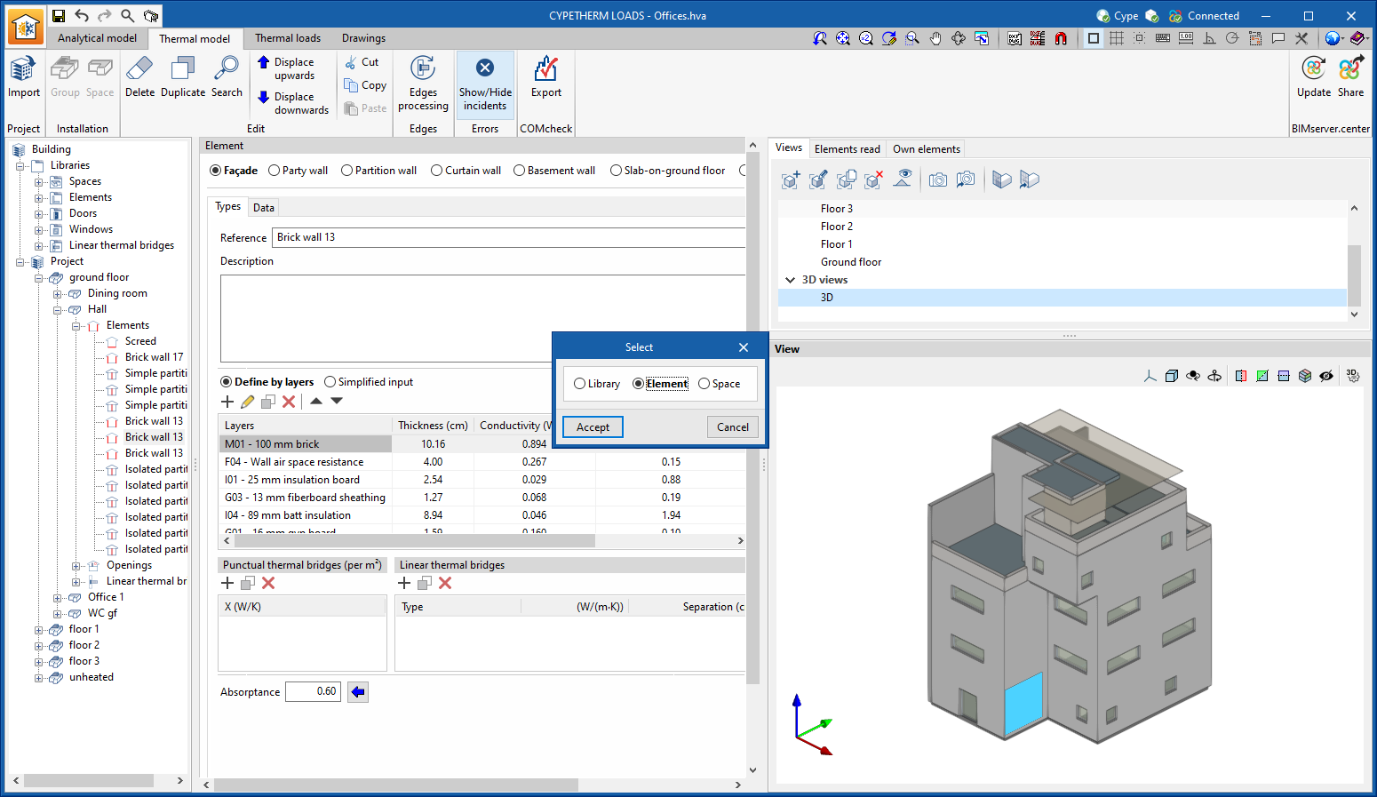
Redesign of the “Thermal model” and “Thermal loads” tabs
The “Thermal model” (called “Building” in previous versions) and “Thermal loads” tabs have been redesigned to improve user experience when defining and maintaining the building thermal model, as well as when analysing the results.
|
|
|
|

New “Drawings” tab
|
The “Drawings” tab has been included in the program. In this tab, users can create and edit the drawings of the thermal envelope used for each of the loadcases designed in the project. |
|

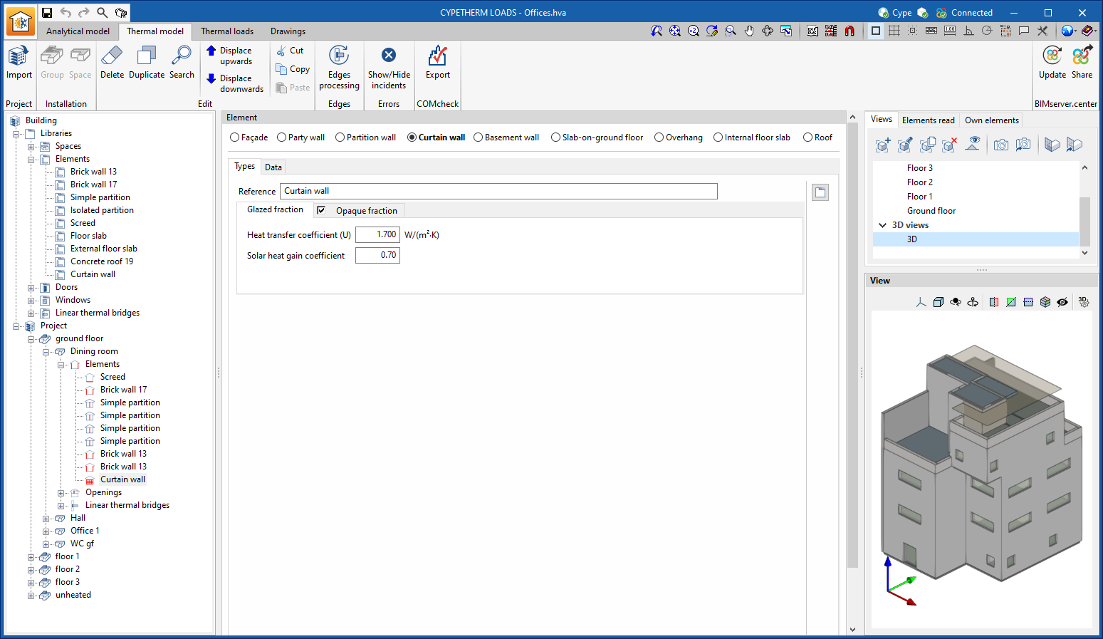
Curtain walls
|
Curtain wall systems can now be defined. To do this, the “Curtain wall” option is included in the elements library, which allows users to enter the thermal properties of the “Glazed fraction” and the “Opaque fraction” of a wall, in a similar way to the definition carried out for windows. |
|
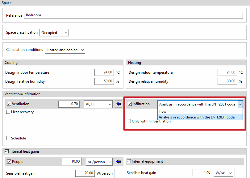
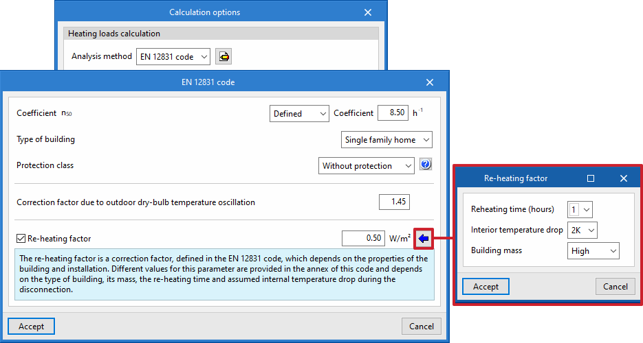
Improved data entry when the EN 12831 code is applied
|
The program allows users to select the infiltration analysis according to the EN 12831 code in the definition of the type of space. |
|
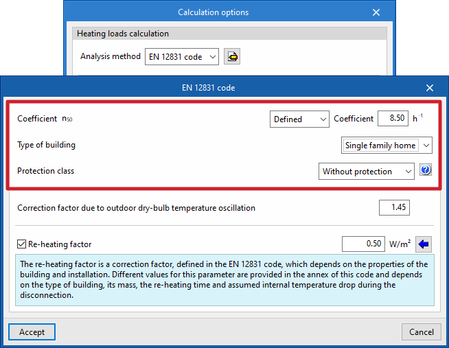
|
When the selected analysis method for heating thermal loads is the EN 12831 code, the program considers the parameters defined in the “Calculation options” panel to analyse the flow rate due to infiltrations: |
|
|
A wizard has also been added to make it easier to define the “Re-heating factor” parameter: |
|
Open BIM Quantities / Applications with a "Bill of quantities" tab
Improved "Zoom" tool
The option to “Zoom” into the 3D model element has been added in the following cases:
|
|
|
|
Applications with a "Bill of quantities" tab
Quantities on the 2D/3D model
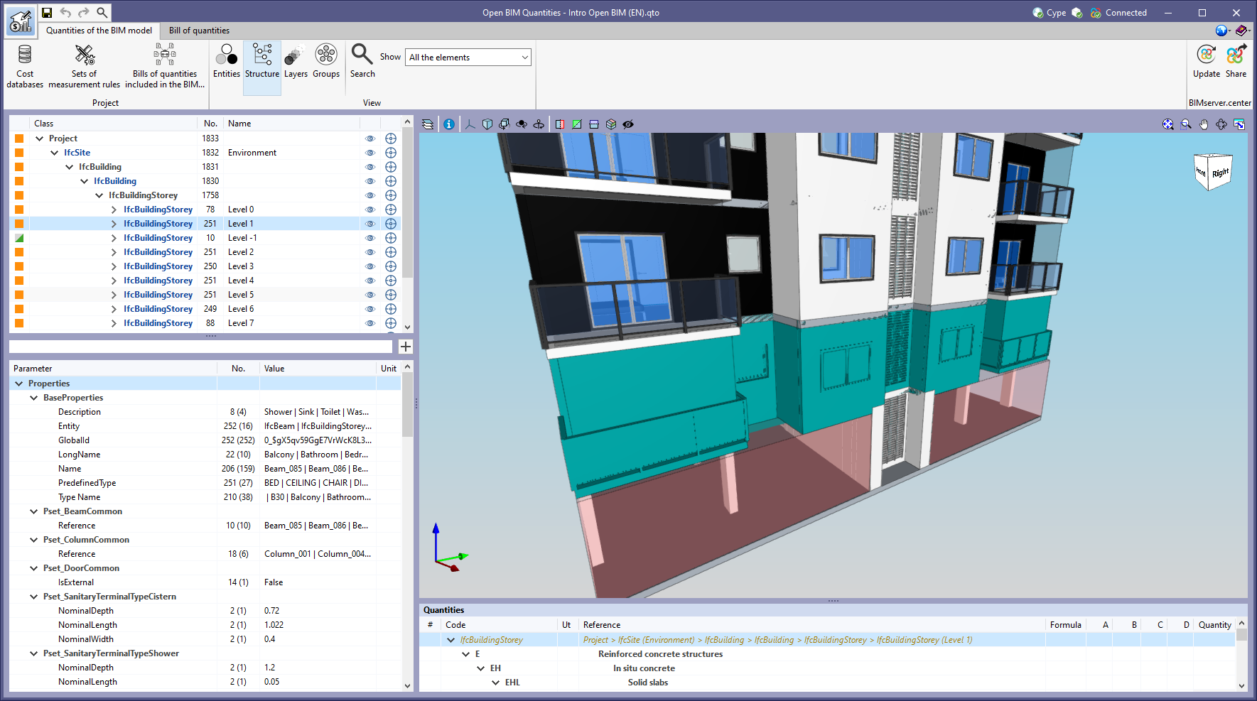
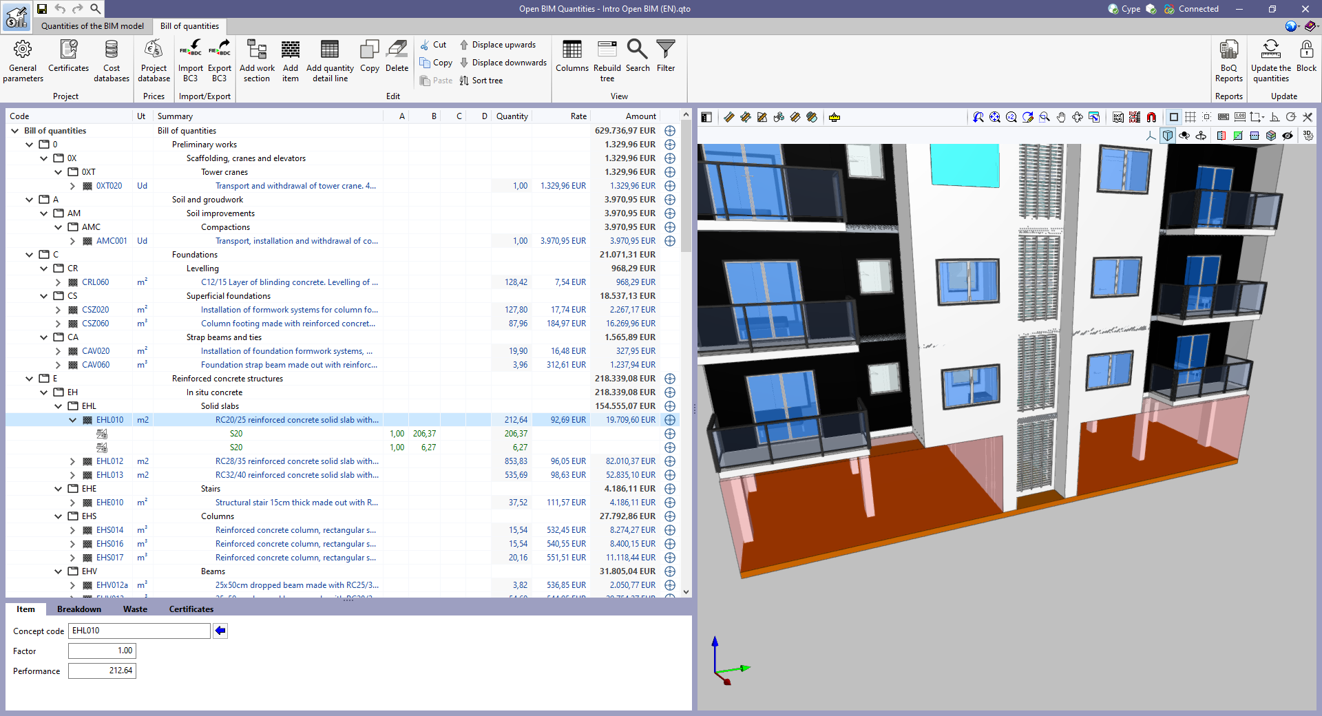
As of version 2023.d, all applications with a “Bill of quantities” tab now have a new set of tools that allow users to measure quantities in the work area. More specifically, the following options have been added:
|
|
|
|
In order to make it easier to measure the quantities of the model, the work area has been modified to incorporate the 3D work environment tools that are already available in other CYPE Open BIM applications:
|
|
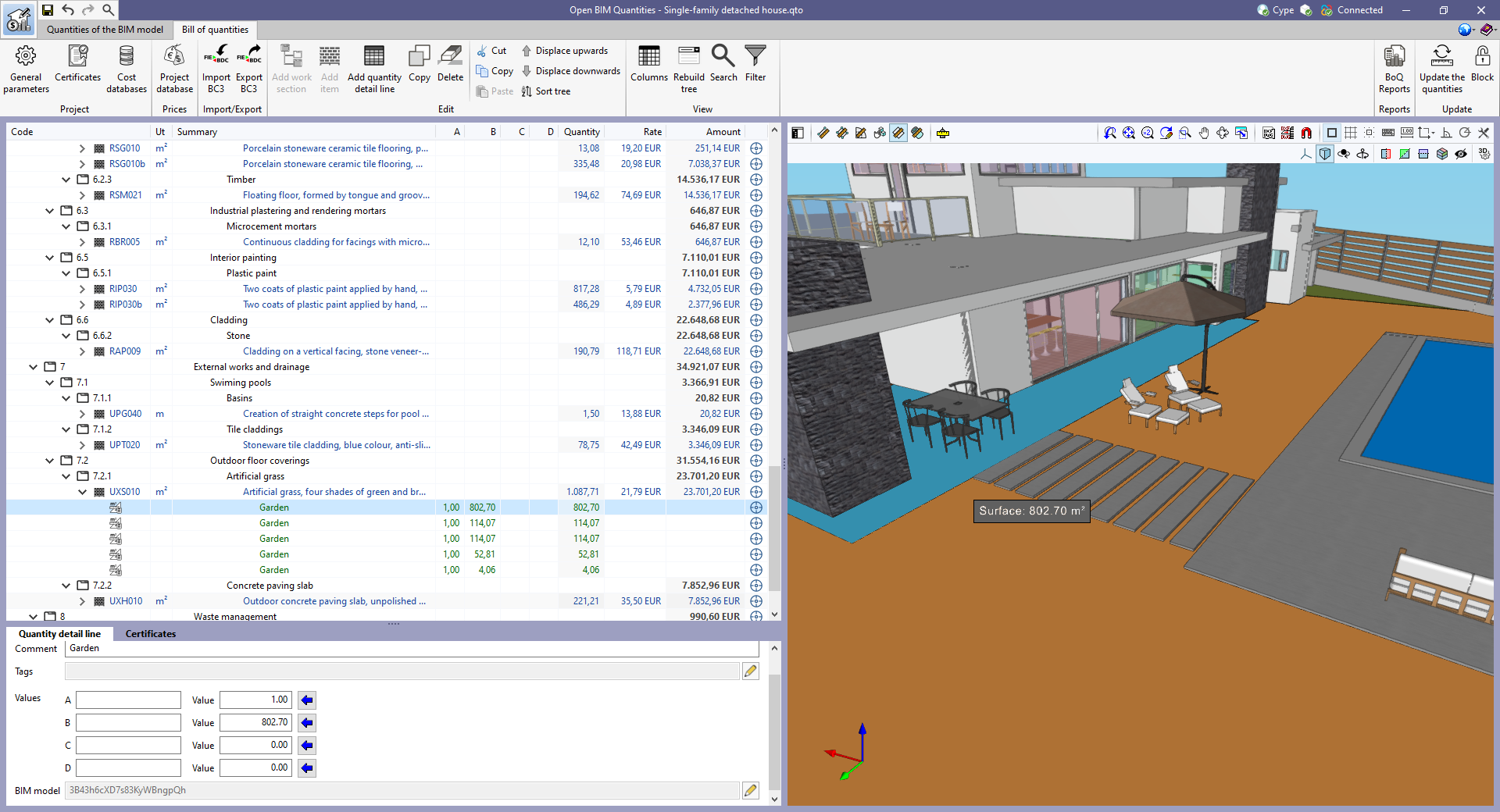
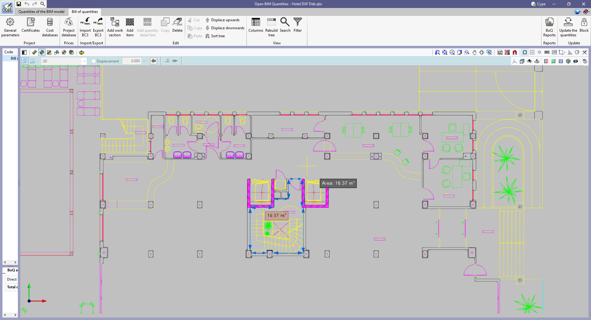
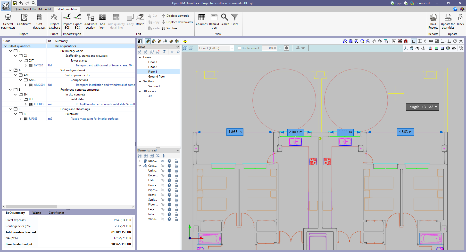
As well as measuring the 3D model, this new set of tools can be used to take measurements on plans or 2D drawings imported from CAD files (“.dxf”, “.dwg”, “.dwf”) or images (“.jpeg”, “.jpg”, “.bmp”, “.png”, “.wmf”, “.emf”, “.pcx”). These files and the object snaps are managed through the “DXF-DWG Templates” and “Template object snaps” options respectively.
|
In order to use the measurements in the project’s bill of quantities in a simple way, a button with a blue arrow has been added to the editing panel of the detail lines next to the editing window of each variable (A, B, C and D). Clicking it will assign the value of the measurement made on the work area to the variable. |
|

Return to the 2023 version download area
Tel. USA (+1) 202 569 8902 // UK (+44) 20 3608 1448 // Spain (+34) 965 922 550 - Fax (+34) 965 124 950