NEW FEATURES OF EXISTING PROGRAMS
- New features common to several programs
- Implementing codes and improving their enforcement
- CYPE Architecture
- IFC Builder
- Open BIM Site
- Open BIM Analytical Model
- CYPECAD and CYPE 3D
- CYPECAD
- CYPE 3D
- CYPE Connect and StruBIM Steel
- CYPE Connect
- CYPELEC Electrical Mechanisms
- CYPELEC Distribution
- CYPELEC PV Systems
- Maximum number of panels in the available roof surface area
- Automatically adapting panels into roofs using overlay or architectural integration
- Editable shade factor for each panel
- "Production summary" document
- Optimisation of the shading analysis process
- Option for calculating the energy produced using simplified shading diagram
- CYPETEL Schematics and CYPETEL Systems
- CYPELUX, CYPELUX EN y CYPELUX LEED
- CYPEHVAC Hydronics
- CYPETHERM EPlus
- Arquimedes
- Open BIM Quantities
NEW FEATURES OF EXISTING PROGRAMS
New features common to several programs
Bill of quantities tab
Rebuild tree
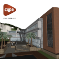
The "Rebuild tree" feature has been added to the toolbar of the "Bill of quantities" tab in the applications where this tab is included. This button is available in the main window of the "Bill of quantities" tab, as well as in the definition panel of the cost databases and prices of the job.
Thanks to this new feature, it is now possible to display or collapse the bill of quantities tree based on the type of items it contains. The reconstruction options allowed in this version are the following:
- Show only the first work section level
Only work section type concepts that derive directly from the root of the bill of quantities are displayed. - Only show work sections
All work section type concepts are displayed. - Show work sections and items
All work section type concepts and items are displayed. - Expand all
All the work section type concepts, the items and the detail lines they contain are displayed. For cost databases, the breakdown of the items is displayed instead of the detail lines.
Implementing codes and improving their enforcement
Rolled and reinforced steel structures
NTC-DCEA 2020 (Ciudad de México)
"Normas Técnicas Complementarias Para Diseño y Construcción de Estructuras de Acero (Ciudad de México, 2020)".
Implemented in CYPECAD and CYPE 3D.
PN-EN 1993-1-1:2006/NA:2010 (Poland)
Polish National Annex to Eurocode 3 (Design of steel structures - Part 1-1: General rules and rules for buildings).
Implemented in CYPECAD and CYPE 3D.
Cold formed steel structures
PN-EN 1993-1-3:2008/NA:2010 (Poland)
Polish National Annex to Eurocode 3 (Design of steel structures - Part 1-3: General rules - Supplementary rules for cold-formed members and sheeting).
Implemented in CYPECAD and CYPE 3D.
CYPE Architecture
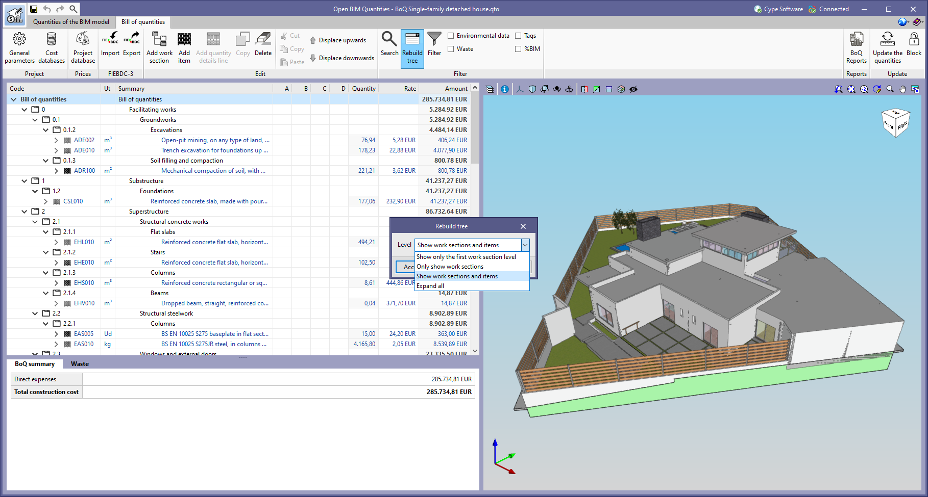
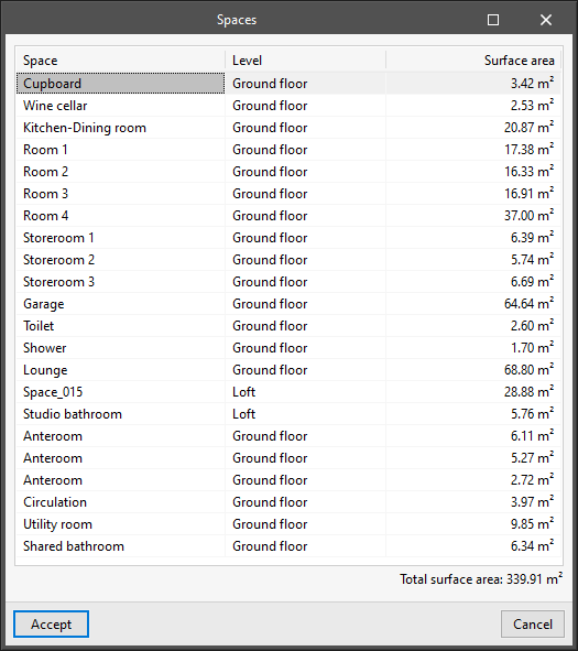
Spiral staircases
The program allows spiral staircases to be created in two different ways:
- Manually entering the data of the stairs and positioning them in the space.
- Directly drawing stairs based on their width and height.
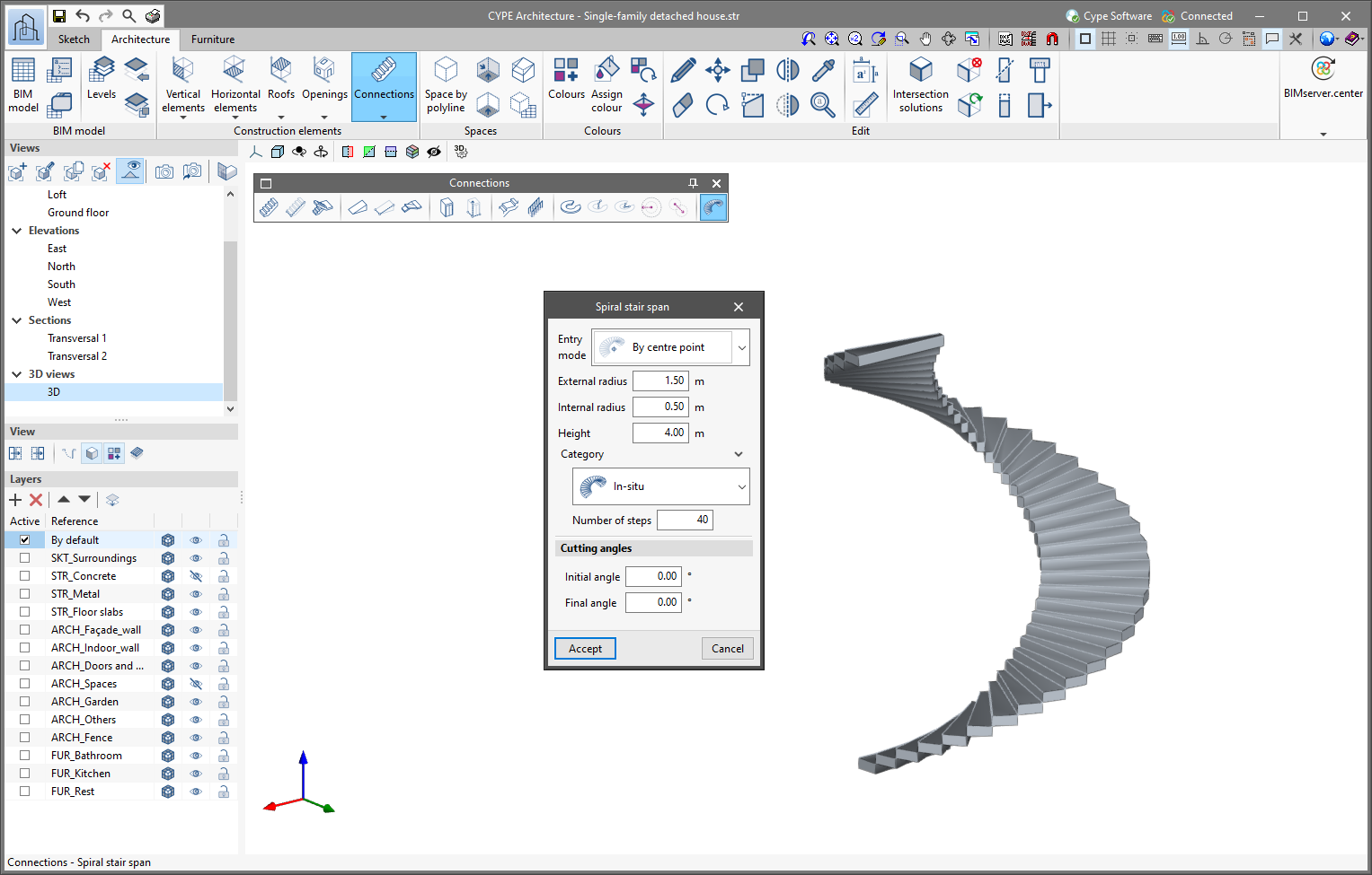
Surface table
The program includes a feature for generating a table for surfaces. This table allows the net internal area of each of the spaces in our model to be checked, and also displays its total net internal area.
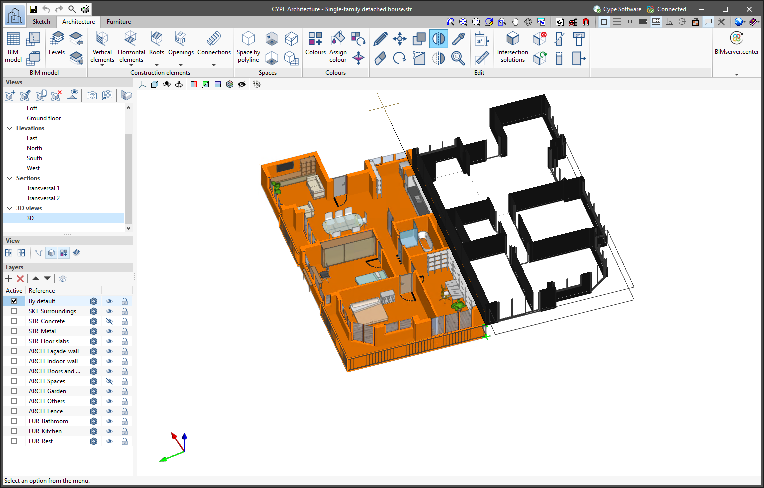
Move and copy with symmetry
This new feature allows architectural elements to be moved or copied by mirroring them symmetrically with respect to a specific line.
Improved level detection
Improvements in level detection have been included:
- CYPE Architecture automatically detects the level when furniture elements are introduced.
- The program automatically detects the level of architectural and furniture elements when using the move and copy tool.
CYPE Architecture manual in Portuguese
CYPE Architecture version 2022.f includes the program’s manual in Portuguese. It was already available in other languages in previous versions. The languages in which the CYPE Architecture manual is now available are the following:
"Office block" example
The example job "Office Block" has been translated into English, French and Polish.
IFC Builder
Exporting new quantities to IFC files
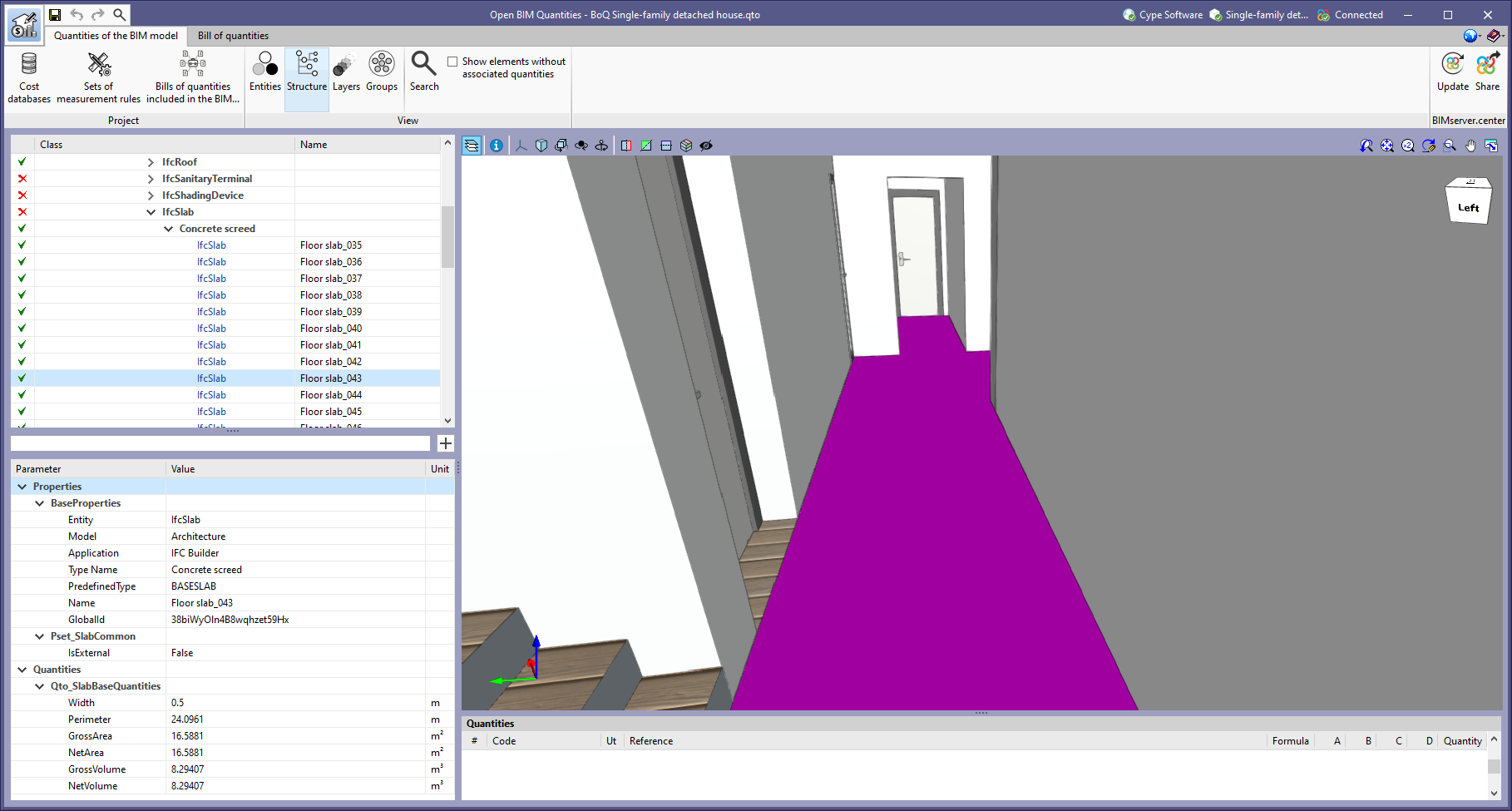
As of version 2022.f, IFC Builder includes the following base quantities for its corresponding IFC entities in the IFC file that it exports to the BIMserver.center project:
- Screed and Internal floor slab ("Qto_SlabBaseQuantities")
- Width
- Perimeter
- Gross Volume
- Net Volume
These new quantities can be used in the Open BIM Quantities application for estimating the quantities and cost estimations of the architectural model.
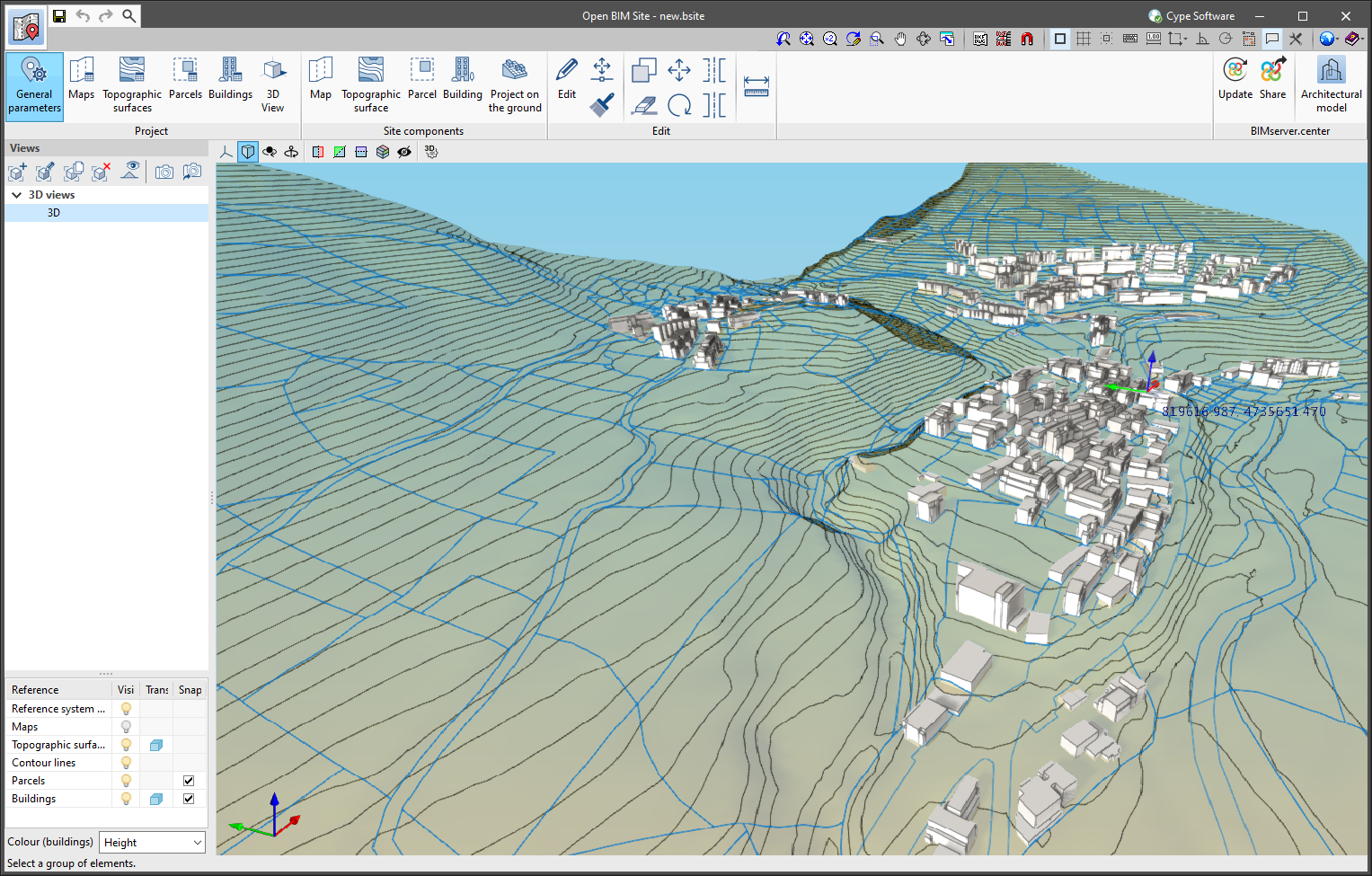
Open BIM Site
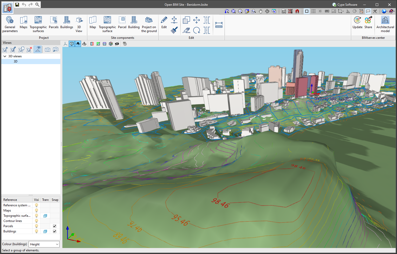
Contour lines
In the field of topography, contour lines are lines that connect points on a map with identical altitudes. Thanks to this technique, areas with different elevation differences can be easily identified.
The generation of contour lines in Open BIM Site is automatic. However, users can control their visualisation of the 3D model of the site using the application’s left-hand sidebar.
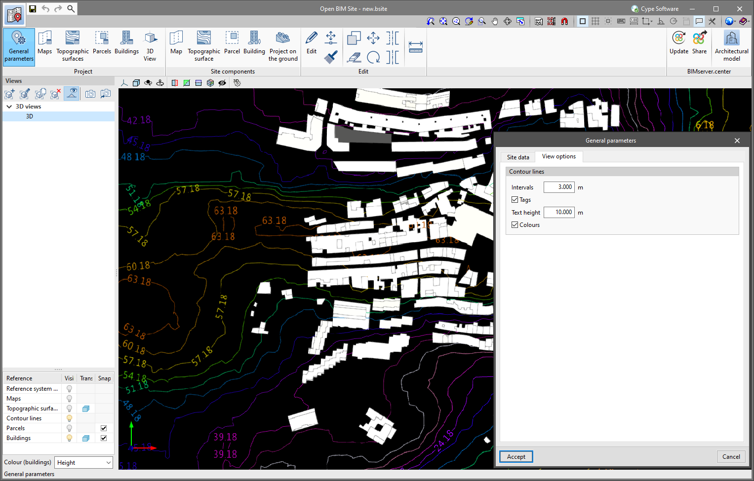
The "General parameters" panel, available in the application toolbar, has been divided into two tabs. The "Site data" tab contains the information related to the georeferencing of the model that was already present in previous versions of the tool. To configure the viewing of contour lines, the "View options" tab has been added with the following parameters:
- Intervals
Shows the vertical distance between two contour lines. - Tags
When activating this option, a text is displayed along with the contour lines to show their elevation.
- Text height
Determines the tags’ text size.
- Text height
- Colours
When this option is activated, a colour scale will be used to represent contour lines according to their elevation. Otherwise, the contour lines will be drawn in black.
Open BIM Analytical Model
Improved accuracy of the algorithm for automatically generating the analytical model
The algorithm for automatically generating the analytical model has been improved in the following ways:
- The process used to assign the properties of the walls and floor slabs in the physical model to the surfaces generated in the analytical model has been optimised.
- A problem in the process of detecting openings in the physical model (doors, windows, skylights, etc.) that could generate openings in analytical surfaces where this was not necessary has been corrected.
- An error caused by the generation of edges with a length of zero after the analysis of the surfaces of the analytical model has been corrected.
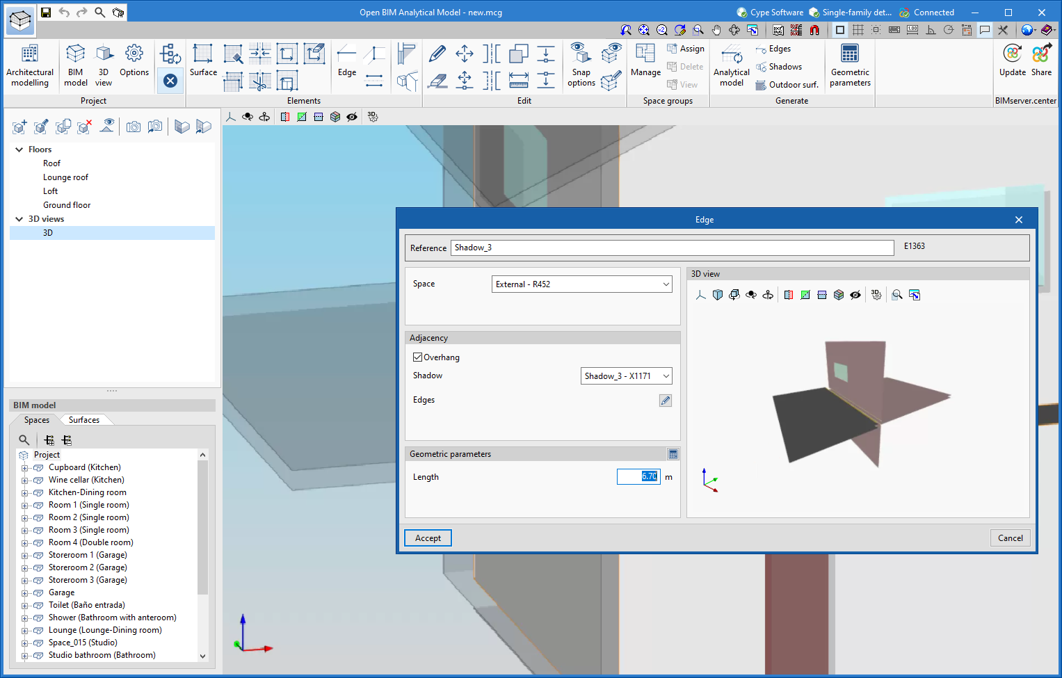
Defining overhang in connections between construction elements
As of version 2022.f, Open BIM Analytical Model allows edges originating from overhangs in the physical model, such as defences, to be introduced. To do this, the "Overhang" option has been added to the "Edge" configuration panel, in the "Adjacency" group.
CYPECAD and CYPE 3D
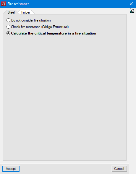
Critical temperature
As of version 2022.f, CYPECAD and CYPE 3D allow the critical temperature of steel sections to be obtained for fire situations. The value of the temperature that each section must reach for collapse to occur is calculated by means of an iterative procedure, taking into account the combinations established by the code selected for the fire situation as well as the mechanical properties of the steel at elevated temperatures.
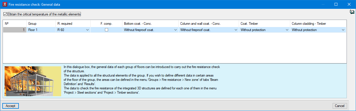
The results can be checked on screen, or in a summary table that includes the critical temperature and the shape factor corresponding to each of the structure’s sections. This facilitates the use of catalogues of manufacturers of intumescent paint in order to obtain the thickness necessary to ensure that the load bearing capacity of the structure is maintained for the time required by the applicable fire code.
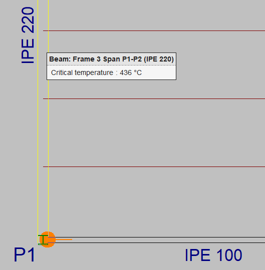
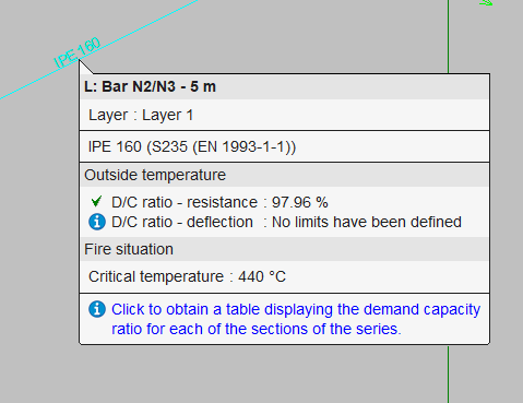
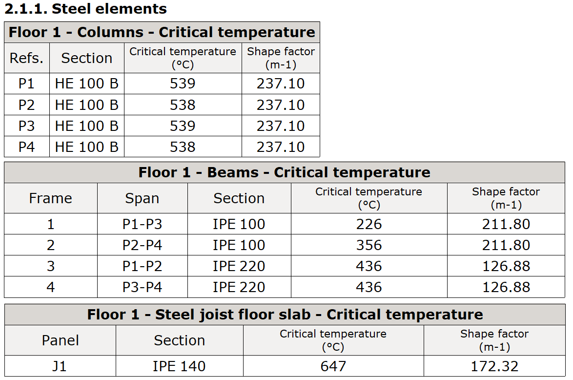
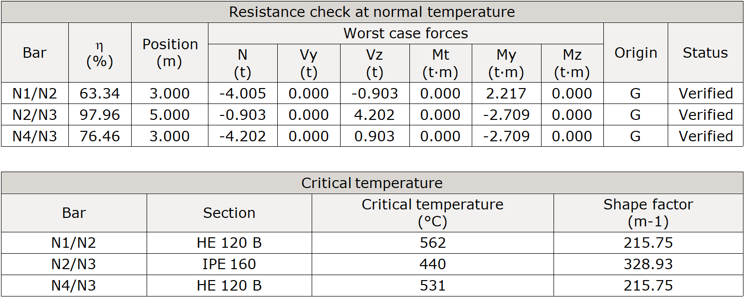
Since the critical temperature value of a section depends on the demand capacity ratio or demand factor of the section, this new feature is an excellent tool for optimising the total cost of the structure including its passive protection for the required fire resistance time.
CYPECAD
Downloading from the BIMserver.center platform
From 26 January 2022, the CYPECAD application is available for download from the BIMserver.center Store.
Therefore, CYPECAD can be installed by downloading the complete classic package from the download area of the CYPE website (11 GB) or by downloading CYPECAD (9.5 GB) from the BIMserver.center Store.
From this moment on, other applications from the classic CYPE package will be included in the BIMserver.centre Store for individual download.
The advantage of downloading from the BIMserver.center Store is not only that the individual downloads are more lightweight than the complete classic package, but also that it allows users to work with different versions of CYPECAD and other applications from the complete classic CYPE package.
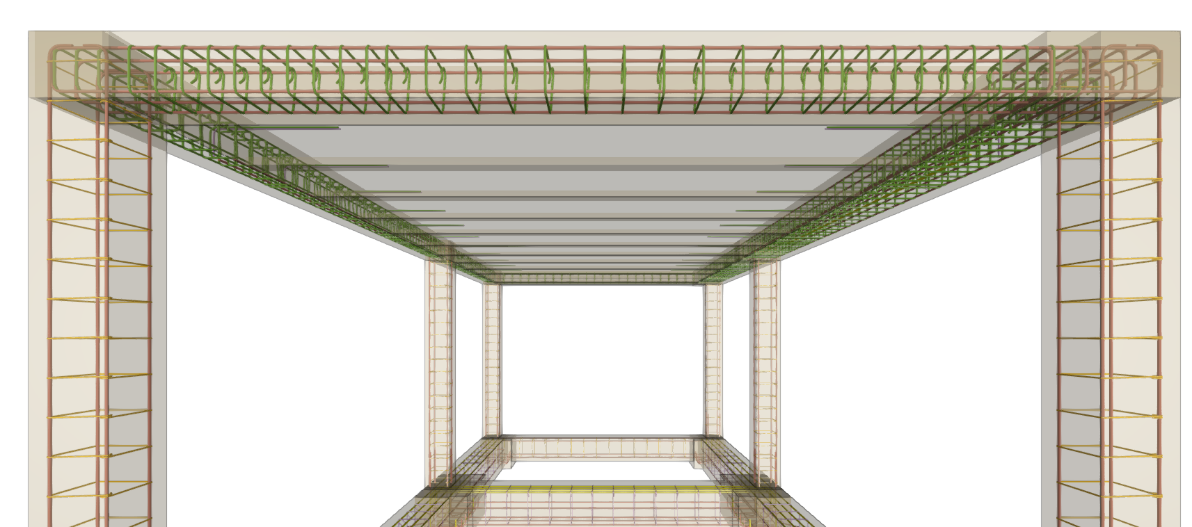
Exporting additional rebars of reinforced concrete beam frames to the BIM project
CYPECAD version 2022.f allows users to export additional rebars of reinforced concrete beam frames to the BIM project.
Therefore, the concrete elements that export their reinforcement to the BIM project up to this version are:
- Beam frames
- Columns
- Corbels
- Foundation elements
Footings, pile caps, strap beams and tie beams. - Floor slabs
Joist, waffle, hollow-core plate, composite, and flat floor slabs.
This reinforcement can be viewed, along with the reinforcement exported from StruBIM Shear Walls, in the StruBIM Rebar program.
They can also be viewed in the "Results" tab (Groups menu > 3D view with details).
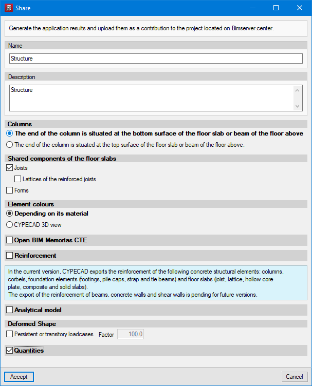
Exporting concrete quantities to the BIM model
After carrying out the complete analysis of the job, the information of the concrete volumes can be exported to the BIM project. To do this, the "Quantities" option has been implemented in the "Share" dialogue box that appears when the "Share" option is clicked in the "BIMserver.center" menu.
The export of concrete quantities to the BIM model can be imported and interpreted by other tools such as Open BIM Quantities.
In Open BIM Quantities, this data can be used for carrying out the bill of quantities of the concrete used in the project.
Processors used for the portal frame generator
The portal frame generator makes extensive use of all the available processors. This can significantly slow down the performance of other programs that are installed on the device while the program is designing the frames. In order to avoid this, an option has been added (Project menu > General options) that allows users to establish the number of processors that the program will not use while it is designing the frames.
Other improvements and corrections
Version 2022.f of CYPECAD includes other minor improvements and corrections of the program for certain cases:
- Foundation
An error that occurred when analysing jobs containing foundation elements with soil-structure interaction in floors affected by wind loads has been fixed. - Non-structural beams
Non-structural beams or limit beams are allowed at the ends of timber joists. - Columns schedule
An error that occurred when obtaining the columns schedule of jobs containing a code without ULS checks, and that had a special character in the job name (an exclamation mark, for example) has been fixed. This error occurred in the changes made in version 2022.e. - Columns schedule
An error that occurred when obtaining the column schedule in some unique cases involving sloping roofs has been fixed. - Concrete code selection
There is an improvement in the organisation of concrete codes when it comes to selecting them. - Foundation beam dimensioning
The dimensioning of foundation beams in walls in the drawing of frames has been improved. In some cases, the length shown was somewhat longer than the actual length. - Jobs with shear walls and deleted temporary files
An error that occurred when a job with shear walls was opened and its temporary files were deleted after it had been analysed, has been fixed. - Sharing with BIMserver.center with the Spanish structural code "Código Estructural" as the selected standard
In the "Share" dialogue box (BIMserver.center menu > Share) users can select the "Open BIM Memorias CTE" option if the selected standards are those corresponding to the Spanish structural code "Código Estructural".
CYPE 3D
Units of the stress scale in contour plots
In contour plots, the values of the stress scale are displayed in kp/cm2 for the MKS system.
CYPE Connect and StruBIM Steel
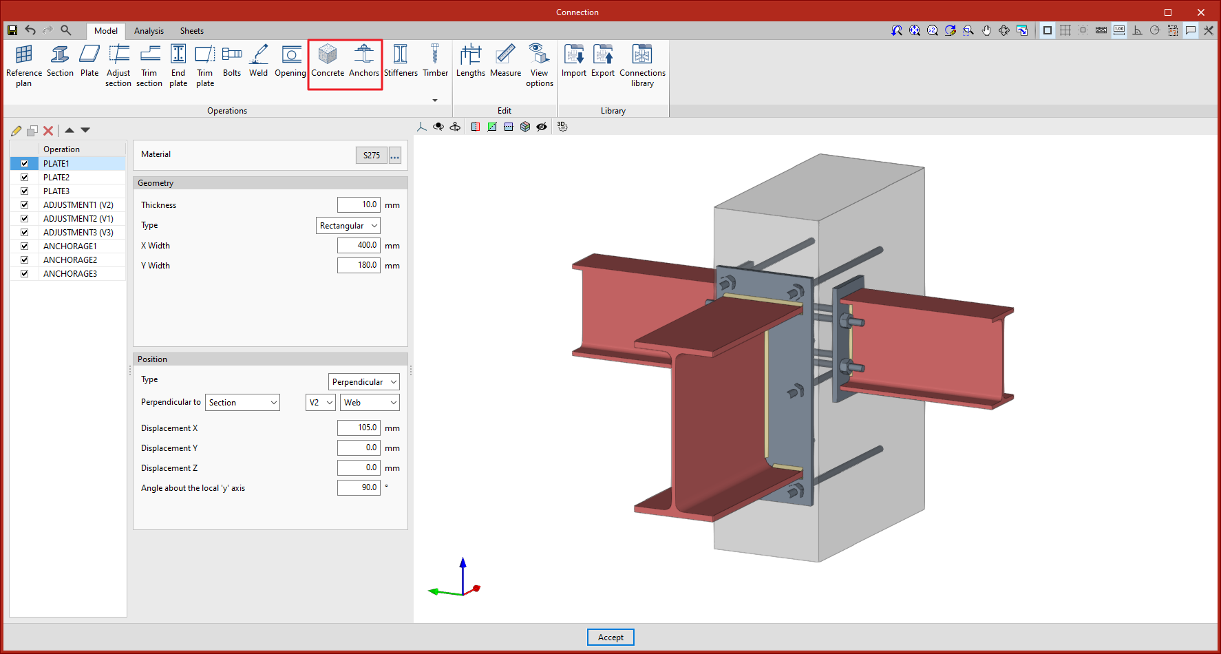
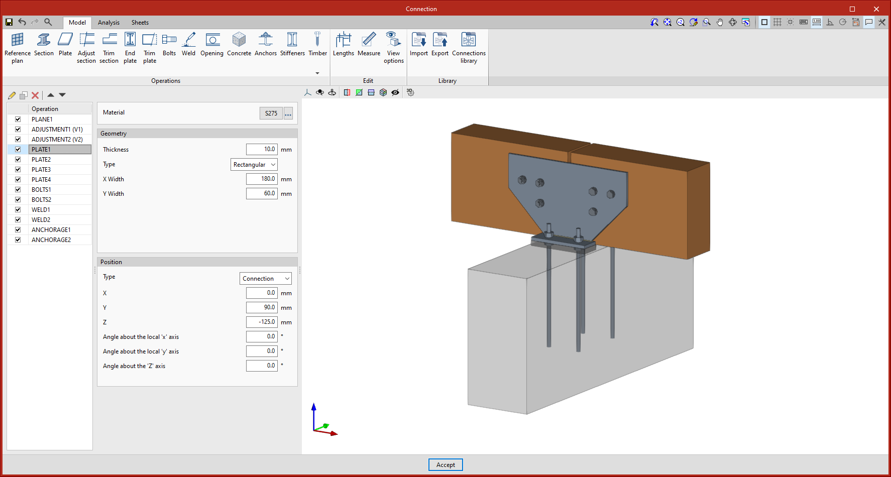
Concrete anchors
As of version 2022.f of CYPE Connect and StruBIM Steel, users can now model and design elements anchored to concrete. To do this, the "Anchors" and "Concrete" features have been included for modelling the connection.
- Anchors
The "Anchors" feature allows users to introduce the anchor elements of a steel plate or section into a concrete block. The program allows users to design the connection given the geometrical layout of the fastenings, as well as their geometrical and mechanical properties. There is a choice of different types of anchors, either welded or bolted.
The anchorage can be made either to a new concrete block defined in the operation itself or to an existing block that has been previously defined.
- Concrete
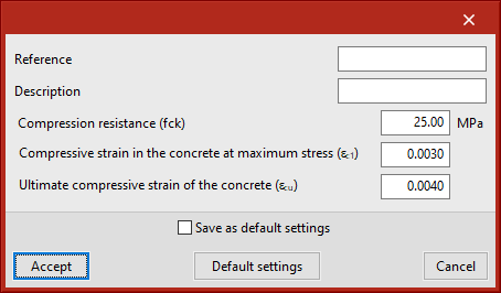
The "Concrete" feature allows users to enter a concrete block where the material, dimensions and position of the block are defined.
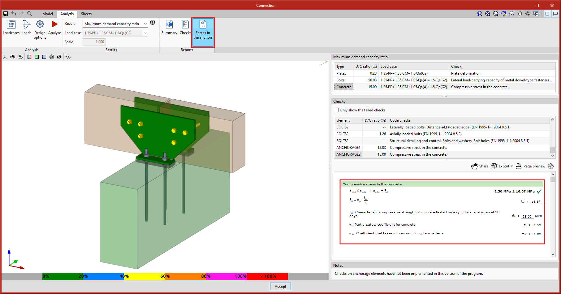
- Analysis
When the analysis is carried out, a finite element model is automatically generated that characterises the behaviour of the different components involved in the connection, considering the type of anchors and the properties of the concrete block. Once the analysis has been completed, the compressive strengths in the concrete can be checked. The anchors cannot yet be checked in version 2022.f, but their resulting forces can be consulted.
CYPE Connect
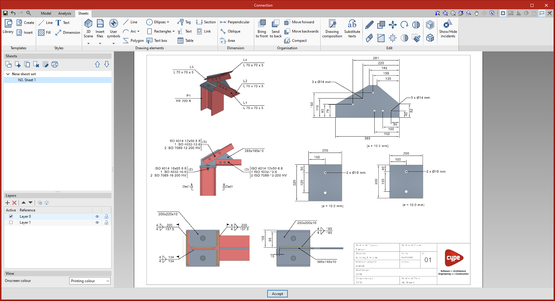
Connection drawings
As of version 2022.f, CYPE Connect includes a new tool to help users create detail drawings for connections by integrating the editing and composition features from Open BIM Layout.
Once a connection has been modelled, users can switch to the sheet tab, where they can find the tools available for creating the details.
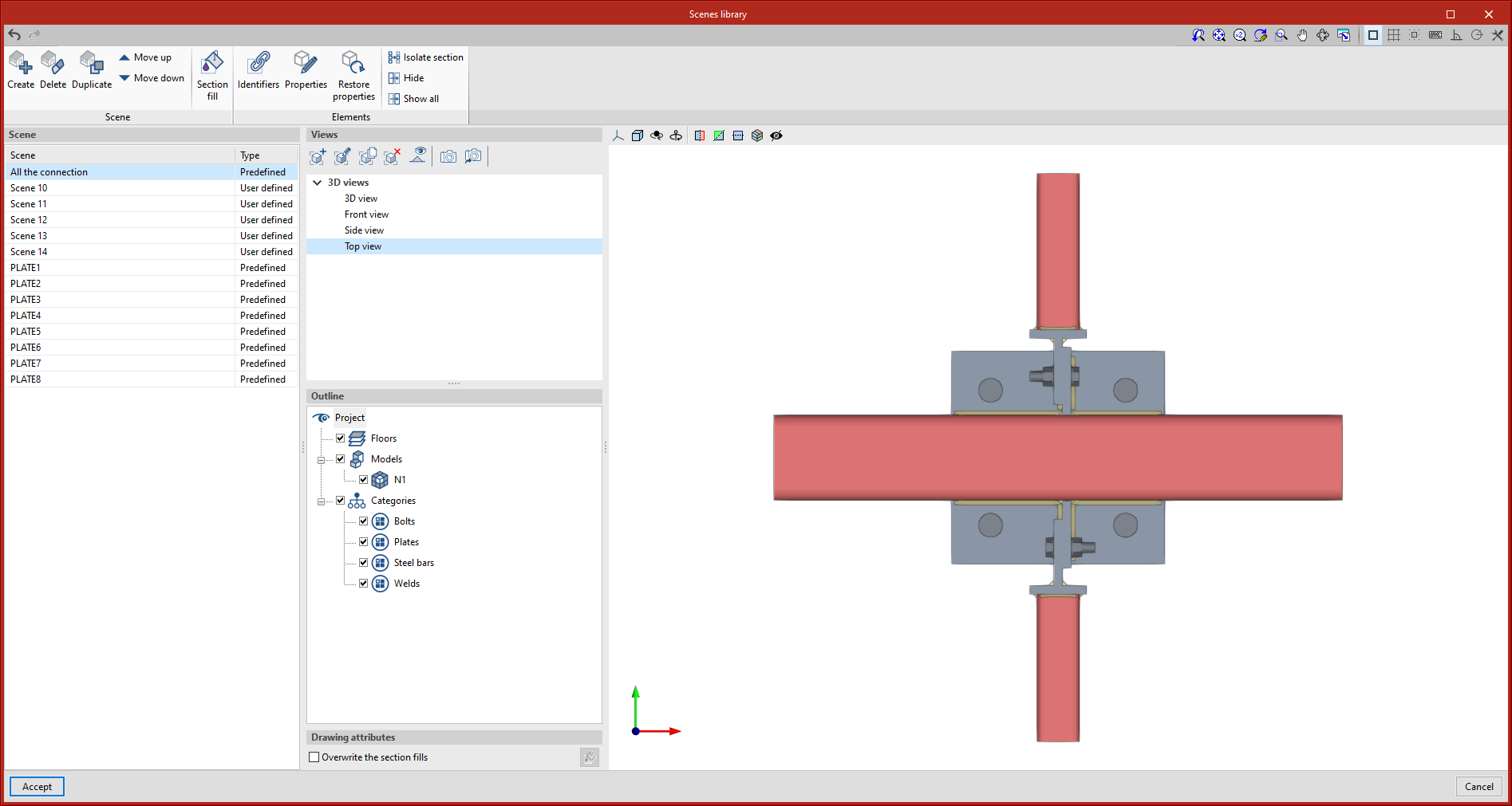
- Scenes and Views
To create the sheets, views of the connection model (front view, top view, side view, 3D view, etc.) can be inserted at the desired scale.
The program allows predefined views to be inserted, but user-defined views can also be created and inserted.
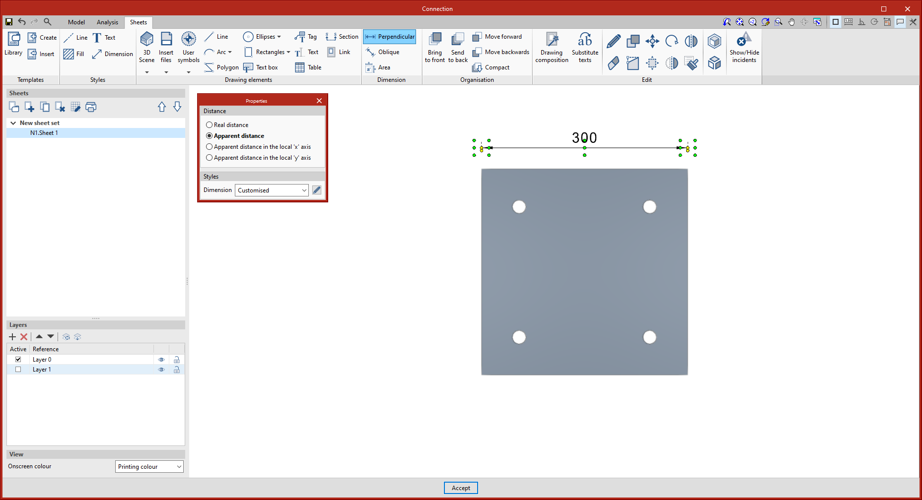
- Dimensioning and Tagging
The program includes traditional drawing elements and dimensioning tools. Users can define and save their line, text or dimension styles to use them for any future sheets in connections.
When dimensioning the connection elements, once the elevation has been entered, both the auxiliary lines and the text position can be modified.
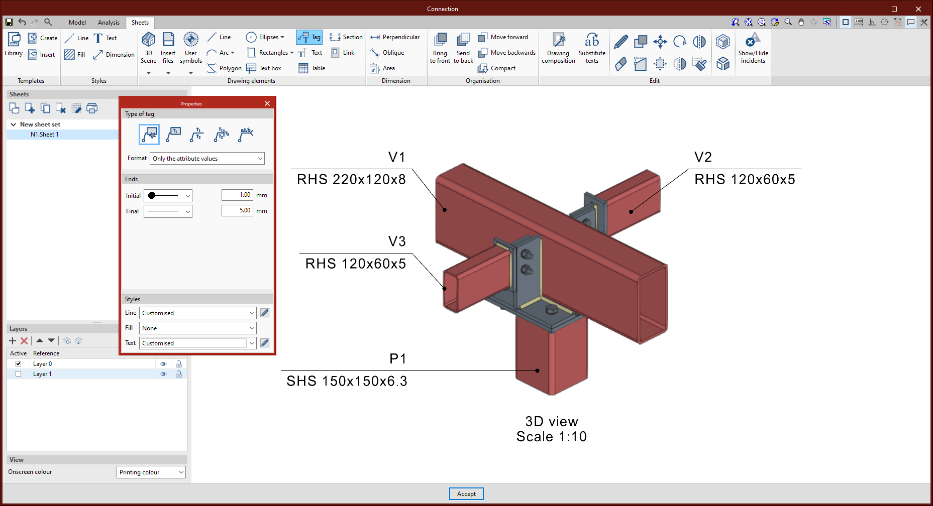
To tag elements, the tagging tool incorporates the most common types of tags in connection drawings. However, to speed up the process, the automatic tagging tool has been developed, which allows the selected element’s tag to be automatically generated with the content and shape predefined by CYPE Connect.
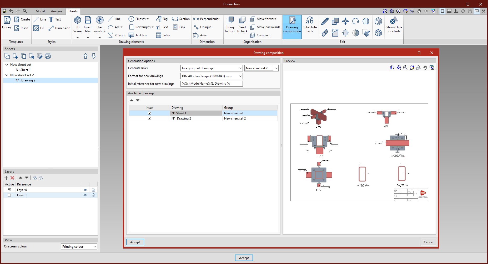
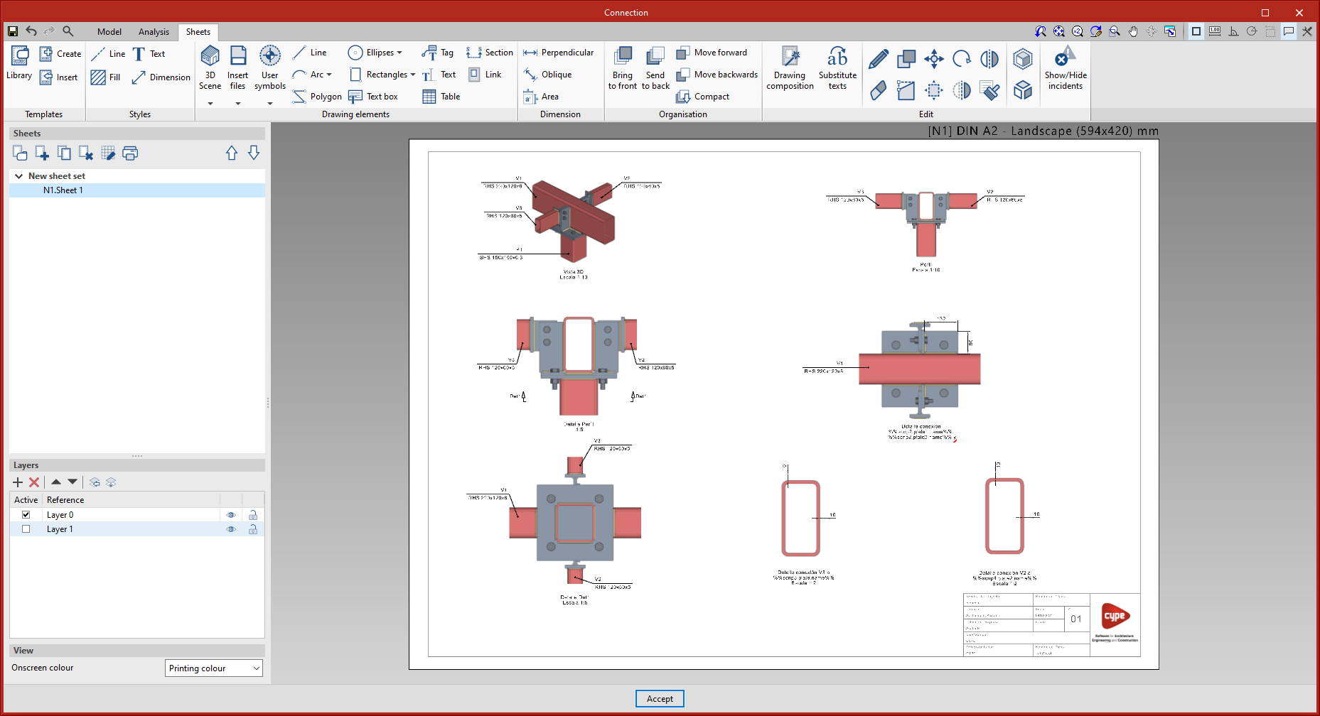
- Composition of sheets
Once the sheets have been detailed, the next step is the composition level, where one or more sheets can be created using the content of the other sheets.
The ‘Link’ tool allows users to add a reference to the content of one sheet to another, while the ‘Composition of sheets’ tool generates a mosaic of the selected sheets.
- Linking with the connection model
The content of the sheets is linked to the model of the connection, i.e. the scenes and views that have been defined, as well as the element tags entered, will be automatically updated if there are changes in the modelling of the connection.
CYPELEC Electrical Mechanisms
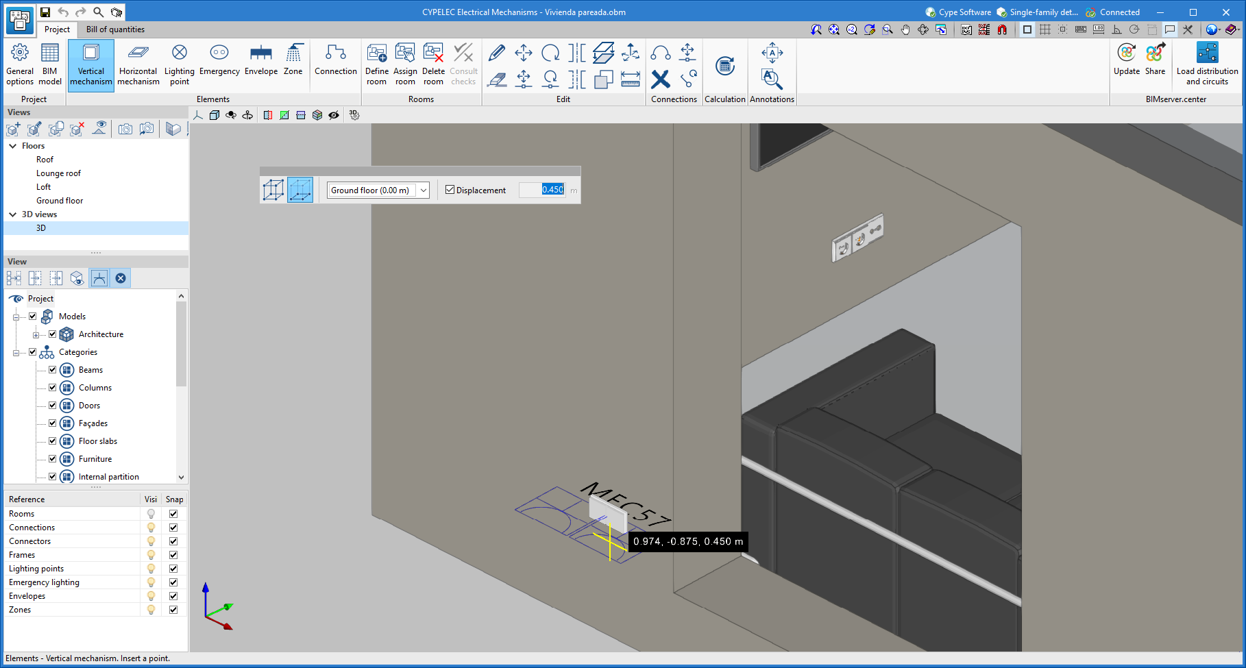
Automatic orientation when introducing mechanisms
When a mechanism is inserted on a vertical plane, the program snaps the plane of the element on which it is to be positioned and the mechanism is automatically oriented.
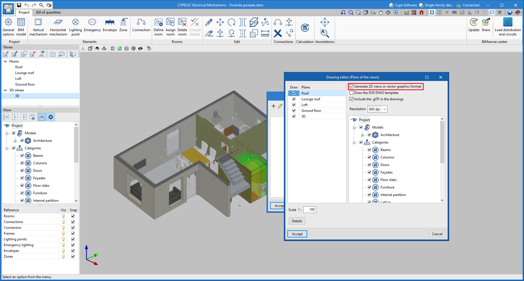
2D drawings in vector graphics format
When elaborating electrical drawings, an option has been added that allows users to create drawings of the 2D views in vector graphics format. These drawings can be generated in DXF and DWG file formats.
Generating and assigning electrical outlets for equipment imported from the BIM model
A new feature is added to the program that allows users to both manually and automatically assign outlets to the equipment imported from the BIM model.
When reading a BIM project, CYPELEC Electrical Mechanisms allows electrical equipment included in the architectural model to be imported, such as: televisions, cookers, washing machines, dishwashers, extractor fans, refrigerators, microwaves and computers.
The program will notify users when the required service needs to be provided for this equipment. This service can be carried out by means of a manual or automatic assignment of the previously introduced required outlet, or by means of an automatic generation of outlets, according to the criteria for the selection of outlets per appliance.
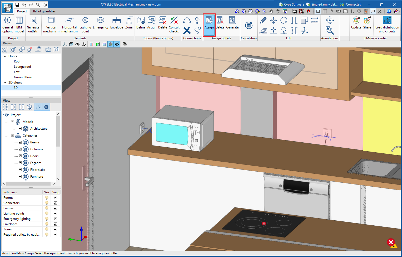
- Manual assignment with previously introduced outlets
In order to carry out this manual assignment, users must click on the "Assign" button in the "Assign outlets" group in the toolbar and in this order. First, the equipment is chosen, and then the outlet to be assigned.
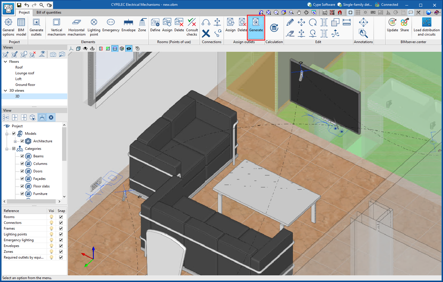
- Automatic assignment with previously introduced outlets
In order to carry out this automatic assignment, users must click on the "Generate" icon in the "Assign outlets" group in the toolbar. The program will select the one that is best suited for service and proximity from those available.
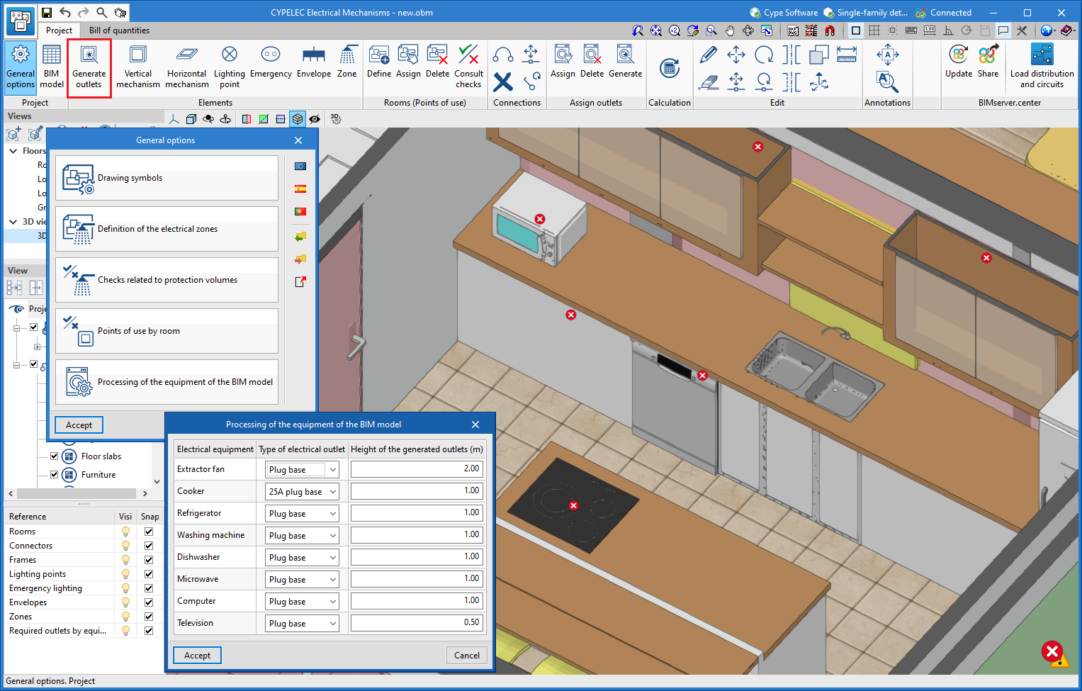
- Automatic generation of outlets per equipment
In order to carry out this automatic generation, users must click on the "Generate outlets" icon in the "Elements" group in the toolbar. The program will introduce the outlets required depending on the service required for each device. The criteria for their introduction depends on the selection made in the "Processing of the equipment of the BIM model" section of the general options.
CYPELEC Distribution
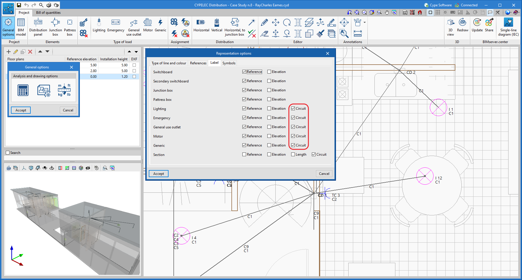
Designating supply circuits in the receivers
Now users can indicate the reference of the circuit that supplies power to the different receivers (lighting, emergency, general use outlets, motor and generic load).
CYPELEC PV Systems
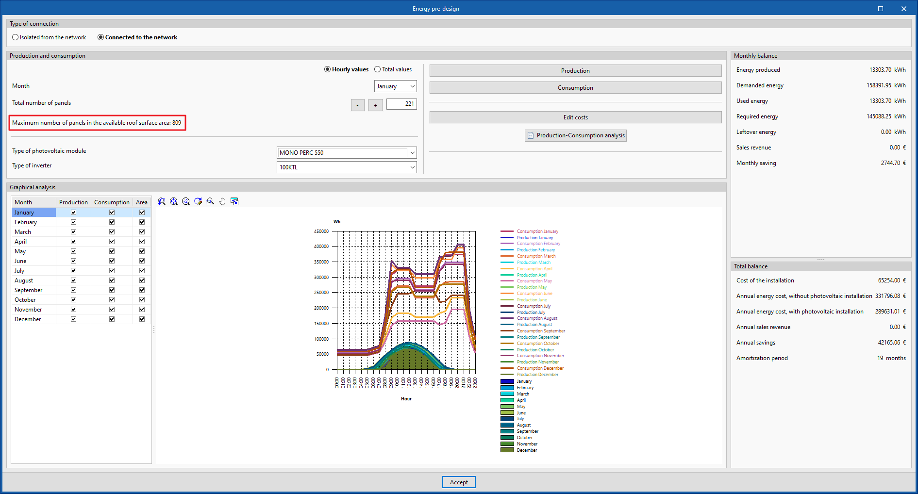
Maximum number of panels in the available roof surface area
If the architectural model of the associated BIM project has been imported, the CYPELEC PV Systems energy pre-design analyses and displays the maximum number of panels in the available roof surface area.
Automatically adapting panels into roofs using overlay or architectural integration
If the architectural model of the associated BIM project has been imported, when solar panels of the "Overlay" or "Architectural integration" installation types are inserted, moved or copied, CYPELEC PV Systems automatically detects the roof and its inclination and places the panel on it with its corresponding inclination.
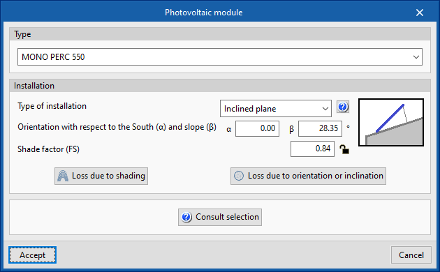
Editable shade factor for each panel
CYPELEC PV Systems version 2022.f allows the shade factor to be set manually. To do this, the shade factor (SF) is incorporated as a parameter in the "Photovoltaic module" editing panel with a padlock that allows the value to be locked. Thus, if the padlock is open, the software analyses the shading diagram of the panel and obtains the shade factor value. On the other hand, if the shade factor is entered manually and then locked (the padlock is closed), the software will not analyse the shading diagram, and its shade factor will be defined by the manually entered value.
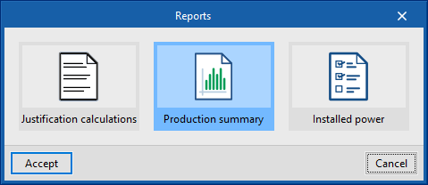
"Production summary" document
Version 2022.f of CYPELEC PV Systems generates a production document as a summary. It shows the production values for each period as well as a bar chart showing all of them together.
Optimisation of the shading analysis process
Version 2022.f of CYPELEC PV Systems includes an optimised shadow analysis process, which reduces calculation time.
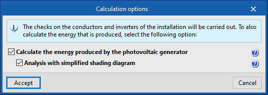
Option for calculating the energy produced using simplified shading diagram
When calculating the energy produced by the system, CYPELEC PV Systems version 2022.f enables an option to obtain the shading diagram of the panels in a simplified way. With this option, the program extends the intervals with which the shading diagram is analysed.
CYPETEL Schematics and CYPETEL Systems
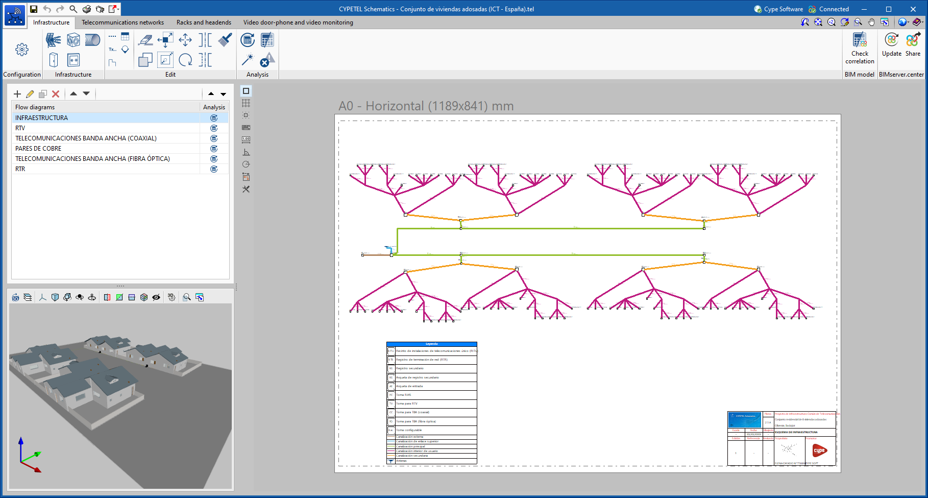
New example job
A new example job (Conjunto de viviendas adosadas) has been included that allows users to see the capacities of the programs in the design of plans and diagrams in ICT projects of terraced houses.
CYPELUX, CYPELUX EN and CYPELUX LEED
Only available on the BIMserver.center platform
As of version 2022.f, the CYPELUX, CYPELUX EN and CYPELUX LEED applications will be available exclusively on the BIMserver.center platform. Therefore, they will not be installed with the classic software package downloaded from the CYPE website.
CYPEHVAC Hydronics
Connection with Open BIM Database
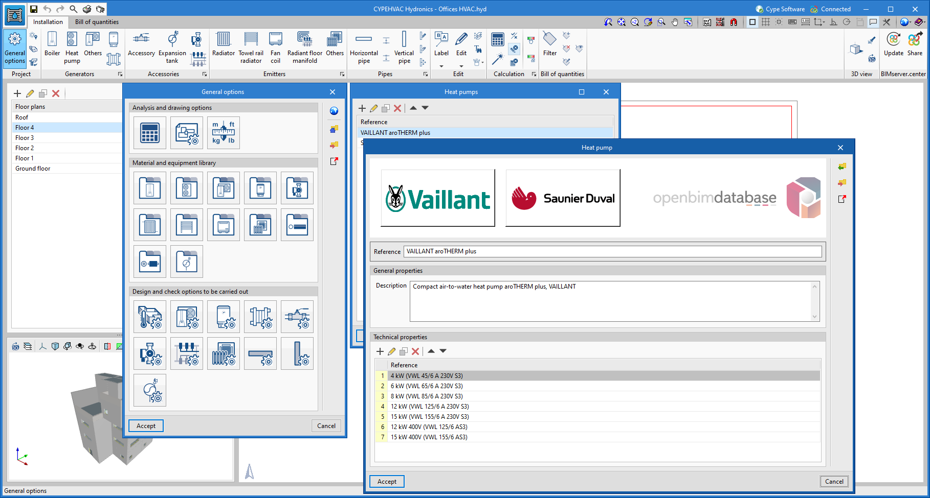
CYPEHVAC Hydronics connects to Open BIM Database, from where it downloads the manufacturers’ products in order to incorporate them into the design of the water HVAC system.
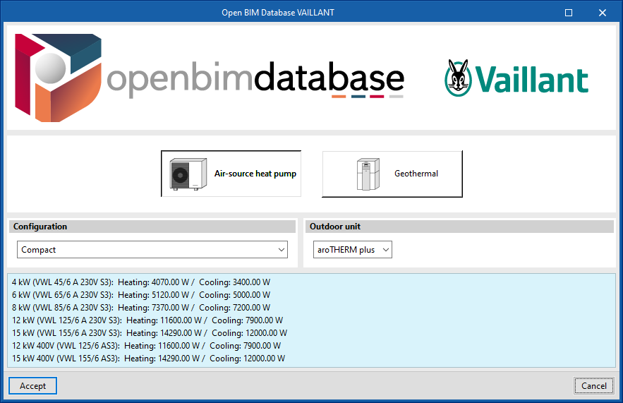
In version 2022.f, users can now download manufacturer data for heat pumps and fan coils from Open BIM Database to the respective libraries of the program. To do this, under "General options", users must enter the library folder of one of the two units and click on the add button. In the following window, by clicking on the manufacturers’ logos, the catalogue of the chosen type of unit can be downloaded.
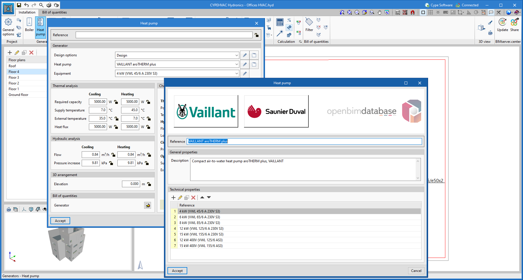
Similarly, these library editing and downloading panels can be accessed from the new buttons at the top of the Heat Pump and Fan coil editing panels.
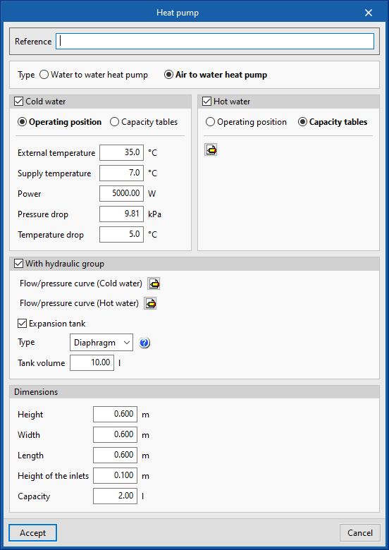
In order to consider more analysis data for heat pumps and fan coils provided by manufacturers, new design variables have been added for both types of units. One of them is the option of defining their capacity tables, which is added as an alternative to the definition of a nominal operating point. In this way, when changing the system’s design conditions, the program analyses the power offered by the units again and checks that the operating position is within the indicated operating range.
Heat pumps have been divided into two types, air-to-water and water-to-water. The air-to-water heat pumps collect the outdoor temperature data from the selected site. Additionally, users can now also define a hydraulic group associated with the heat pump that includes a circulating pump and, optionally, an expansion tank.
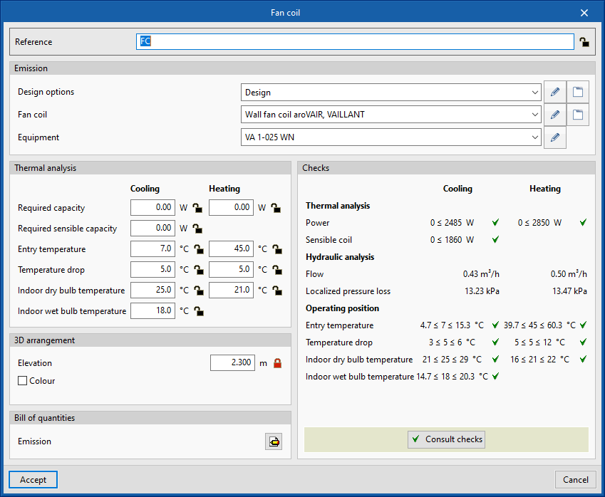
For fan coils, the cooling design indoor wet bulb temperature has been added, which is automatically calculated from the relative humidity and indoor temperature conditions of the space where the unit has been installed.
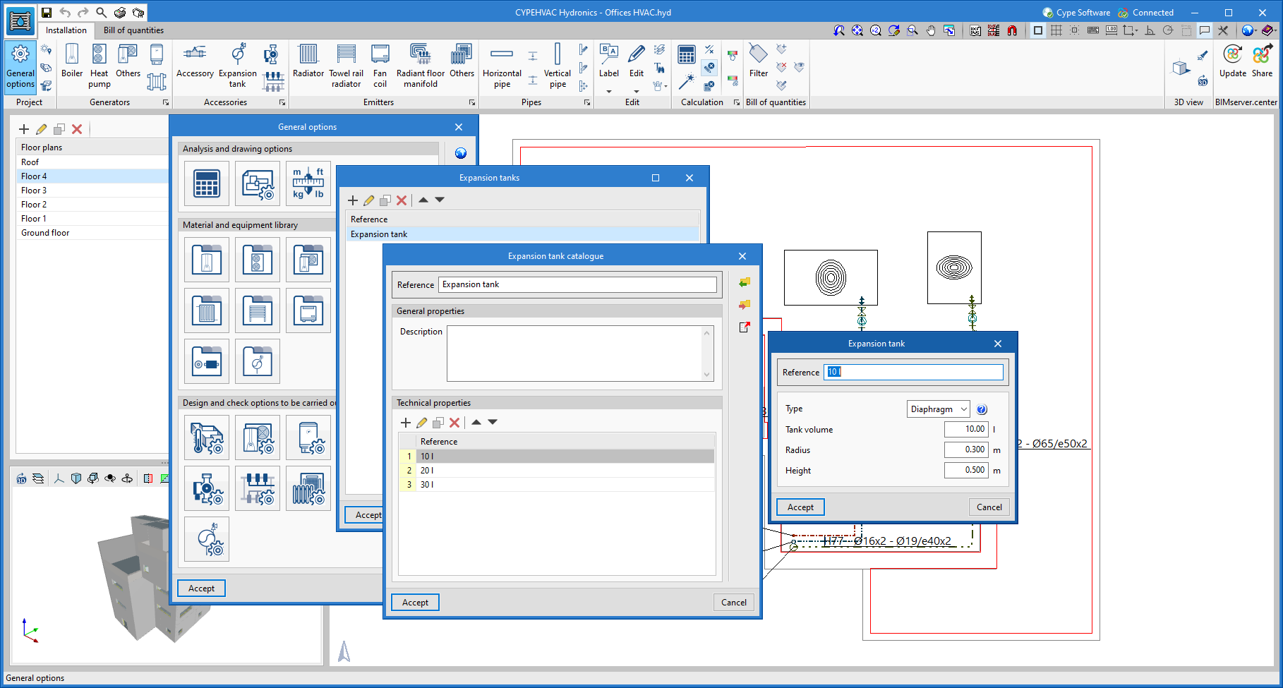
Designing the expansion tank
CYPEHVAC Hydronics is now able to design a new element of the water HVAC system: the expansion tank.
Just like the other elements in the system, in order to use an expansion tank, users must first define its properties in the expansion tank library.
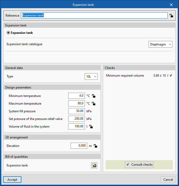
From the Expansion tank button in the toolbar, users can select the defined expansion tank, define its design data and place it on the drawing of the system. By clicking on the Calculate button, the program collects the minimum and maximum temperature and volume of fluid in the system from the system associated with it and provides a check of the minimum required volume of the expansion tank according to its type.
It is also possible to define the expansion tank associated with the hydraulic group of a heat pump. The same type of calculations and checks will be carried out within the heat pump editing window.
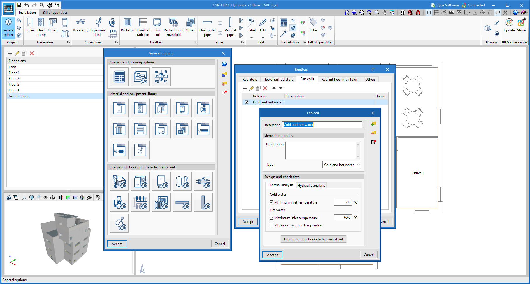
Maximum and minimum inlet temperature limits of the water entering the emitters
Users can now check the maximum and minimum inlet temperature of the water entering the heating and cooling emitters, respectively. The limit to be checked can be configured in General options > Design options and checks to be carried out on the Emitters.
By default, a maximum inlet temperature of 60ºC and a minimum inlet temperature of 7ºC have been defined, which both coincide with the limits set by the Spanish thermal standard RITE.
CYPETHERM EPlus
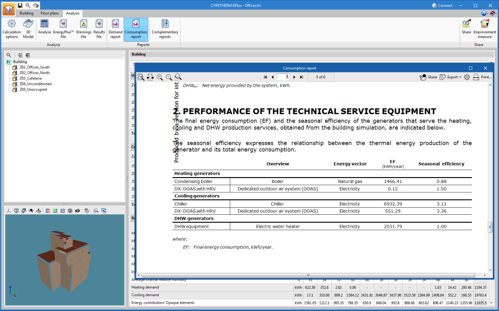
Consumption results for each unit
The Consumption Report has been expanded with a new section that lists the HVAC and DHW units defined in the building and indicates the energy consumption and seasonal efficiency for each of them.
Arquimedes
Bills of quantities of Revit models
Bill of quantities simulation with assigned items
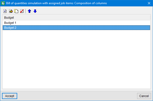
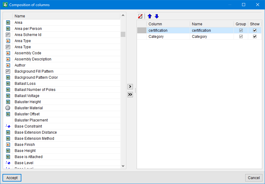
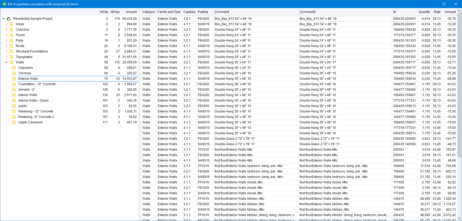
The "Bill of quantities simulation with assigned items" tool ( option button in the "Assign items and quantity extraction" window) has been implemented. With this, it is possible to have several bill of quantities configurations to, for instance, carry out an analysis of partial bills of quantities. Each bill of quantities configuration can use any parameter of the job and property customised by the user. These parameters act as work sections levels for creating the bill of quantities.
This way, the main bill of quantities in Arquimedes can be divided depending on the values of a parameter or a custom feature. For example, the cost estimations of the different phases of a project or groups of projects can be obtained.
The "Bill of quantities simulation with assigned items" tool only works with items assigned to Revit entities.
The contents of the "Bill of quantities simulation with assigned items" window can be copied and pasted into a spreadsheet. To copy it, right-click on the column header and choose the corresponding option.
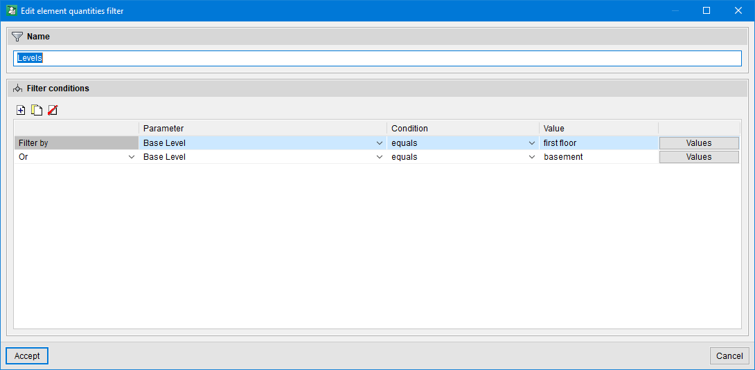
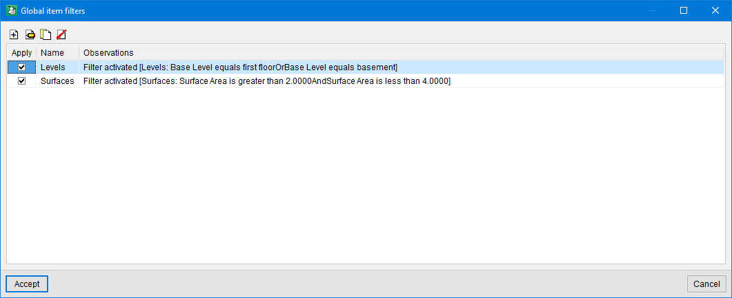
Global elements filters
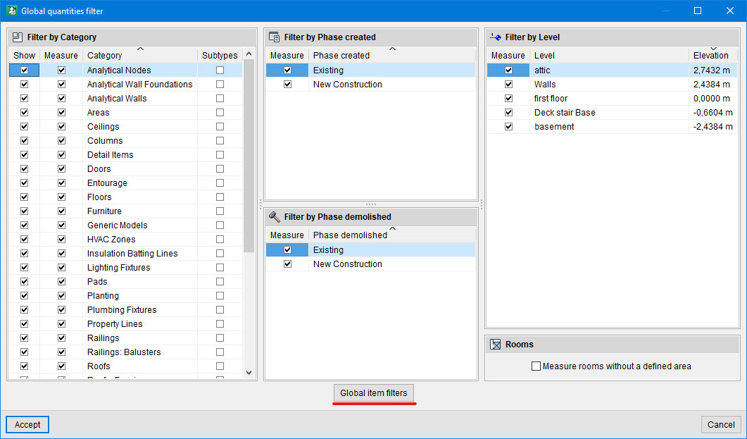
The "Global elements filters" option ( button in the "Assign items and quantity extraction" window > "Global quantities filter" > "Global elements filters" button) has been added. Using it, users can filter out elements that they wish to measure and that meet certain conditions. In this way, a partial cost estimation can be obtained with only the filtered quantity lines.
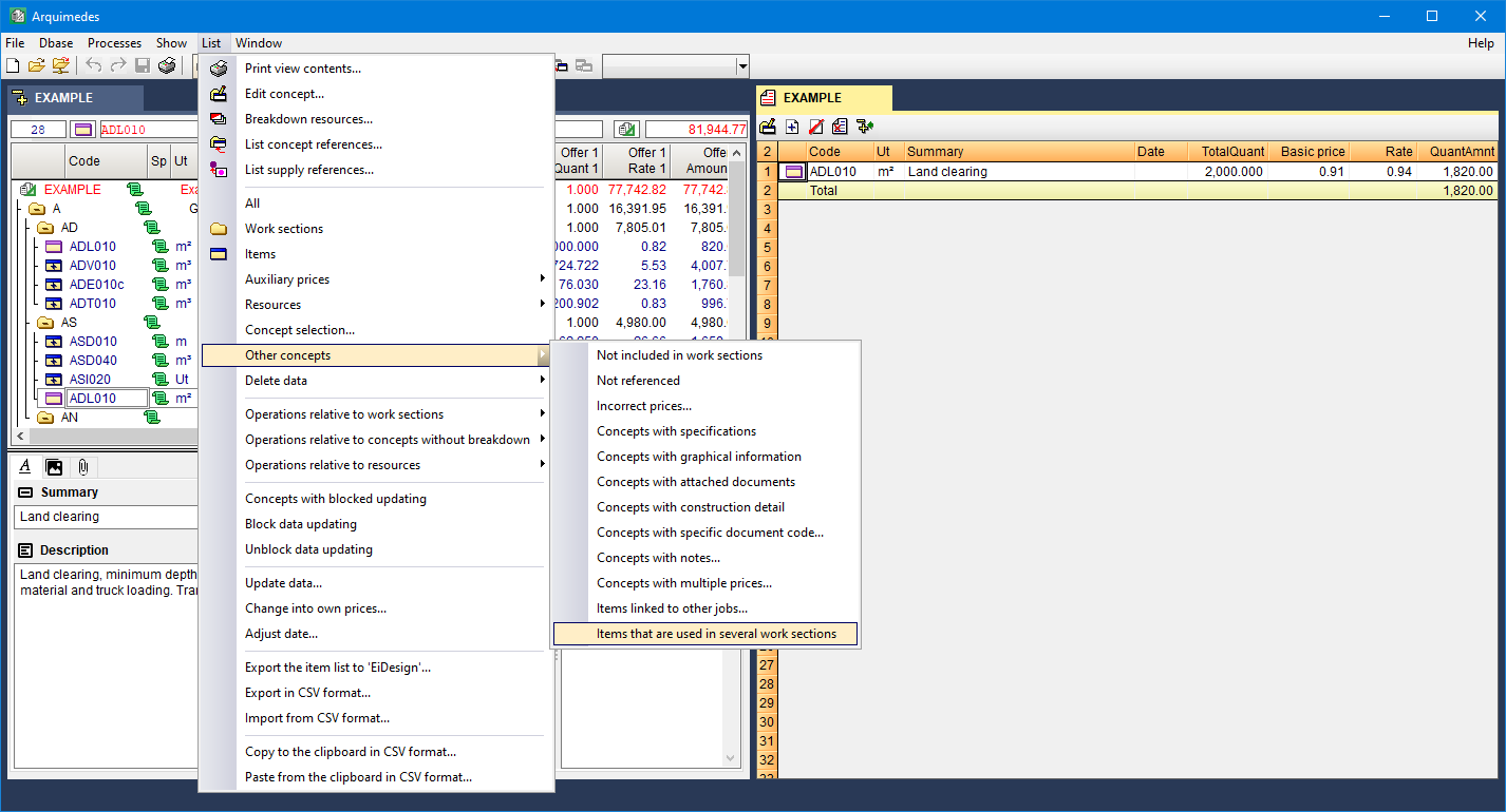
Items that are used in several work sections
The "Items that are used in several work sections" option ("List" menu > "Other concepts" > "Items that are used in several work sections") has been added. This option allows users to identify items that are used in more than one work section. Furthermore, the item is identified by the  icon.
icon.
Open BIM Quantities
New options in the "Update the quantities" panel
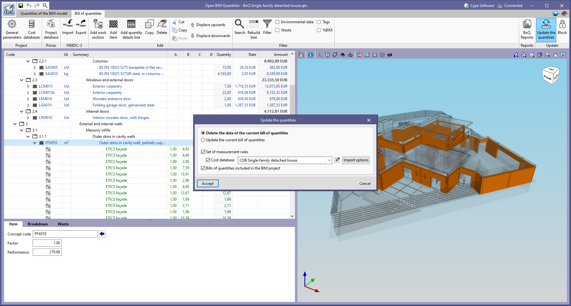
The "Update the quantities" window displayed when selecting the "Update the quantities" tool in the "Bill of quantities" tab has been modified. The following options have been added:
- Set of measurement rules
Checking this option will apply the set of measurement rules that are active in the IFC files, originating from the BIMserver.center project contributions, that have been uploaded to Open BIM Quantities. - Bills of quantities included in the BIM project
Checking this option will add the bills of quantities from the BIMserver.centre project contributions that have been selected via the "Bills of quantities included in the BIM project" option from the toolbar in the "Quantities of the BIM model" tab.
Reading the model reference and the source application of the IFC entities
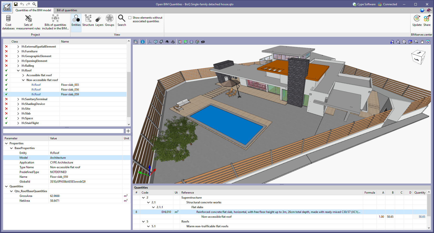
Each application involved in a BIM project on the BIMserver.centre platform includes a BIM model in this project by means of an IFC file that consists of different entities. Open BIM Quantities imports these entities with their corresponding properties.
As of version 2022.f, Open BIM Quantities displays two more properties for each entity imported from the BIM project: the reference of the BIM model from which it originates and the application from which it was generated. The model reference and the name of the source application are included respectively in the new "Model" and "Application" fields, which are in turn incorporated into the "BaseProperties" property set. Just like the other properties and quantities, this data can be used in the rules of measurement as part of the selection of elements of the project or to type in the commentary of the detail lines of an item. It is also possible to use them in the "Filter" tool to display, for example, the bill of quantities of a specific contribution.
In order to view the new properties in jobs carried out with previous versions of Open BIM Quantities, users must update the BIMserver.center project in the application again.
User's manual
The Open BIM Quantities user’s manual has been available in Spanish since the previous version (2022.e). Now, in version 2022.f, the manual is available in the following languages:
- Spanish (available since version 2022.e)
- English (available as of version 2022.f)
- French (available as of version 2022.f)
- Portuguese (available as of version 2022.f)
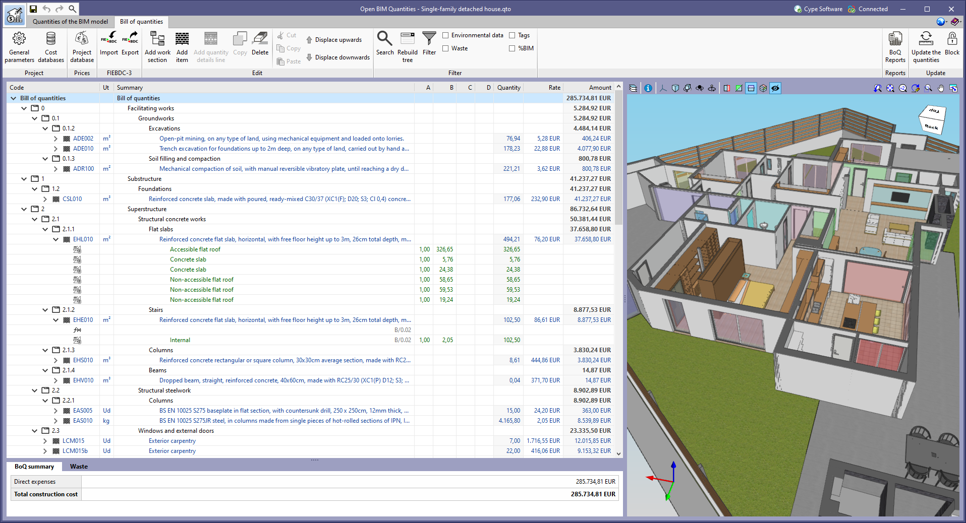
New example job
The example job "English – Single-family detached house" has been added together with its cost database and set of measurement rules ("English – Single-family detached house"). Both the architectural model, from the CYPE Architecture application, and the bill of quantities of the job have been created in English.
Return to the 2022 version download area
Tel. USA (+1) 202 569 8902 // UK (+44) 20 3608 1448 // Spain (+34) 965 922 550 - Fax (+34) 965 124 950