NEW FEATURES OF EXISTING PROGRAMS
NEW FEATURES OF EXISTING PROGRAMS
New features common to several programs
Programs included in the Open BIM workflow
BIMserver.center project status
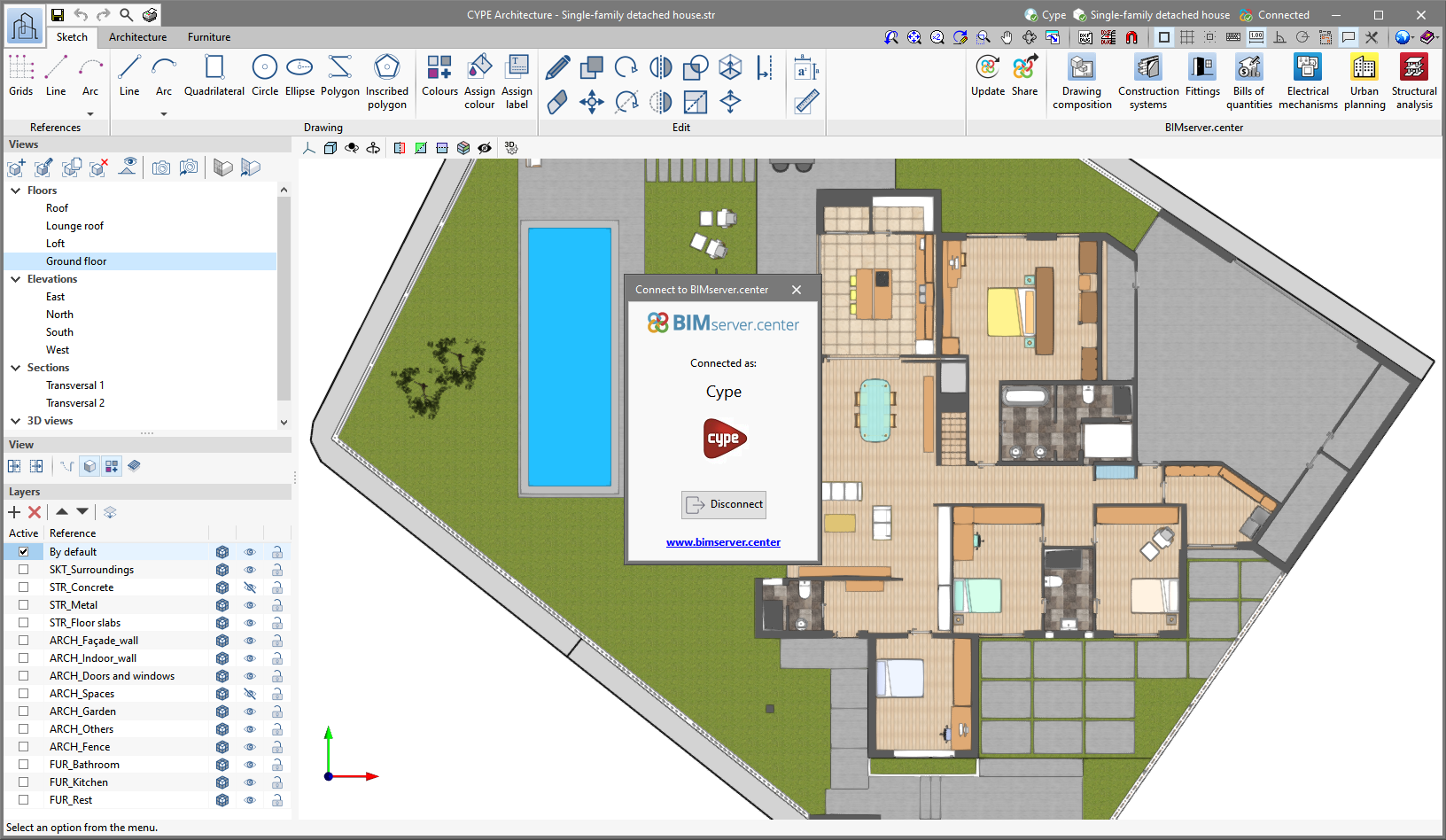
As of version 2022.e, the applications connected to BIMserver.center have an information bar displaying the link status to the project on the platform. This bar can be found at the top right of the application window and is divided into the following sections:
- User
Displays the BIMserver.center user name that has been entered to access the application. If a connection has not been established with a platform user, the text "Connect" will appear. If the user clicks on this button, they will be able to type in their name and password, as well as sign out in order to access with other login credentials.
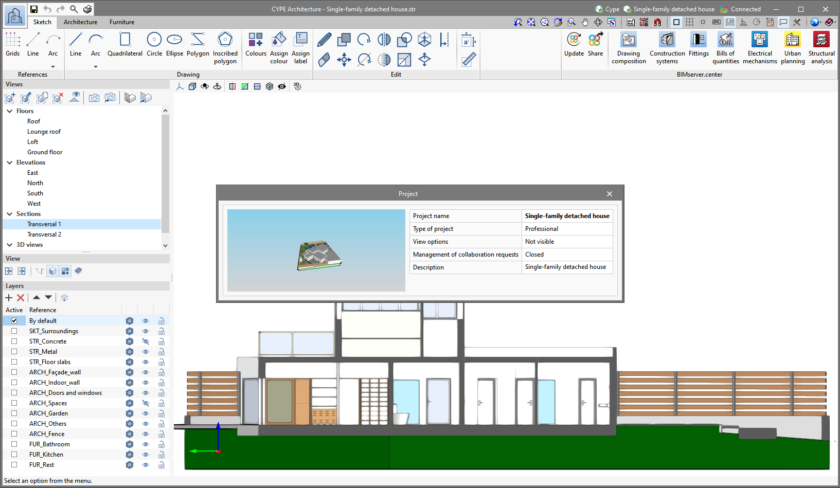
- Project
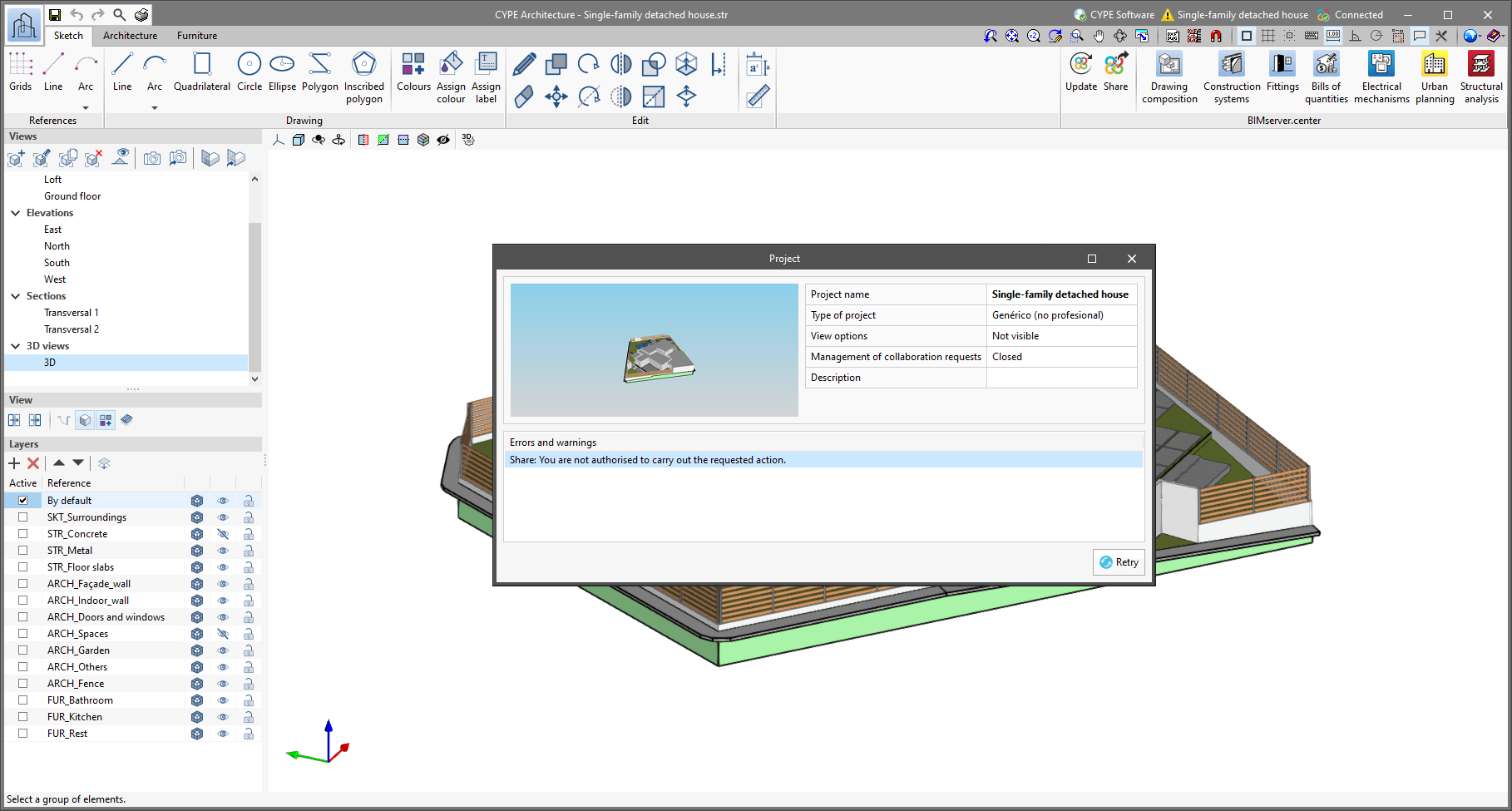
Displays the name of the BIMserver.center project linked to the job, if such a link exists. By clicking on this button, we can obtain additional information about the project, such as its description, project type or view options. If any warnings or errors occur when uploading or downloading contributions to the project, a list will be displayed in this panel with all the incidents detected. Furthermore, the project icon in the bar will change to a warning symbol.
- Status

Displays the status of the connection with BIMserver.center.


When a contribution is being uploaded or downloaded, the text of the message changes and the progress of the action is displayed.
If an older version of the BIMserver.center Sync synchronisation tool is running, the message "Incompatible version of the BIMserver.center synchroniser" is displayed.

The synchroniser can be downloaded and installed free of charge from the BIMserver.center platform or installed during the installation process of the applications. The latest version of the tool is required for applications to be able to display status messages.
Linking to BIMserver.center
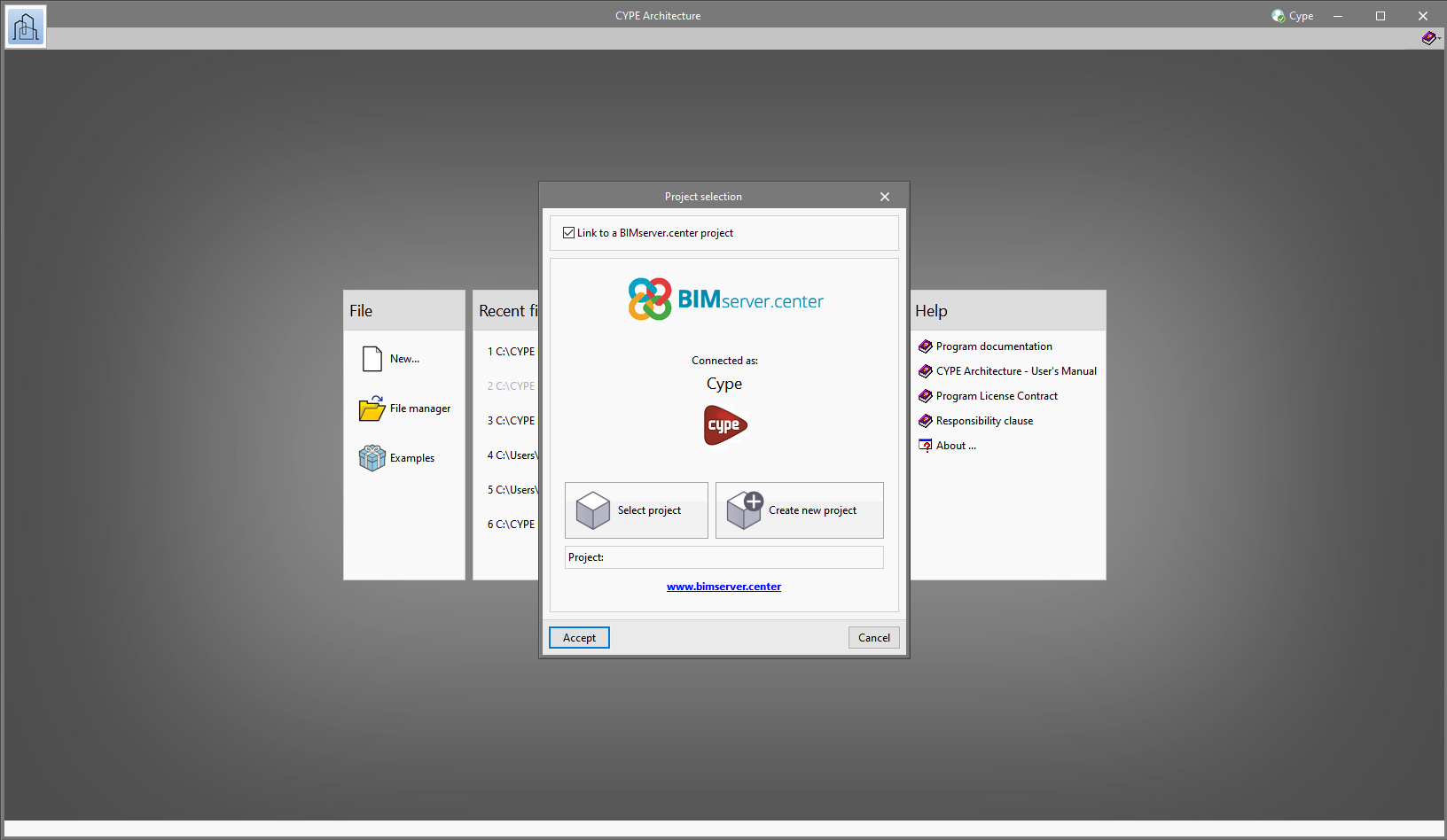
As of version 2022.e, applications that are connected to BIMserver.center communicate with the platform more directly. As a result, it is no longer necessary to specify the user account(s) and projects to be synchronised in the BIMserver.center Sync tool before using the applications. When a user signs in from a desktop application, it automatically establishes the connection to the project.
Previously, some applications required the user to connect to BIMserver.center and select a project in order to start a job. Now, this is no longer necessary and the link will only need to be established when updating the project or sharing a contribution.
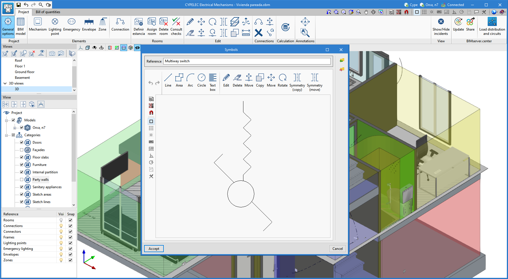
Importing symbols in DXF or DWG format
In the applications listed below, apart from the symbols included to represent elements that are introduced in their corresponding installations, symbols in DXF or DWG format can be imported:
- CYPELEC Electrical Mechanisms
- CYPEPLUMBING Water Systems
- CYPEPLUMBING Sanitary Systems
- CYPEPLUMBING Solar Systems
- CYPEPLUMBING Schematic Diagram
- CYPEHVAC Hydronics
Implementing codes and improving their enforcement
Composite concrete and steel structures
Spanish structural code "Código Estructural"
"Código Estructural (Real Decreto 470/2021)".
Implemented in CYPECAD and CYPE 3D for analysing and checking composite concrete and steel columns.
In previous versions, it was already implemented for analysing, designing or checking other structural elements:
- For analysing and designing concrete structures (v.2022.c) in:
- CYPECAD
- CYPE 3D
- Reinforced concrete cantilever walls
- Embedded retaining walls
- For analysing and checking steel connections (v.2022.c) in:
- CYPE Connect
- StruBIM Steel
- For analysing and designing steel structures (v.2022.d) in:
- CYPECAD
- CYPE 3D
CYPE Architecture
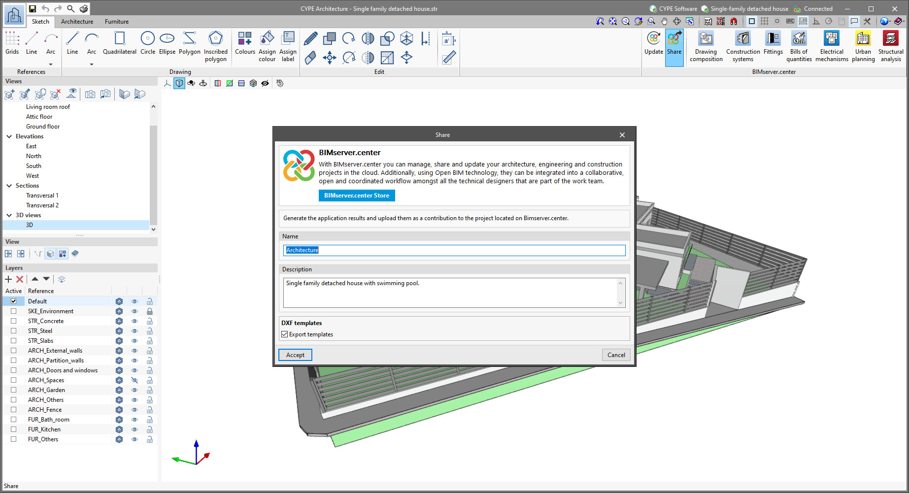
Automatic generation of 2D templates in DWG format
When exporting the CYPE Architecture architectural model in a BIMserver.center project, the program can automatically generate templates in DWG format. These templates will facilitate modelling in other Open BIM workflow programs that are connected to that project, especially for those working in a 2D environment.
The templates are generated from each of the plan views available in the "Views" panel, taking the "Distance to the top plane" of each of them as a reference.
Once the CYPE Architecture architectural model has been exported to the chosen project on the BIMserver.center platform, the templates can be loaded in other Open BIM workflow programs connected to that project, and their visibility can be configured from the "DXF-DWG Template" button in each program.
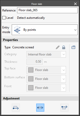
Automatic level detection when inserting architectural elements into 3D views
The program facilitates the introduction of architectural elements and furniture in 3D views, automatically detecting to which level they belong.
This new function can be deactivated, in which case the program will allow the user to manually choose the level where they wish to enter the element.
Search by typology
The functionality of the "Search" button in the "Edit" group in the "Architecture" tab allows searching not only by the reference to the element but also by its associated typology.
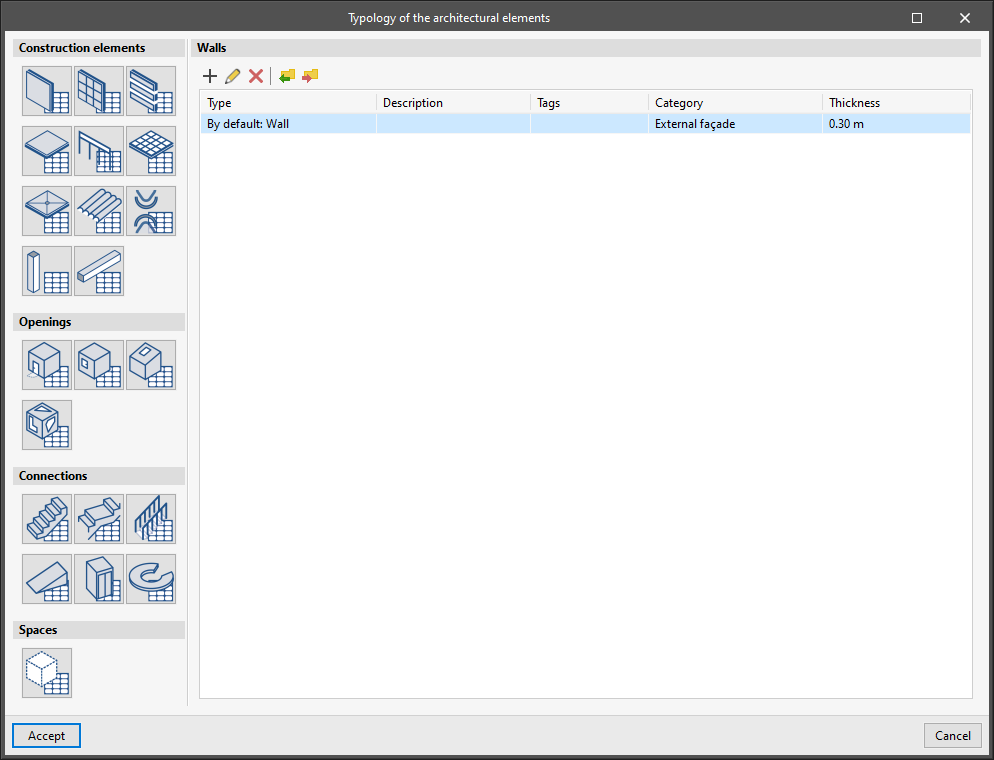
Default typology
When opening a new job, the program will assign a typology by default for each one of the architectural elements.
Typologies simplify the introduction of elements and their later modification and also allow the elements to be classified in other programs in the Open BIM workflow.
Sketch surface information
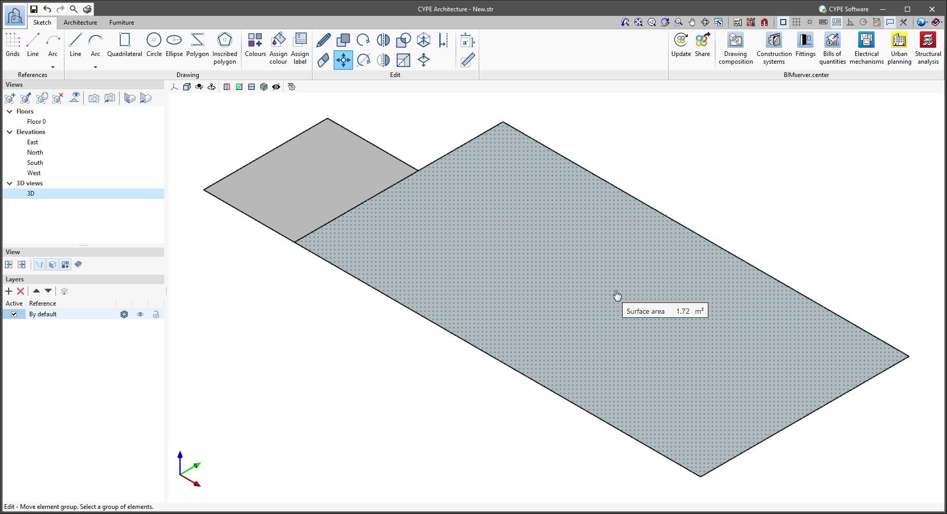
By activating the "Show information texts" feature and hovering over any surface generated with the tools in the "Sketch" tab, the area of that surface will be displayed. Furthermore, the program exports the area information and the label of the surface so that it is accessible in other programs from the Open BIM workflow and in the BIMserver.center viewer.
Copying properties between elements in the "Furniture" tab
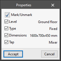
The "Copy properties" tool has been implemented in the "Edit" group of the "Furniture" tab. This tool allows users to copy properties between the same type of elements (Reference, Level, Colour, etc.).
To copy the properties of an element, follow the steps below. Please note that you can only copy properties between elements of the same type.
- Click on the "Copy properties" button in the "Edit" menu.
- Select the item for which you wish to copy the properties.
- A panel will appear with a list of properties that can be copied and their values.
- Choose the properties you wish to copy and accept the panel.
- Select the elements to which you wish to copy the chosen properties.
- Right-click the mouse and the properties will be transferred to the selected elements.
Open BIM Construction Systems
Update for assigning construction systems
The "Update construction systems according to the typologies of the architectural model" option has been added to the configuration panel for updating the BIM model. When it is activated, the existing connection of the construction systems with the elements in the architectural BIM model will be removed and will be re-established based on architectural typologies. This link can be edited via the "Assign systems" option available in the "Edit" group in the application’s toolbar.
Technical data
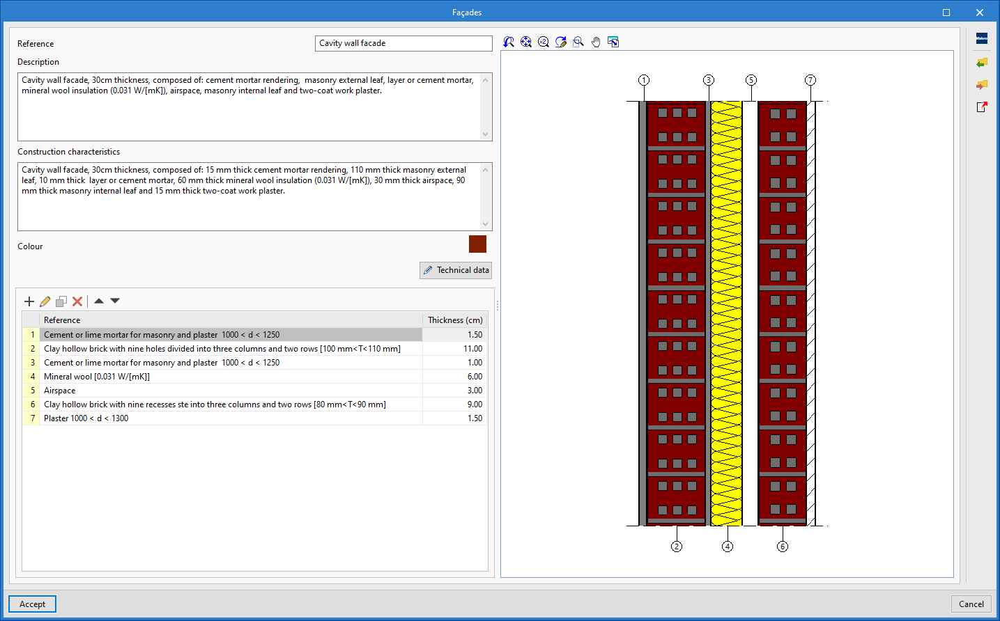
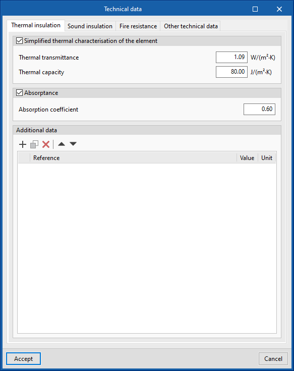
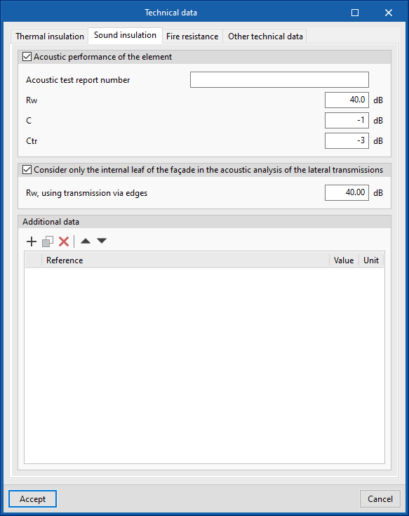
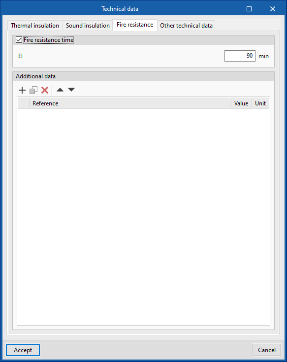
As of version 2022.e, technical data can be assigned to construction systems. To do this, the "Technical data" option has been added in the definition panel of each construction system. Introducing these parameters is optional and in this version (2022.e) we can find them grouped into the following categories:
- Thermal insulation
- Sound insulation
- Fire resistance
- Other technical data
In "Other technical data" the user can create new groups of data and add custom parameters manually. In the other categories, some predefined parameters can be found, as well as a list for entering custom parameters.
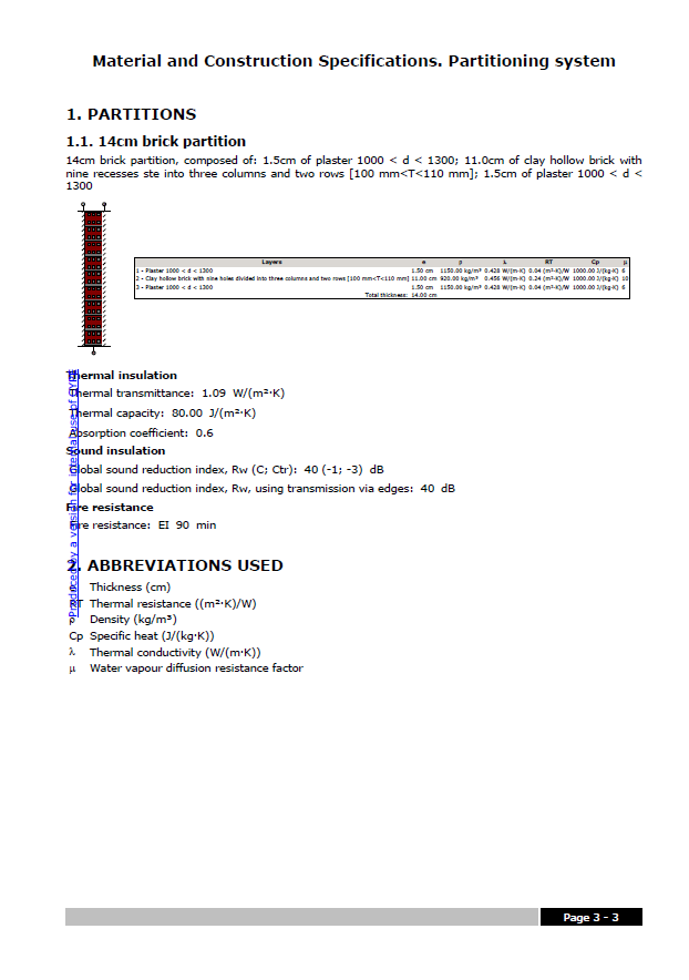
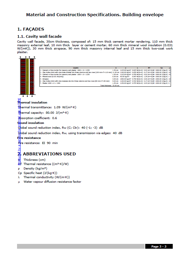
The technical data is included in the Material and Construction Specifications, both for the building envelope and partitioning system. These documents can be exported to the BIMserver.center project and read by other applications.
Sound absorption coefficients in the layers of a construction system
An option for entering the sound absorption coefficients for 500, 1000 and 2000 Hz bands in the layers forming construction systems has been added. The sound absorption coefficients in the internal and external surfaces of the construction system are included in the Material and Construction Specifications, both for the building envelope and partitioning system. These documents can be exported to the BIMserver.center project and read by other applications.
Thermal parameters for the layers of a construction system included in their documents
As of version 2022.e, the thermal parameters entered for the layers that make up a construction system appear in the list of layers displayed in the Material and Construction Specifications, both for the building envelope and partitioning system. These documents can be exported to the BIMserver.center project and read by other applications.
Open BIM Layout
Improvements in the "3D scene" library
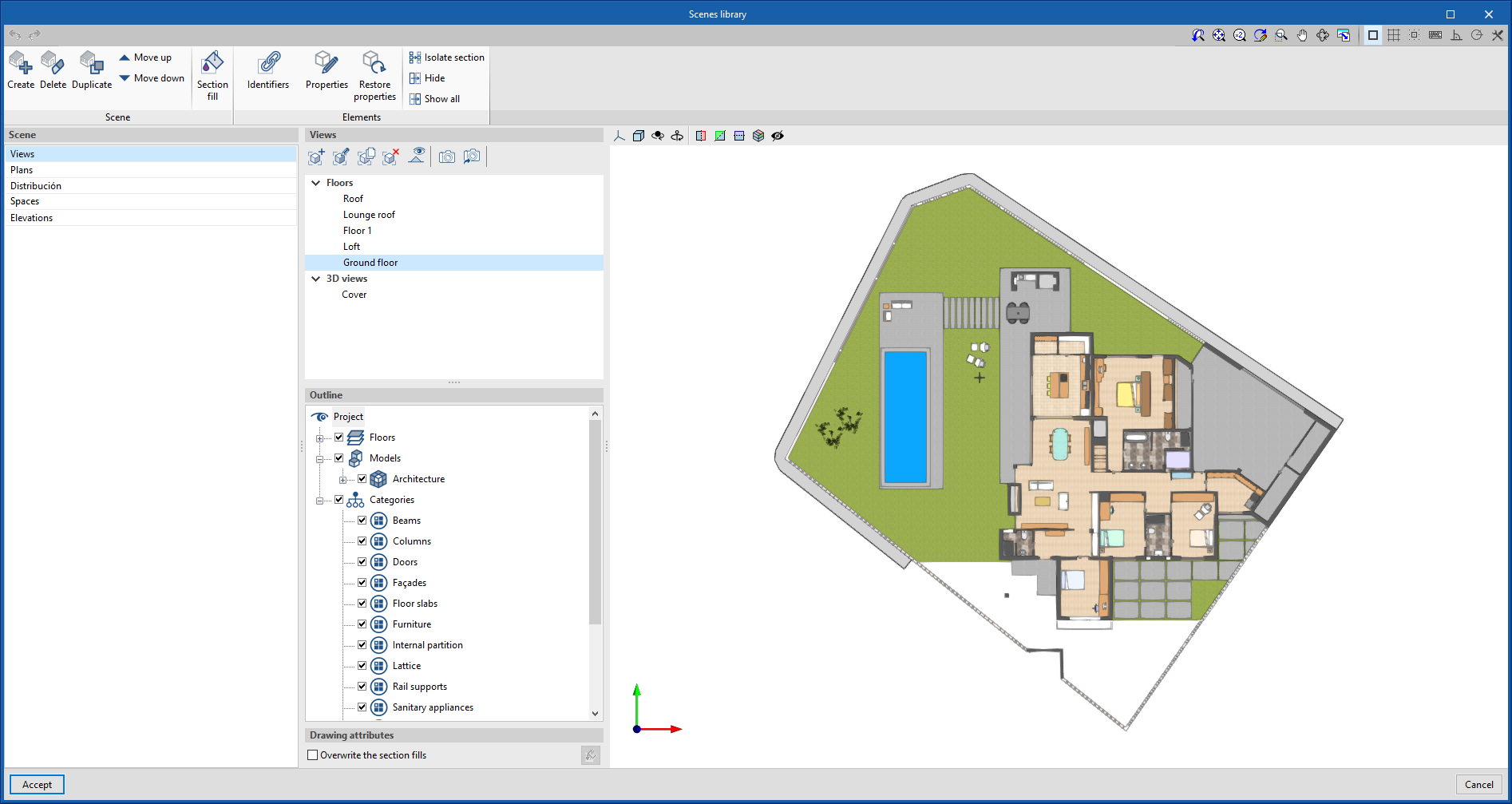
The "3D Scene" library has been improved to include the following features:
- Reorganisation of the scene library interface to make it easier to use.
- New tools that allow individualised editing of elements in the scene:
- Show/Hide elements individually.
- Editing elements’ properties such as drawing mode (normal, transparent or wire).
- Filling in sections individually.
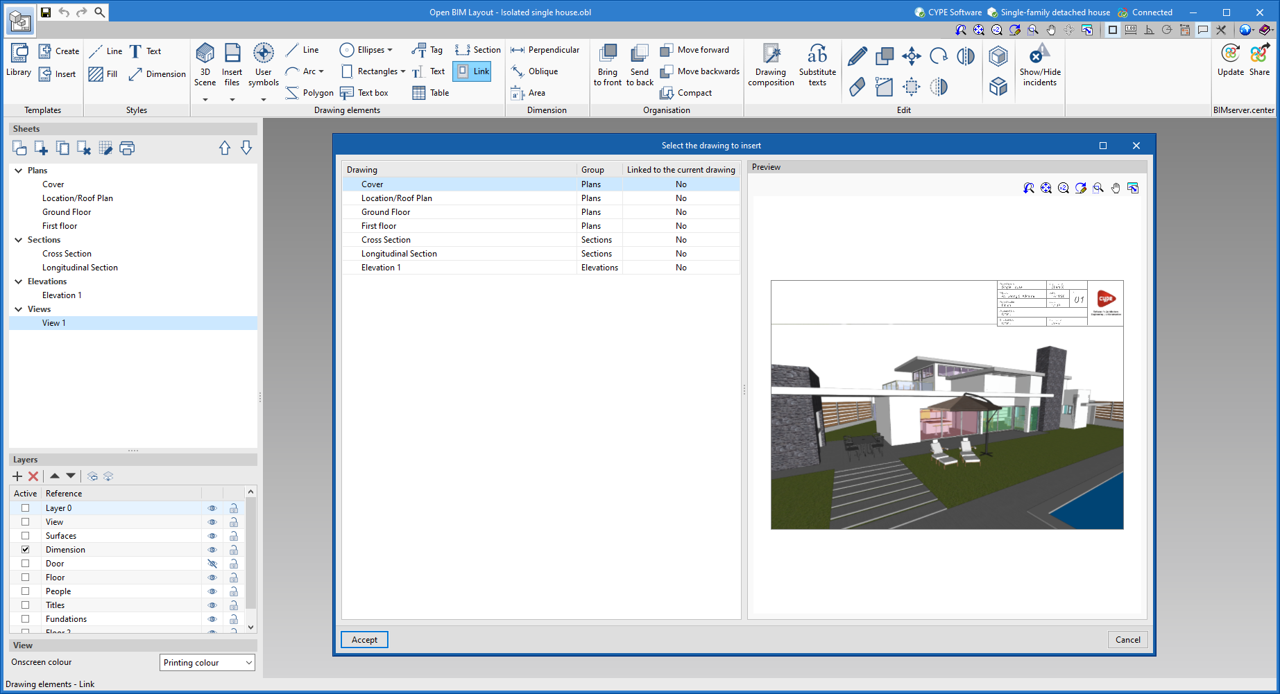
Link sheet
This new feature allows the content of one sheet to be displayed within another. When linking the content, any changes made to the original sheet will be automatically updated in the sheet containing the link.
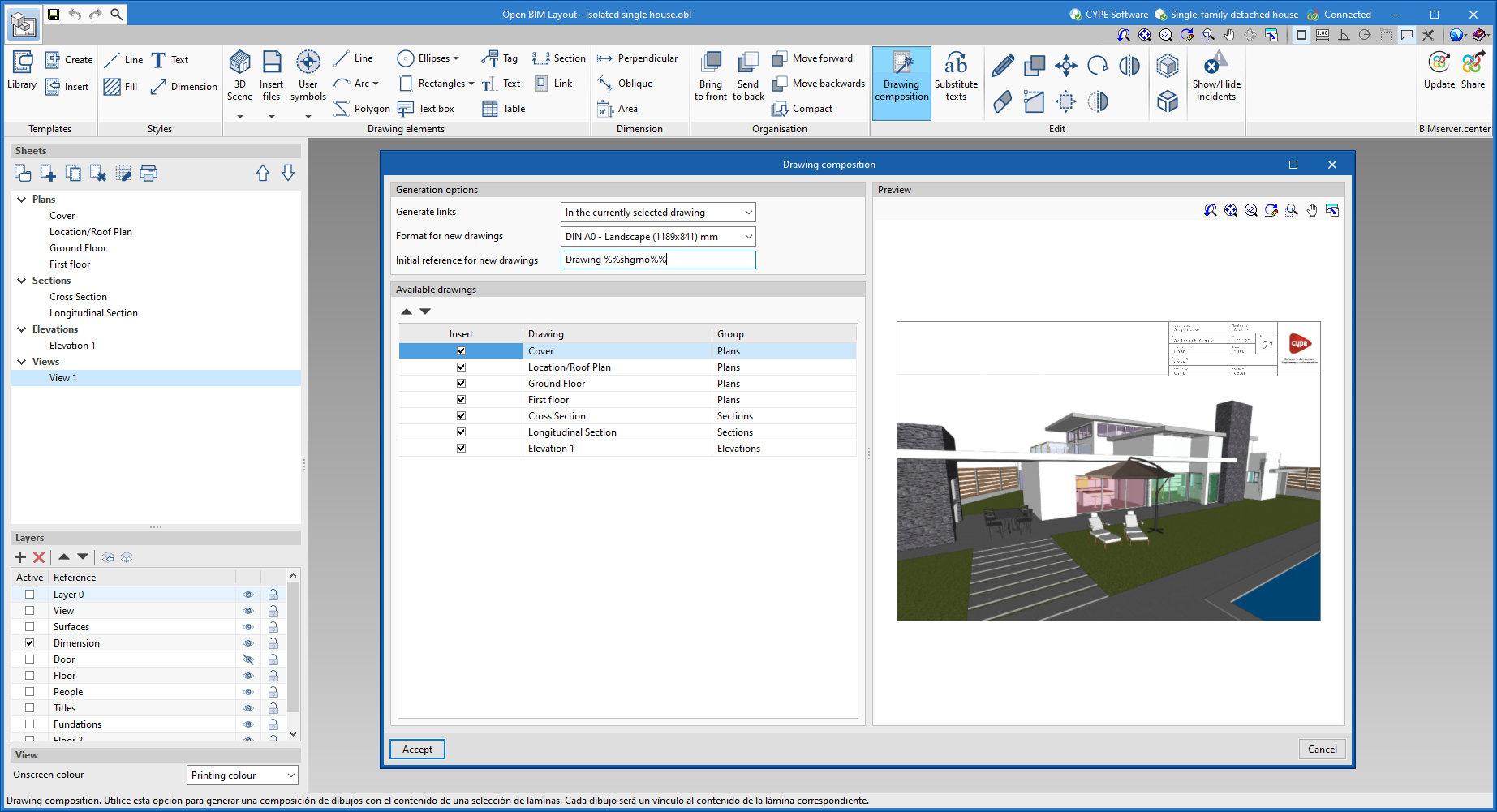
Automatic sheet composition
A new feature that allows users to automatically generate a composition of drawings from a selection of sheets. Each drawing is inserted as a link to the content of the corresponding original sheet.
Dimension style
Within the dimension styles, the type of unit (metres, centimetres, millimetres, feet or inches) can be indicated.
CYPECAD
Creating construction details with an image
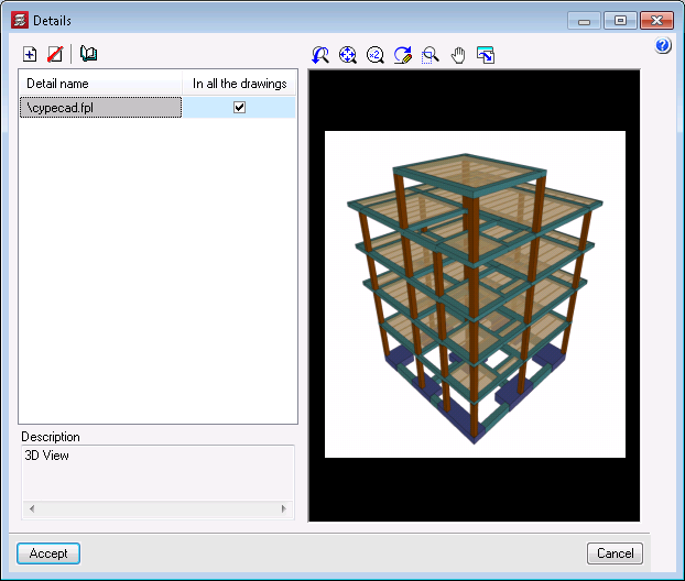
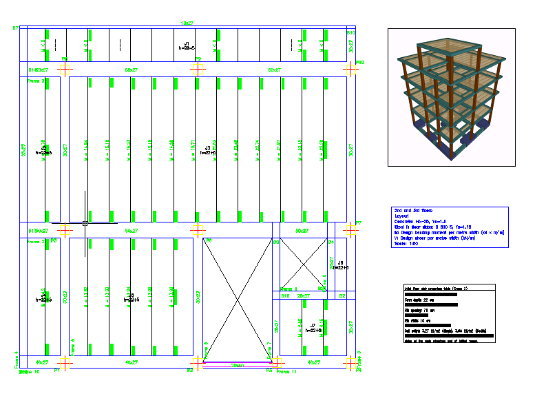
In the "Add user information" option (Drawing editor - Details – Add user information), details can be created by importing an image. Up until the previous version (2022.d), details could only be created from DXF and DWG files. In the import process, the final size of the image in the drawing can be defined.
Other improvements and corrections
Version 2022.e of CYPECAD includes other minor improvements and corrections of the program for certain cases:
- Final design report
In the final design report, warnings concerning concrete wall checks have been added. - Checking the results of wall openings
An error that occurred when checking the results for wall openings when these were defined on a floor with continuous reinforcement has been fixed. - Editing frames
When editing beam frames, the possibility to define "Length with straight extension" in "Longitudinal reinforcement > Edit hooks" has been added. - Checking fire resistance
An error that could sometimes occur when checking a series of steel sections in beam frames, when checking fire resistance, has been fixed. - Sharing in BIMserver.center
The "BIMserver.center > Share" option panel has been improved, it was not displayed correctly at times when the screen resolution is small. - Sharing in BIMserver.center
An error that could occur in the "BIMserver.center > Share" option when generating the reinforcement for column starts has been fixed. - Punching shear check
An error that occurred in the punching shear check process when there is a mat foundation with a very small surface in contact with a column has been fixed. - Deleting or dividing groups
An error that occurred when deleting or dividing a group in the case of walls with blocked reinforcement has been fixed. - Beams information
An error that occurred when selecting a wall that starts on top of another wall in the "Information - Beams" option has been fixed. - Bills of quantities
The measuring of formwork for beams in the "Bills of quantities" option has been improved. In some cases, an element with a 0 m2 surface was added. - Changing a job’s code (EHE-08 to Código Estructural)
The transformation of a job initially created with code EHE-08 when it is updated to code "Código Estructural" has been improved. As well as adapting the "Environment" selection in "General data", it is adapted in each beam that has a specific assignment. - Checking the baseline shear
The checking of the base shear for walls without external fixity in contact with column starts with external fixity has been improved. - Checking geometry
An error that occurred in the "Check the geometry of the current group" and "Check the geometry of the current group and higher groups" options, if sloped beams had been introduced in the job, has been fixed. - Analytical model
An error that could sometimes occur when obtaining the analytical model of a wall whose axis did not match the centre and that ended in a sloped slab has been fixed. - Assign walls
The "Assign walls" option has been improved in order to consider embedded or crown beams with specific features.
CYPECAD and CYPE 3D
"Channel with stiffened web" type in BS 5950-5:1998 cold formed steel sections
In version 2022.e, "Channel with stiffened web" type cold formed steel sections have been included for beams and columns (CYPECAD) and for bars (CYPE 3D) when the selected standard is BS 5950-5:1998.
CYPE Connect and StruBIM Steel
Selection of load cases considered in the analysis
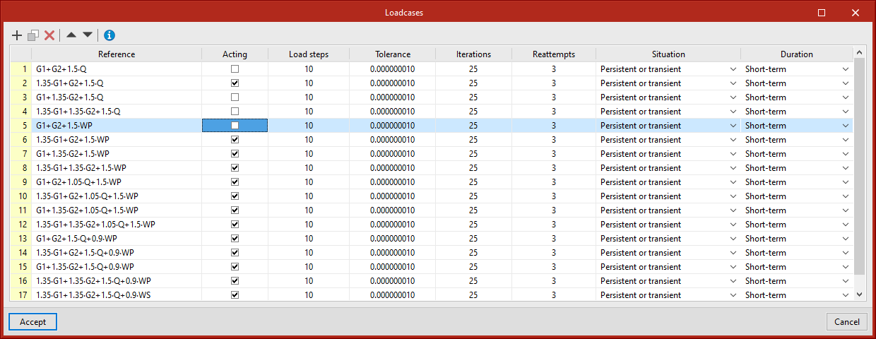
As of version 2022.e, users can select the load cases to be considered when analysing a joint. To do this, the "Acting" column has been added to the table in the "Load case" dialogue box, allowing the desired load cases in the analysis to be activated or deactivated.
Section series library
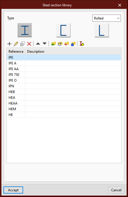
The possibility of using the predefined section libraries that are available in other structure design software such as CYPECAD and CYPE 3D has been incorporated.
Improvement for importing bars
In version 2022.e, the importation of sections from the BIM model has been improved. It is now possible to select or modify the sections for each of the typologies defined in the IFC file.
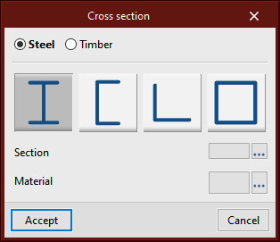
In the "Bars" step of the BIM model import assistant, a list of detected section types is displayed. In the "Cross section" column, the section to be assigned in CYPE Connect will be indicated. By clicking on each cell, the cross section and material selection panel can be accessed.
When possible, the program generates a proposal based on the information available in the BIM model. Users can select the sections they wish to import as well as carry out manual assignments when deemed necessary or when automatic detection has not been possible. The assignment made is saved for subsequent imports.
CYPELEC Electrical Mechanisms
New 3D work environment
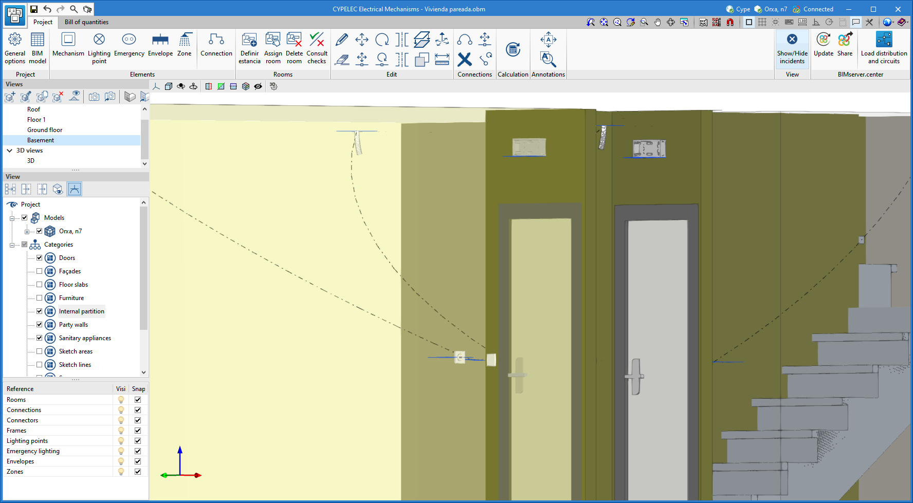
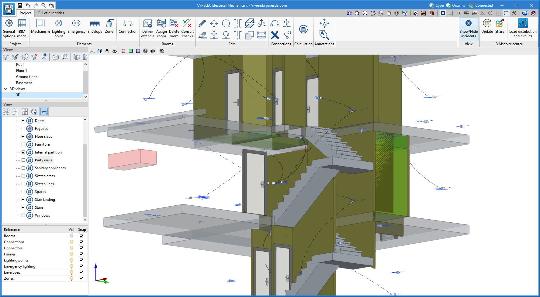
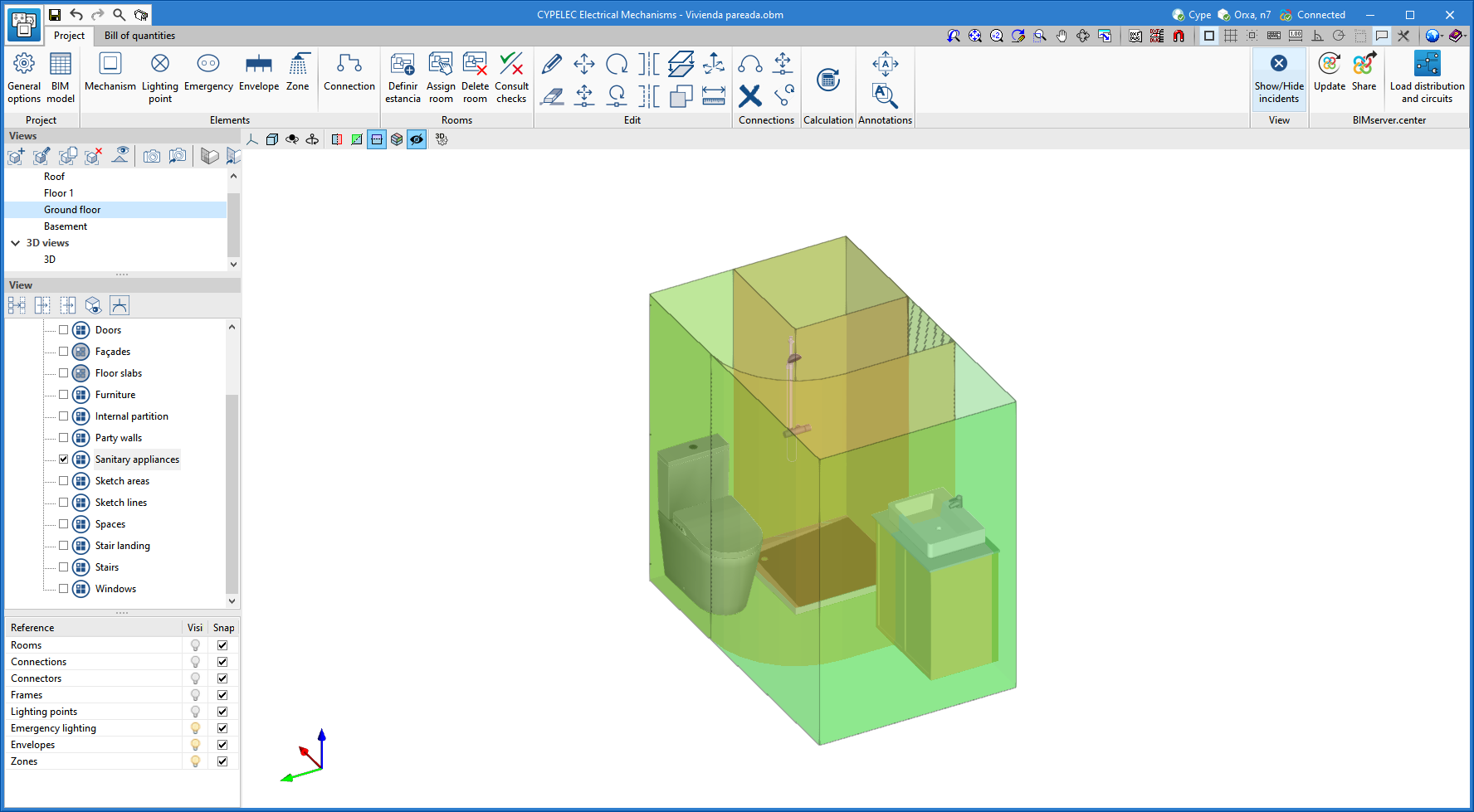
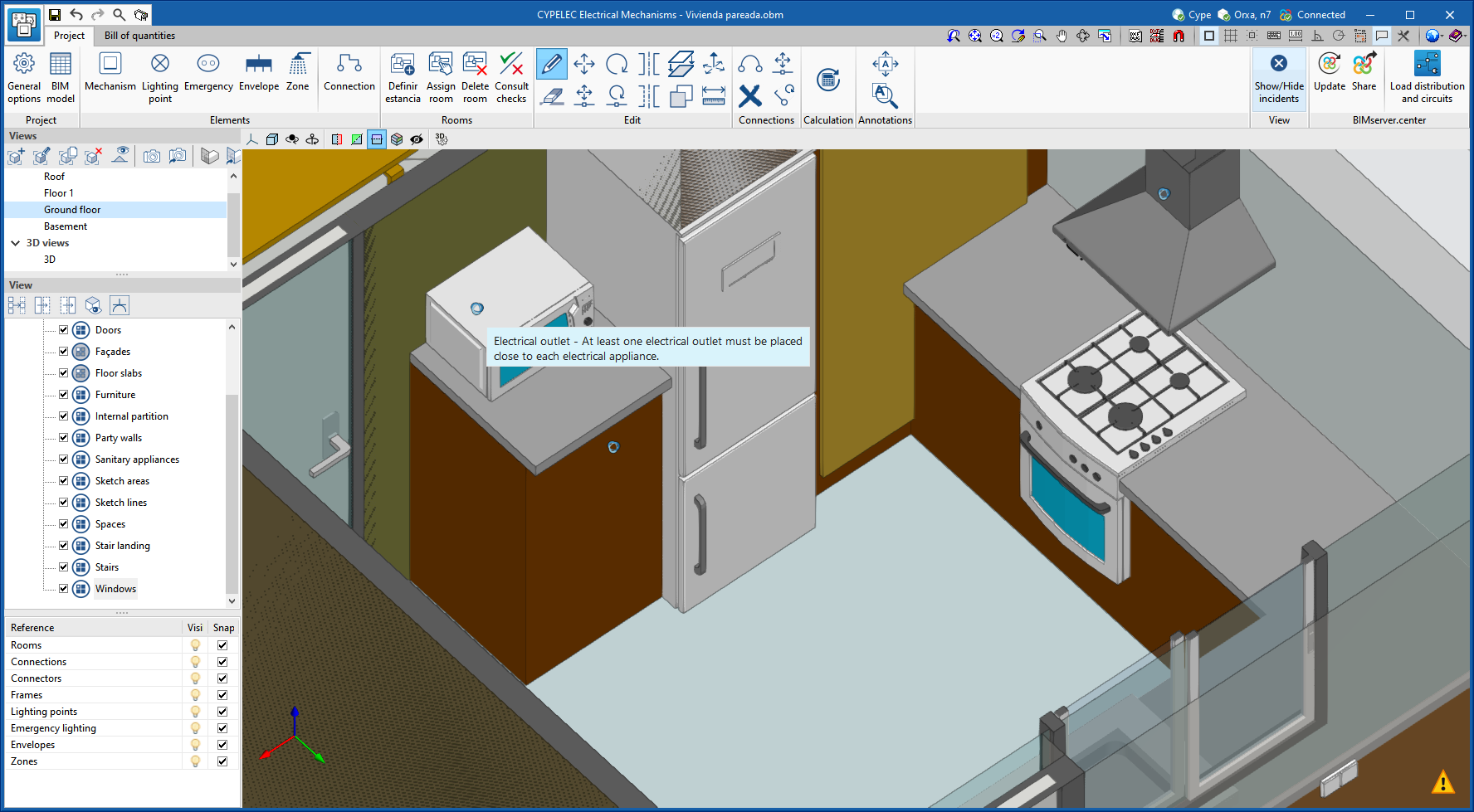
CYPELEC Electrical Mechanisms changes from a 2D environment to a new 3D work environment, achieving greater capacity in the architectural modelling of terminal elements in electrical and telecommunications installations.
The new 3D work environment provides:
- Greater geometric precision when positioning ceiling lighting points, wall lighting points, emergency lighting and electrical mechanisms: switches, multiway switches, sockets, audiovisual connectors and telephone connectors.
- Improvement in the connection of lighting circuits and points of use between switches and lighting points, including those in stairwells between floors.
- Improvement in the representation of electrical zones in rooms containing a bath or shower.
- Improvement in the requirements for placing sockets in proximity to electrical appliances.
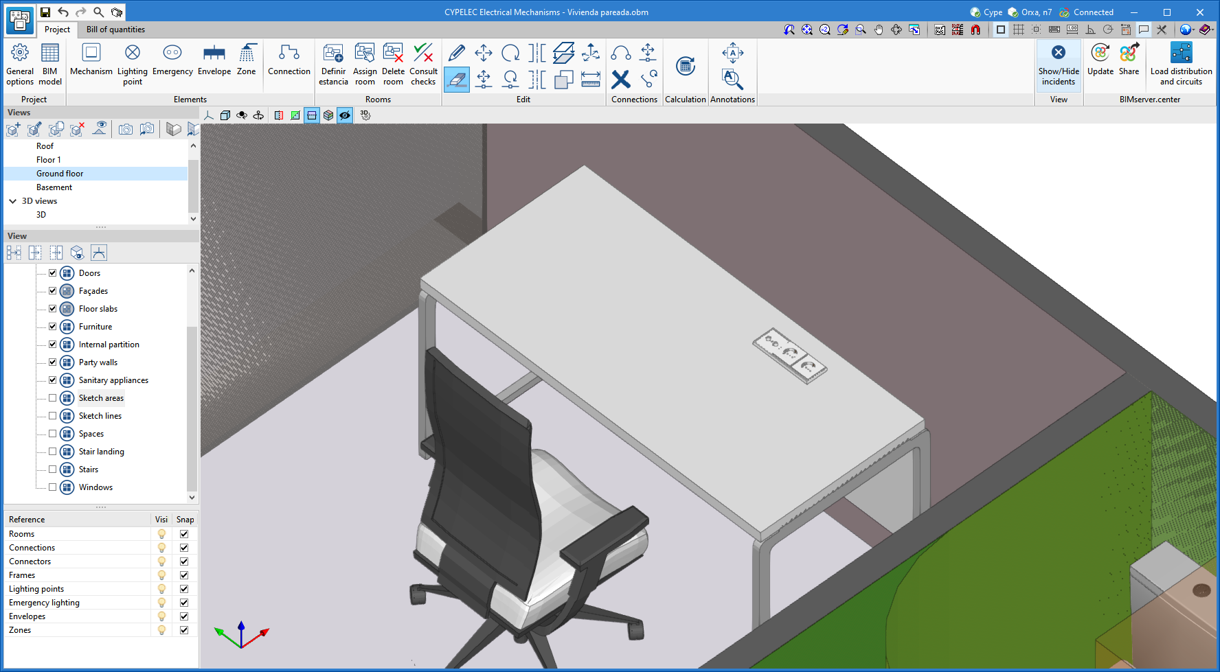
Horizontal positioning of electrical mechanisms
Mechanisms can now be introduced in a horizontal position to be placed on technical floors, worktops or furniture.
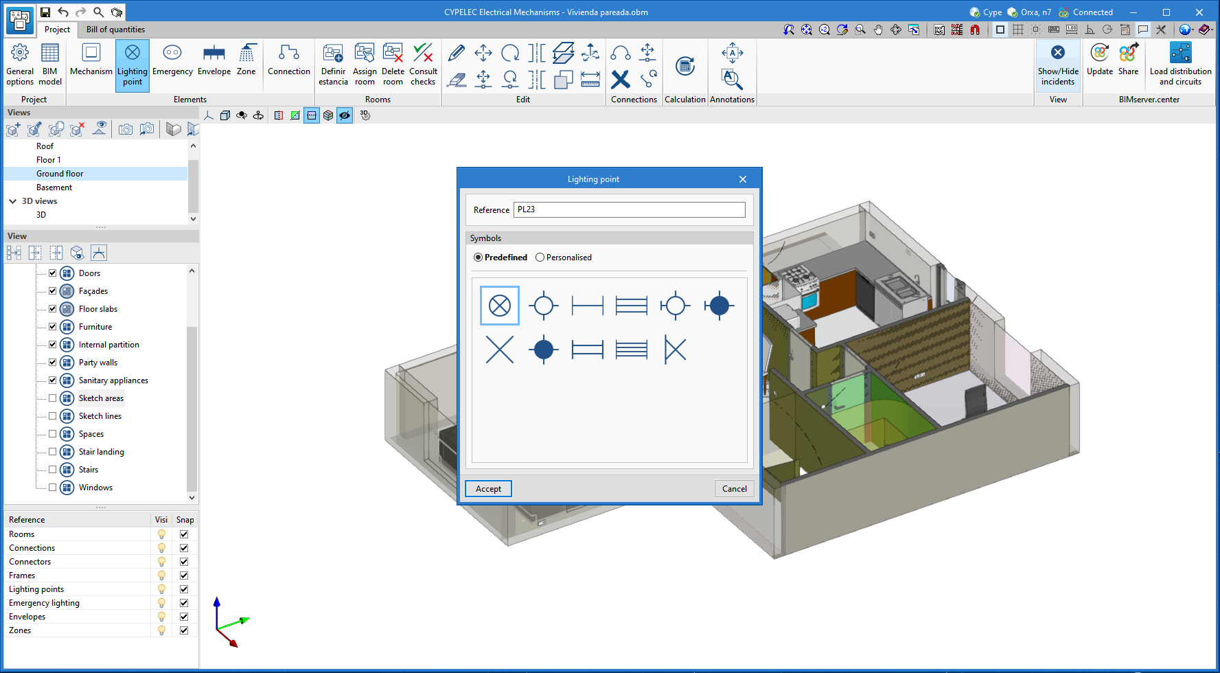
Additional symbols for normal and emergency lighting points and for electrical outlets
The number of electrical symbols that users can select for normal (wall or ceiling) lighting points, emergency lighting and sockets is extended.
CYPELEC PV Systems
Maximum loss due to orientation and slope
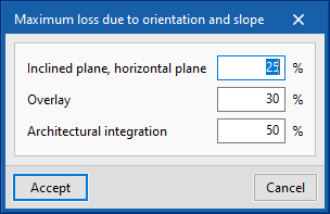
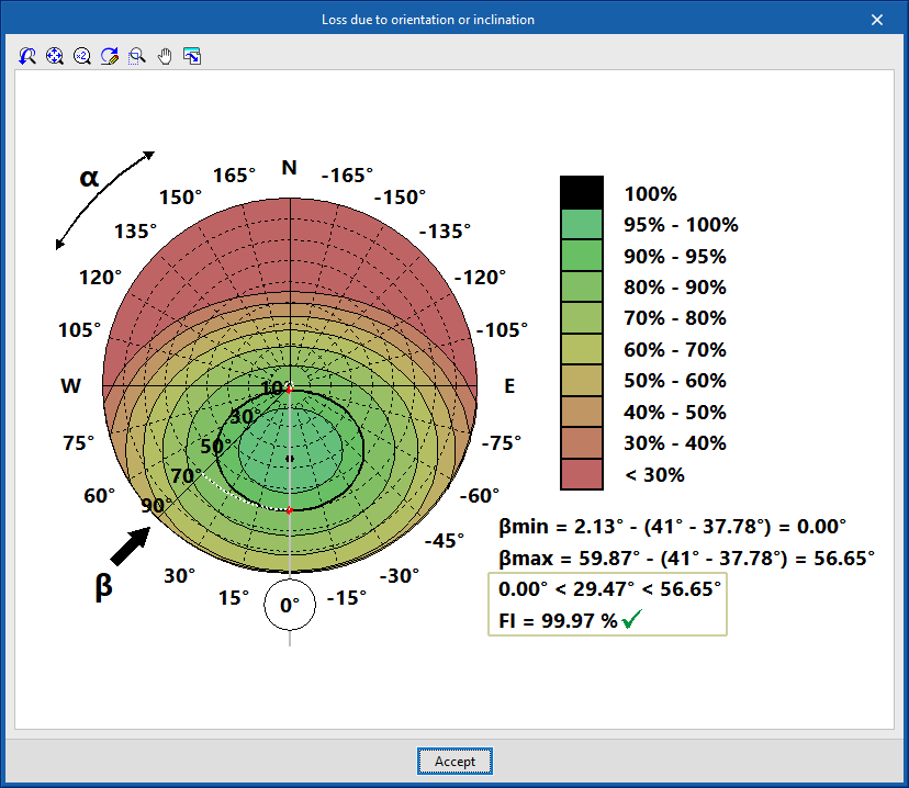
CYPELEC PV Systems version 2022.e allows users to define the percentage of maximum loss due to orientation and slope (General Options > General Parameters > Maximum loss due to orientation and slope) for all types of photovoltaic panel installations (Inclined plane, Horizontal plane, Overlay and Architectural integration).
This way, depending on the type of installation, the maximum and minimum slopes of the panels, as well as the maximum loss due to orientation and slope for each panel, will be checked.
"Production-Consumption analysis" document in "Total values" of the energy pre-design
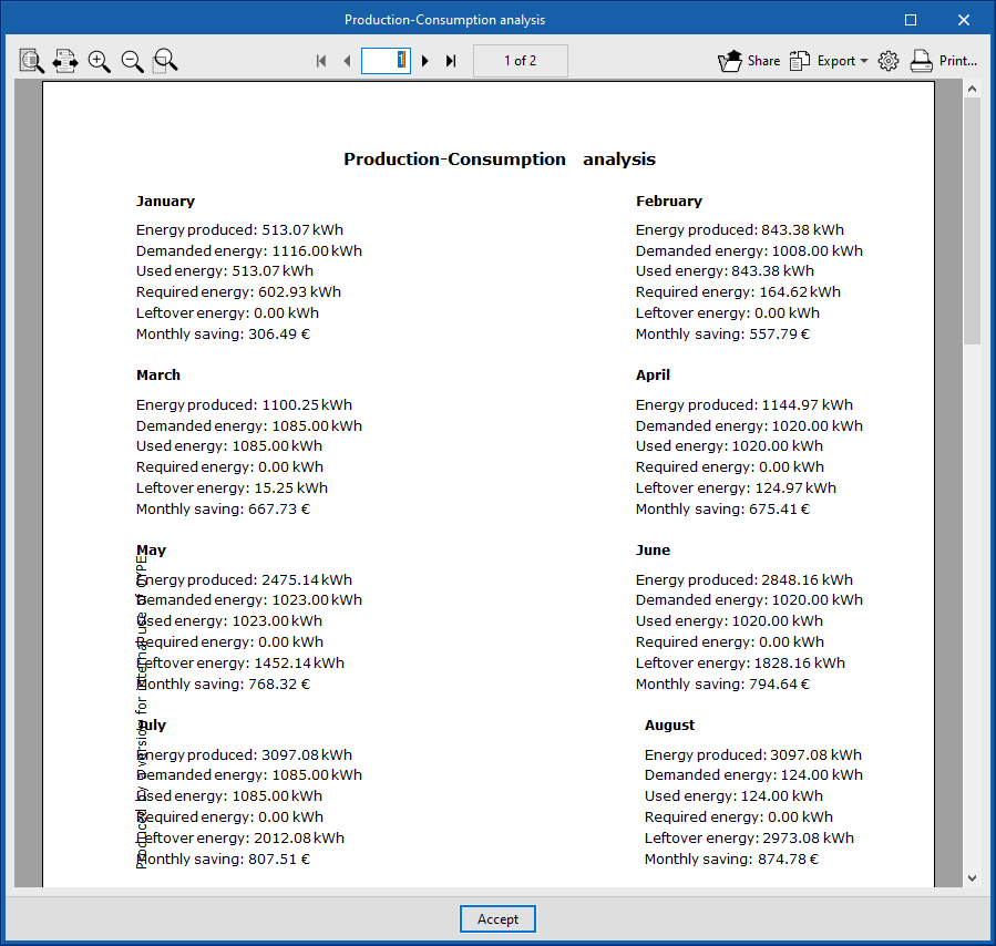
Version 2022.e of CYPELEC PV Systems allows the "Production-Consumption analysis" document to be generated in the "Energy pre-design" work window for installations that are "Connected to the network" and the "Total values" of production and consumption.
The generation of this document was already implemented in version 2022.c of CYPELEC PV Systems for installations that are "Connected to the network" and "Hourly values" of production and consumption.
This document can be exported in different text formats.
Arquimedes
New "Establish as default settings" option when editing the location codes in a bill of quantities
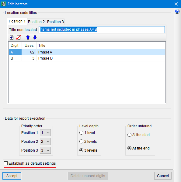
The Establish as default settings option allows the editing of location codes in a bill of quantities to be saved as user configuration so that they can be used in other jobs.
Location codes allow for the elaboration of a bill of quantities composed of other "sub" bills of quantities (such as, for example, a job made up of phases), indicating for each quantities subtable, in the header of the subtable and in the "Loc" column, its situation in the execution of the job. This location is carried out by means of an alphanumeric code of up to three characters which defines the hierarchy levels the user wishes to establish in the bill of quantities.
Bill of quantities of Revit models
Comments composition for quantity lines
User properties can be used for forming comments and the formation of comments of elements using a material is improved.
Open BIM Cost Estimator
Price adjustment
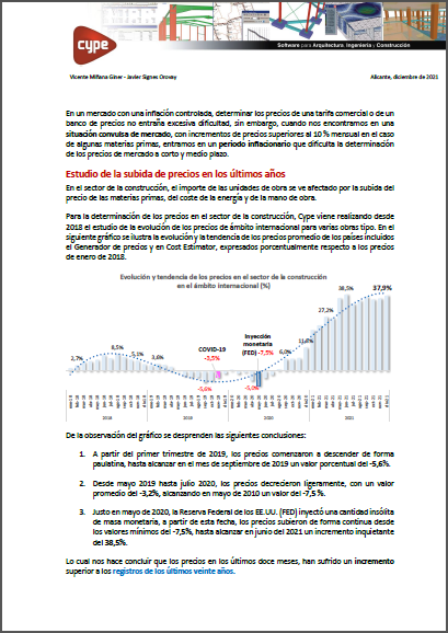
In light of the new inflationary situation, an overview of the evolution of construction costs for the 2018-2021 period can be found in the document below, as well as the main causes of price increases and the criteria adopted in the updates of Open BIM Cost Estimator.
Inclusion of more countries
A further six countries have been included for the geographical location (Phase I: Preliminary analysis -> Geographic and economic data -> Geographical location - > Country): Norway, Slovakia, Bangladesh, Egypt, South Africa and Central African Republic.
Return to the 2022 version download area
Tel. USA (+1) 202 569 8902 // UK (+44) 20 3608 1448 // Spain (+34) 965 922 550 - Fax (+34) 965 124 950
