NEW PROGRAMS AND MODULES
NEW FEATURES OF EXISTING PROGRAMS
- New features common to several programs
- Open BIM aliaxis
- Code implementation and improvements in its application
- CYPE Architecture
- Intersection solutions
- New space generation
- New glazed surface button
- Export to IFC of new quantities sets
- Improved area measurement
- Improved wall and floor slab introduction
- XZ axis rotation in the Architecture tab
- Choosing the height of the drain in slope formation
- Height of louvres and curtain walls
- Open BIM Layout
- CYPECAD and CYPE 3D
- CYPECAD
- CYPE 3D
- StruBIM Steel
- StruBIM Shear Walls
- StruBIM Rebar
- CYPECAD MEP and IFC Builder
- CYPELEC Distribution
- CYPELEC Core, CYPELEC Distribution, CYPELEC Electrical Mechanisms
- CYPELEC PV Systems
- CYPELEC Grounding IEC and CYPELEC Grounding IEEE
- CYPETEL Systems
- CYPETEL Schematics
- CYPEHVAC Ductwork
- CYPETHERM LOADS and CYPETHERM EPlus
- CYPETHERM EPlus
- Arquimedes
- Open BIM Quantities and applications with the Bill of Quantities tab
- Open BIM Quantities
- Applications with the Bill of Quantities tab
- Return to the 2021 version download area
NEW PROGRAMS AND MODULES
Open BIM aliaxis ISEA
"Open BIM aliaxis ISEA" is a free program with which users can configure wastewater treatment systems (originating or not from domestic use), using products from the ISEA catalogue of aliaxis' REDI company.
Users, by means of a few simple steps, enter the properties of the wastewater system: number of users, location of the building, type of discharge, and the program automatically designs the appropriate product to treat the wastewater. The configuration of the installation is associated with a technical and commercial offer that can be sent directly to REDI to receive technical assistance or to confirm the order.
More information (in Italian).
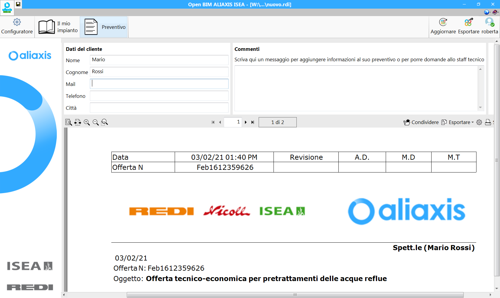
Open BIM ISOVER
"Open BIM ISOVER" is free software where users can select insulation and fire protection materials of the manufacturer ISOVER, for ventilation ducts in BIM projects.
The program is integrated into the Open BIM workflow, which implies it can read the geometry of a building that has been created by any geometric generator that operates with the IFC standard, and participates in an integrated manner in the open BIM workflow via the BIMserver.center platform.
If the BIMserver.center project that connects to Open BIM ISOVER also includes a BIM model with the distribution of the ventilation ducts, the program will read the distribution of the ducts that can be found in the project as well as their dimensions, and can cover them with the insulation material that has been selected from the ISOVER catalogue. Users can modify the selected materials based on fire protection requirements (calculated in CYPEFIRE CTE) and thermal insulation requirements (calculated based on the RITE).
"Open BIM ISOVER" provides:
- A materials report (materials schedule).
- A design and code justification report.
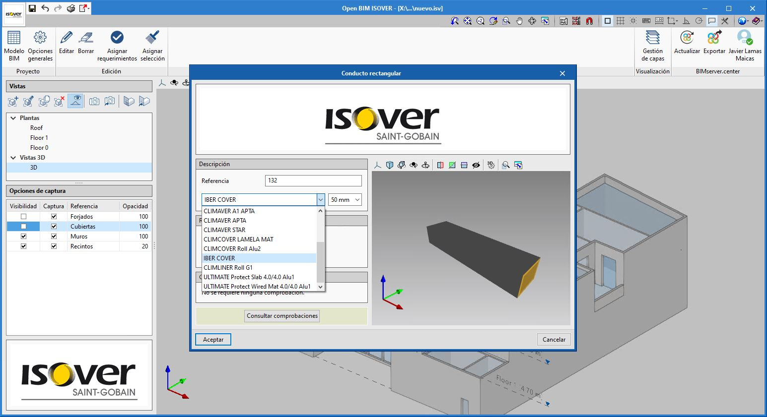
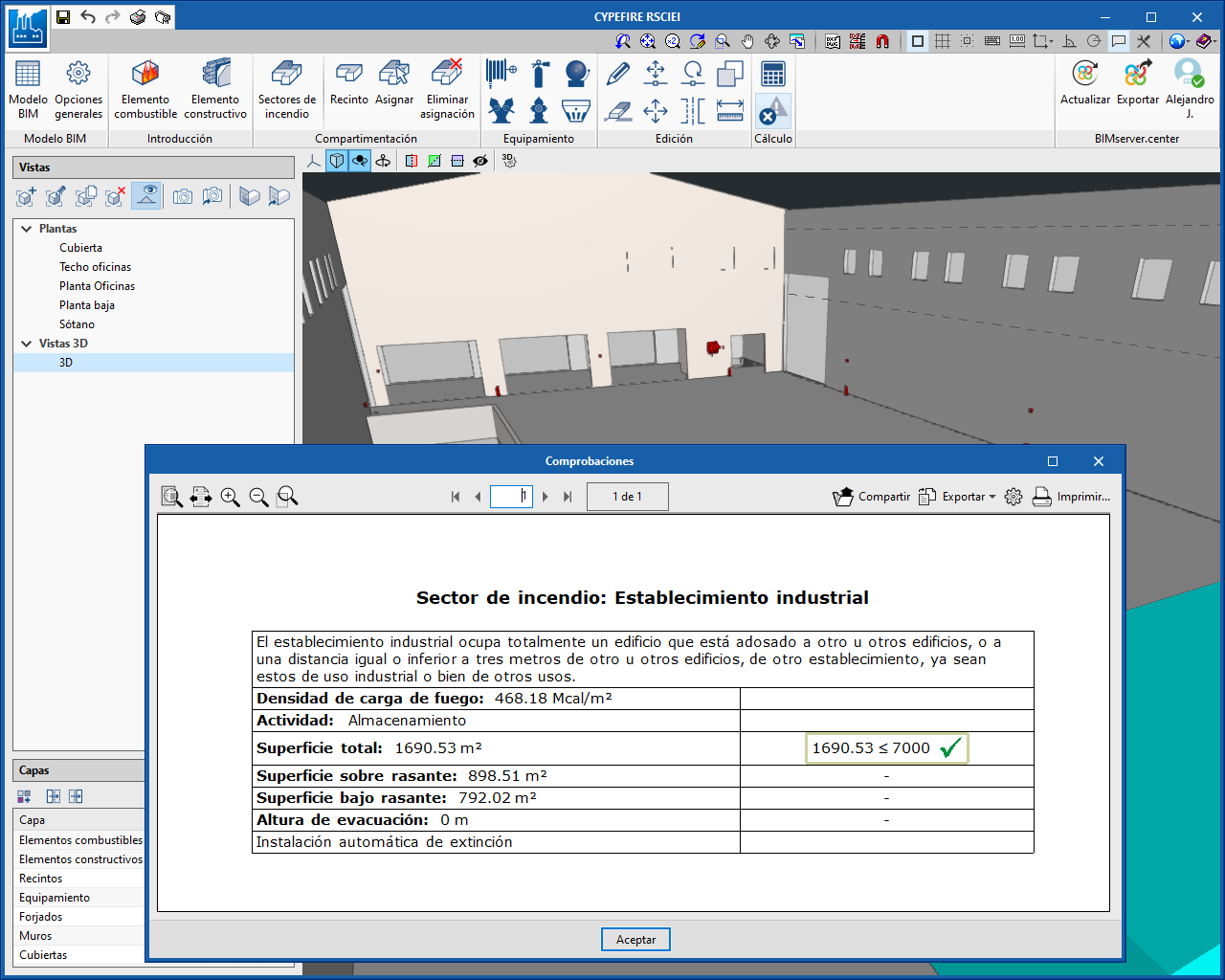
CYPEFIRE RSCIEI
"CYPEFIRE RSCIEI" is a tool created to help the designer during the design and checks of the geometric features of the building and fire protection installations. "CYPEFIRE RSCIEI" details the requirements and carries out the necessary checks to justify compliance with the Spanish Reglamento de seguridad contra incendios en establecimientos industriales.
This tool is integrated into the Open BIM workflow via the BIMserver.center platform.
More information (in Spanish).
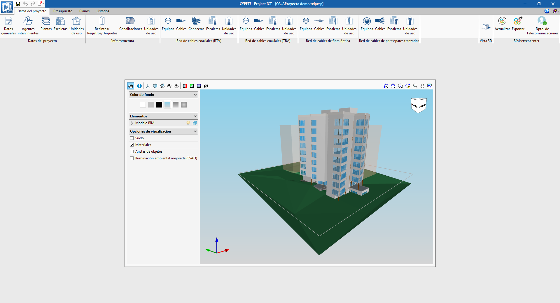
CYPETEL Project ICT
"CYPETEL Project ICT" is a program created to assist the user in generating the documents of the technical project for the Infraestructura Común de Telecomunicaciones, following the technical specifications of the Spanish code (Real Decreto 346/2011, Orden ITC/1644/2011, and Orden ECE/983/2019). CYPETEL Project ICT is integrated into the Open BIM workflow via the BIMserver.center platform.
"CYPETEL Project ICT" together with "CYPETEL Systems" and "CYEPTEL Schematics" completely replace the "CYPETEL ICT" program, which will be discontinued as of this version.
More information (in Spanish).
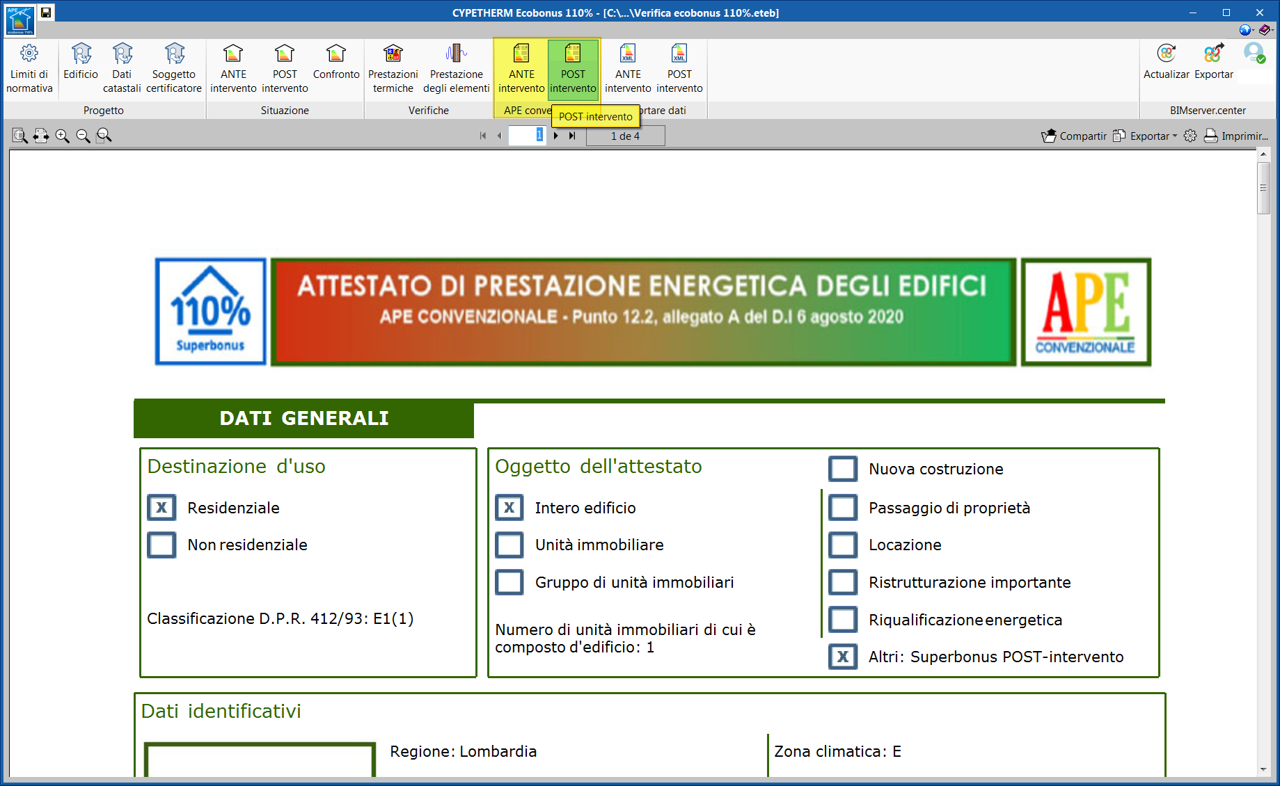
CYPETHERM Ecobonus 110%
"CYPETHERM Ecobonus 110%" can only be installed in Italian and is a free program to generate the pre-construction and post-construction "APE convenzionale", to check the minimum jump of two energy classes, in compliance with "art. 119, Decreto Rilancio 2020". The program is integrated into the Open BIM workflow via the BIMserver.center platform, which allows users to exchange data and information in an agile and collaborative way.
More information (in Italian).
NEW FEATURES OF EXISTING PROGRAMS
New features common to several programs
Element selection tool
In applications that have a drawing area, when there are no active operations, there is usually a tool running, such as the "measure" tool (in IFC Builder) or the "edit" tool (in CYPELUX). As of the 2021e version, some programs will incorporate a tool that is able to select elements of the model and carry out different operations on them. This tool will be available when no option in the application has been activated, and allows the following actions to be carried out:
- Select an element
This is selected by clicking on an element in the model. When an element is selected, as well as being highlighted in the work area, its handle points will be shown so that the user can modify its position or geometry. - Select several elements
If the "CTRL" key is held down whilst selecting elements of the model they will be added to the selection. Users can click on an individual element or use a selection box to add several objects at the same time.
- Remove element from selection
To remove an element from the selection hold down the "SHIFT" key whilst clicking on the elements to be removed. In this case, the selection box can also be used to select various elements at the same time.
- Cancel selection
By pressing the "ESC" key or right clicking the mouse the selection is cancelled. - Edit element
Double clicking on an element will display the edit window associated with the component, if it is able to be modified. - Delete selected elements
By pressing the "DEL" key the selected elements are deleted from the model. - Copy selected elements
Pressing the "CTRL + C" keys copies the elements of the selection. The cursor position upon executing the command is considered the base point of the copy, whilst the user must click on the drawing area to enter the final point. - Move selected elements
Pressing the "CTRL + X" keys moves the elements of the selection. The cursor position upon executing the command is considered the base point of the movement, whilst the user must click on the drawing area to enter the final point.
The new selection tool will be progressively incorporated into the applications that have a drawing area. The following applications will have this tool in the 2021e version:
- Open BIM Lightning
- Open BIM Panasonic
- Open BIM Architecture
Select and snap nearby elements
When various elements are nearby to each other, or directly overlapping in a model view, it can be difficult to select one of them to carry out an operation. In order to avoid this problem it is now possible to use the "TAB" key to scroll through the elements close to the cursor, which will be highlighted for easy identification. By pressing the "SHIFT + TAB" combination of keys, the elements can be scrolled over in reverse order.
On the other hand, when adding or editing a model component with several object snaps activated, there may also be several valid object snaps at the cursor position. In this case, the TAB key allows us to scroll through the possible options before accepting the introduction.
Multiple selection
The operation of the multiple selection of elements in applications that use it in their editing tools (copy, move, rotate, delete, etc) has been modified. Now, during the process selection, holding down the SHIFT key whilst clicking on an object allows it to be removed from the current selection. The SHIFT key combination can also be used in a selection box in order to deselect several components of the model at the same time.
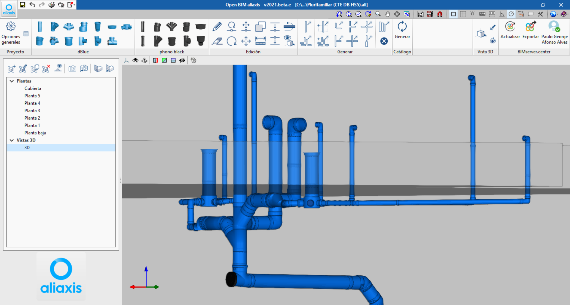
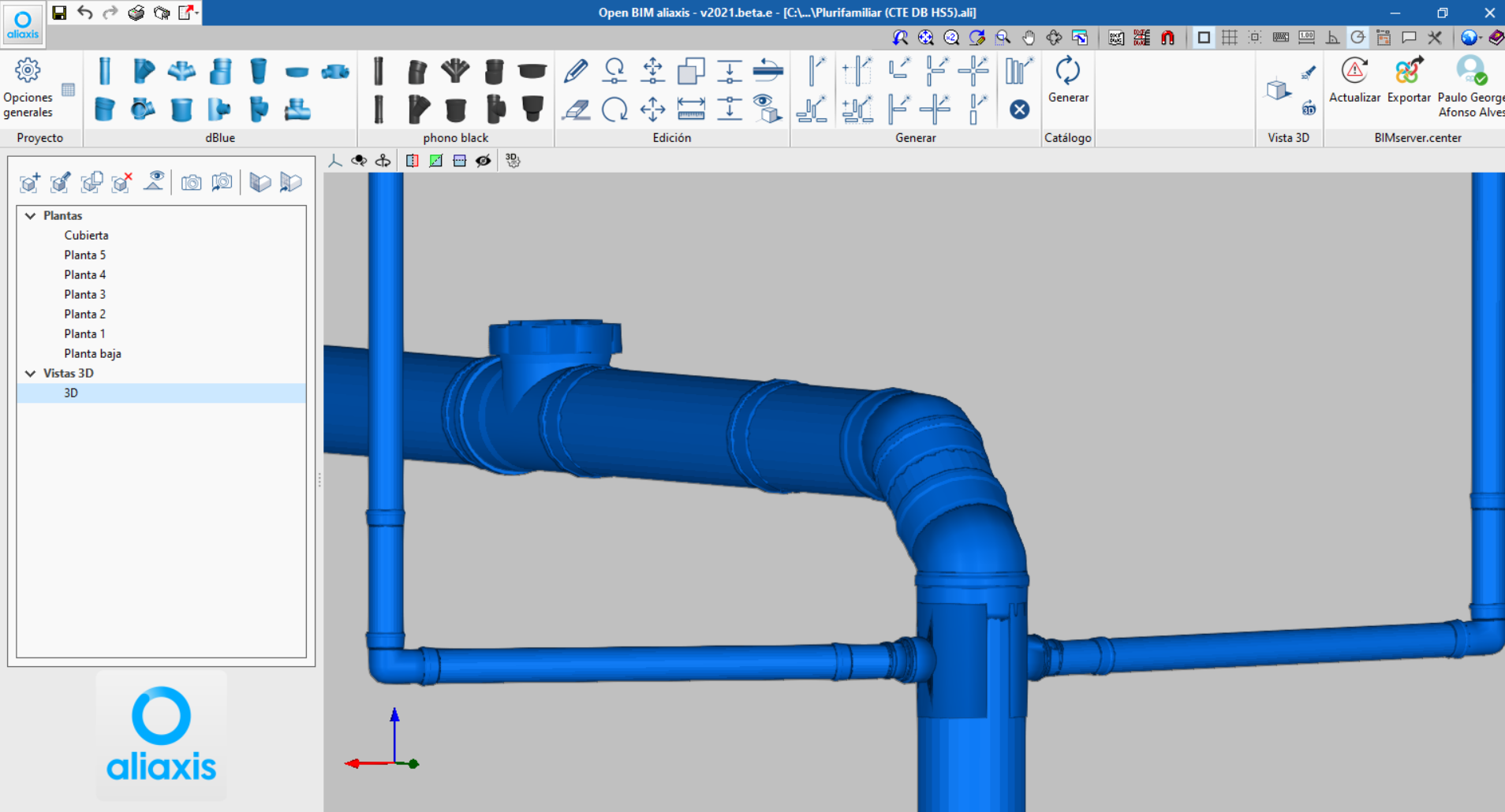
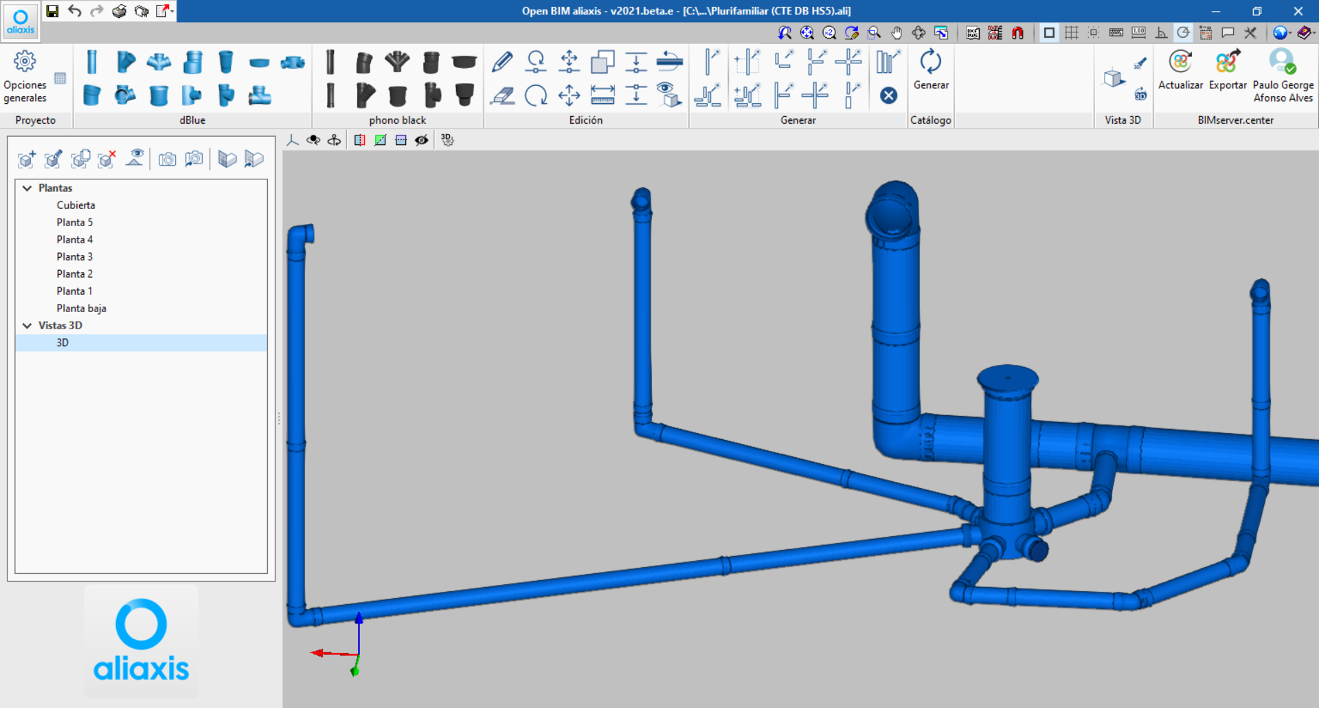
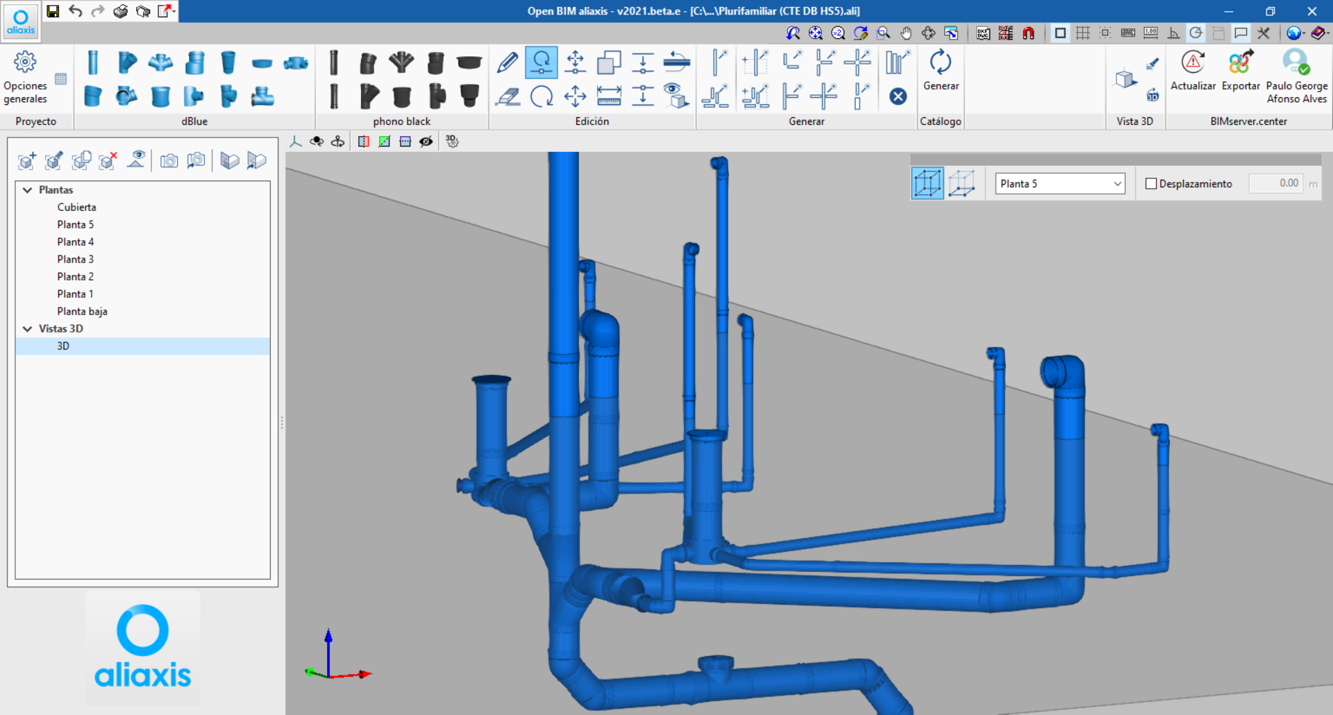
Open BIM aliaxis
New accessories from the dBlue and phonoblack catalogue
In the 2021.e version the following accessories are included from the Aliaxis dBlue and phonoblack catalogue:
- Slip couplings
- Cleanout branches
- Drainpipe terminals
- Plugs
- Floor traps
- Technical sleeves
Although the program can be installed in several languages, at the moment the included "aliaxis" catalogues are only valid for use in Spain.
Code implementation and improvements in its application
Loads on structures. Seismic loads
GBDS-2020 (Bolivia)
"Guía Boliviana de Diseño Sísmico 2020".
Implemented in CYPECAD and CYPE 3D.
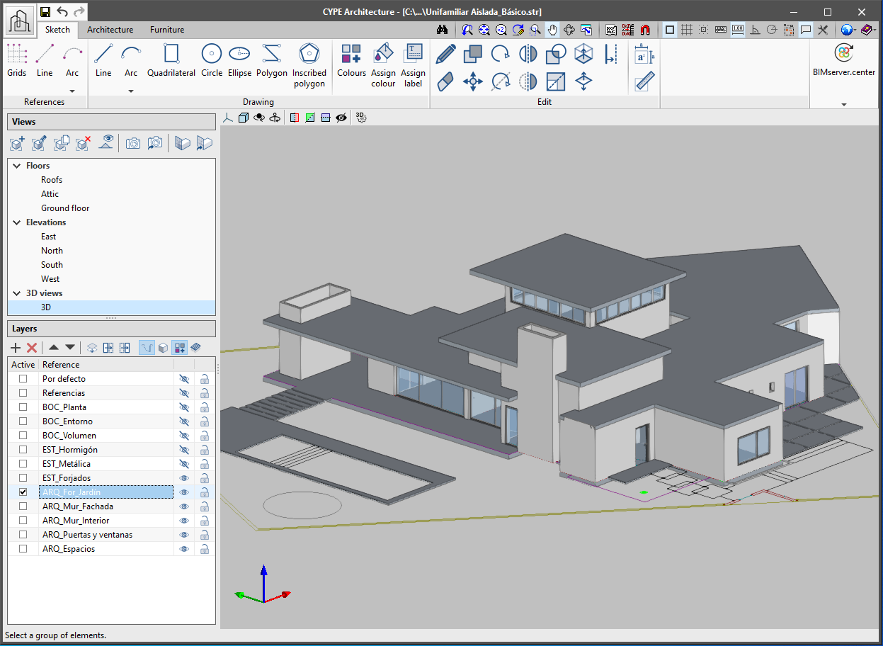
CYPE Architecture
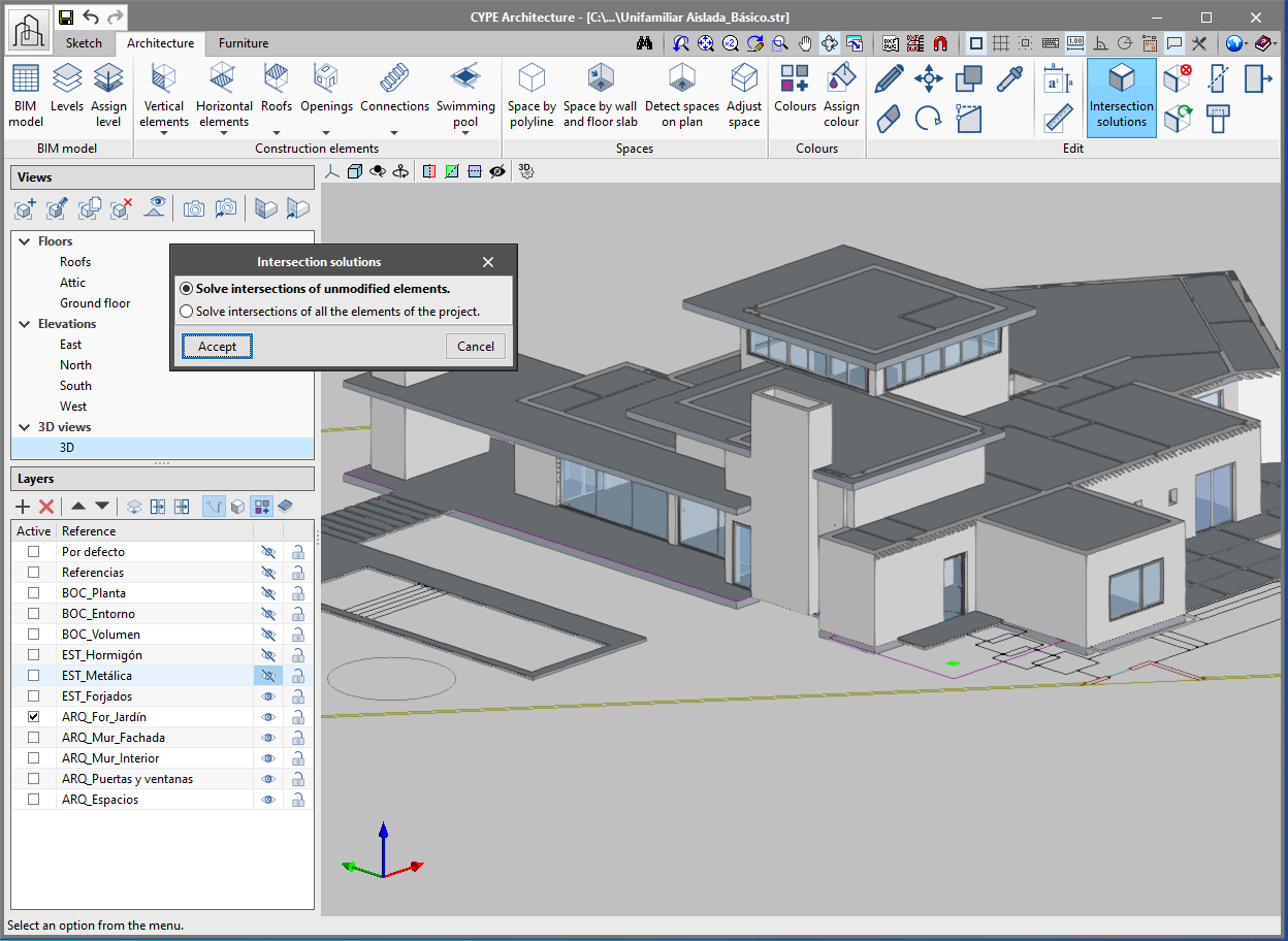
Intersection solutions
Intersection solutions allow all the intersections in the job to be easily solved (walls with walls and walls with floor slabs), either manually or automatically.
When modelling walls and floor slabs in CYPE Architecture, the intersections are not solved at the same moment as they are inserted. It is later on, when the building model has been introduced, when these intersections can be solved, either automatically or manually. To do this, there is a section for intersection solutions in the "Edit" group of the toolbar:
- Automatic intersection solutions
Allows all the intersections in the job to be automatically solved. If clicking on the "Intersection solutions" button, a panel appears that allows users to choose between "Solve intersections of all elements of the project" or "Solve intersections of unmodified elements".
If it is the first time that the user is dealing with intersection solutions in a certain project, the "Solve intersections of all elements of the project" option must be chosen.
If users have previously solved some intersections before and they do not wish for these intersections to be lost, the "Solve intersections of unmodified elements" option must be chosen.
- Manual intersection solutions
The tools for manually solving intersections allow the user to solve intersections that have not been automatically generated. These tools are:
- Cut by plane
Allow walls, floor slabs, columns and beams to be cut by a certain plane in order to solve an intersection. To do this, a section plane must be defined and the elements on which it will act must be selected:
- Click on the "Cut by plane" button.
- Define the section plane. A plane from one of the faces of the architectural elements can be chosen, or draw it manually.
- The defined plane will be drawn on the screen with a green arrow. The direction of the arrow indicates the part of the element that will be cut by the plane and that will remain, whilst the opposite side of the arrow indicates the part of the element that will be cut and deleted.
- Finally, choose the element or elements to be cut using the defined plane.
- Extend face
Allows the face of a particular element to be extended in order to solve an intersection. The steps to follow are:
- Click on the "Extend face" button.
- Choose the face of the element to be extended.
- Extend it to the other element or a fixed distance using the "allows for dimensions to be defined upon introducing each element" button.
- Subtract
Allows two elements to be subtracted whilst maintaining both parts. For example, an intersection in the meeting of two walls in which one of them is uninterrupted. The steps to follow are:
- Click on the "Subtract" button.
- Choose the element that will be cut.
- Choose the element that will be continuous.
- Delete
Allows users to delete part of an element that has been divided in two by subtraction. - Regenerate
Allows an element to be regenerated and returned to its original state.
- Cut by plane
New space generation
The "Spaces" section of the toolbar has been expanded and has new tools: "Space by wall and floor slab", "Detect spaces on plan" and "Adjust space". These new features provide greater agility when defining the spaces of the building.
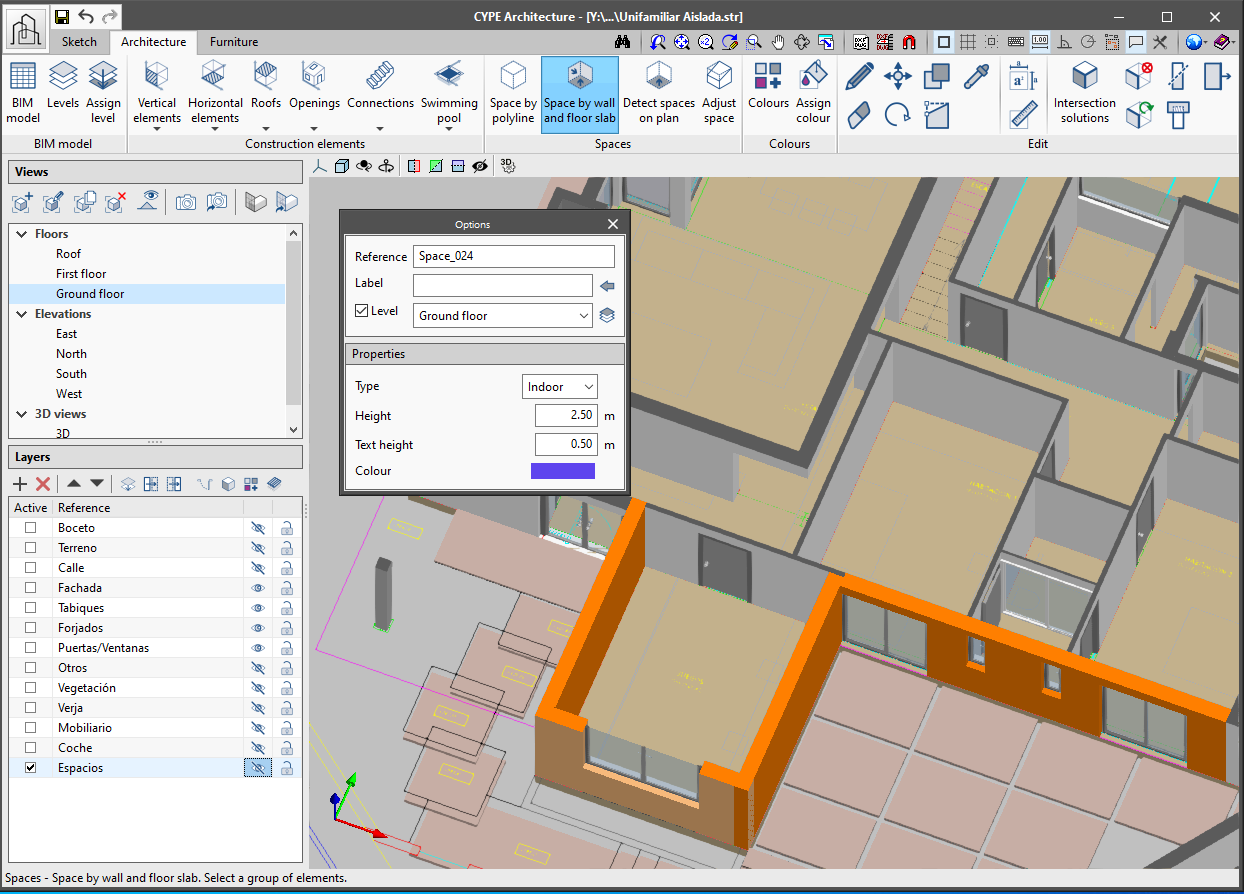
- Space by wall and floor slab
Allows a space to be generated by selecting the surrounding walls and the lower slab that contains it. The steps to follow are:
- Click on the "Space by wall and floor slab" button.
- In the options panel that appears on the left side of the viewer choose the reference, label and level. Remember that it is important to fill in these fields so that the model can be correctly read in the rest of the Open BIM workflow programs.
- Choose the properties of the space that will be created: type (indoor or outdoor), height, colour and size of the space’s text label.
- Once all the options have been defined, choose all the walls surrounding the space and right click the mouse.
- Choose the floor slab that defines the bottom face of the space. The space will be automatically generated.
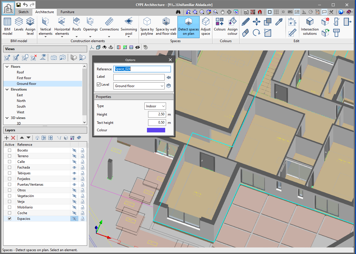
- Detect spaces on plan
Allows a space to be automatically generated when it is located in plan view. The steps to follow are:
- Go to a plan view and click on the "Detect spaces on plan" button. If this button is clicked whilst drawing in any other type of view (3D, elevation, section, etc), it will warn the user that this feature is only available for plan views.
- In the options panel that appears on the left of the viewer choose: the reference, label and level. Remember that it is important to fill in these fields so that the model can be correctly read in the rest of the Open BIM workflow programs.
- Choose the properties of the space that will be created: type (indoor or outdoor), height, colour and size of the space’s text label.
- Once all of the options have been defined, move the mouse cursor over the space to be generated. The spaces that are detected will be highlighted on the plan.
- Click on the space to be generated.
- Space by polyline
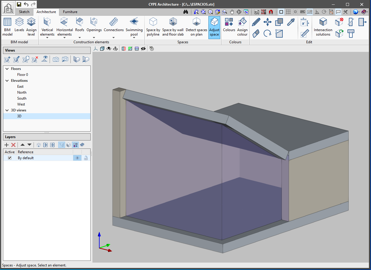
This feature already existed in previous versions of CYPE Architecture. To draw a space by polyline, indicate on screen, one by one, the perimeter points that make up the space. - Adjust space
Allows the spaces of the roofs and sloped walls to be adjusted. This feature is automatic - click on the space to be adjusted and it will adapt to be contained between the surrounding walls and floor slabs.
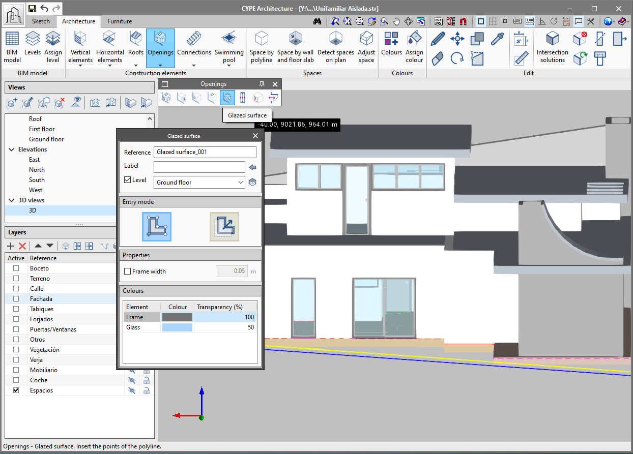
New glazed surface button
In the "Openings" section of the architecture tab a "glazed surface" function has been implemented, which allows a glass surface that is not strictly square or circular to be constructed and then read in analysis programs. Two ways of creating glazed surfaces have been included: "By points" and "Per surface area".
- By points
Draw the desired surface on the wall or floor slab by clicking one by one on the screen the perimeter points that define it. If desired, a frame can be added to the glazed surface. - Per surface area
Clicking on a sketch surface converts it into a glazed surface.
Export to IFC of new quantities sets
As of the 2021.e version, CYPE Architecture includes in the IFC file of the BIMserver.center project the following quantities sets for their corresponding IFC entities:
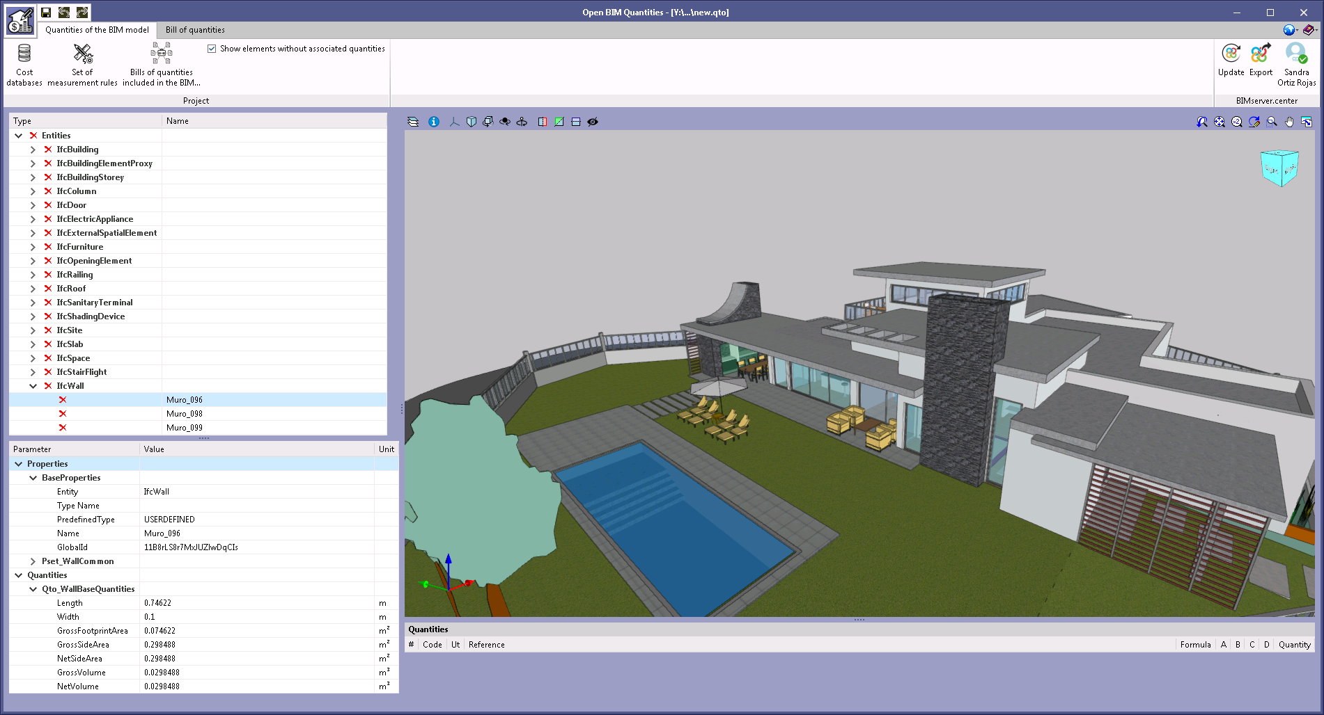
- Stairs ("Qto_StairFlightBaseQuantities")
- Length ("Length")
- Gross volume ("GrossVolume")
- Net volume ("NetVolume")
- Ramps ("Qto_RampFlightBaseQuantities")
- Length ("Length")
- Width ("Width")
- Gross area ("GrossArea")
- Net area ("NetArea")
- Gross volume ("GrossVolume")
- Net volume ("NetVolume")
- Beams ("Qto_BeamBaseQuantities")
- Length ("Length")
- Cross section area ("CrossSectionArea")
- Outer surface area ("OuterSurfaceArea")
- Gross surface area ("GrossSurfaceArea")
- Net surface area ("NetSurfaceArea")
- Gross volume ("GrossVolume")
- Net volume ("NetVolume")
- Barandillas ("Qto_RailingBaseQuantities")
- Length ("Length")
- Length ("Length")
These new quantities can be used in the Open BIM Quantities application to generate the bill of quantities of the architectural model.
Improved area measurement
The "Measure area" function in the "Edit" panel warns the user, by drawing the measurements in red, that it is not possible to measure the drawn area. The colour changes to pink when the measurement can be carried out correctly. It also allows users to dimension the perimeter of the surface being measured.
Improved wall and floor slab introduction
The introduction of walls and floor slabs is made easier. Now it is possible to view the plan where the wall and floor slab are being introduced.
XZ axis rotation in the Architecture tab
A rotate button has been included in the Architecture tab. This rotation is carried out on the XZ axis of the workplane.
Choosing the height of the drain in slope formation
As of the 2021.e version, the height of the drain can be chosen in the slope formation.
Height of louvres and curtain walls
The possibility of choosing a fixed height for louvres and curtain walls is included, which is especially useful when drawing them in floor view.
Open BIM Layout
Text optimisation
A new text rendering engine has been implemented and text handling optimisations have been included in its management.
3D scenes with transparent background
A transparent background can be defined for scene views. This property will remain unchanged, so that scene views with a transparent background can be printed and exported to all formats.
Support for png files
The program allows png files to be imported using the external file library.
CYPECAD and CYPE 3D
Features of the "Advanced design of surface foundations" module
The "Advanced design of surface foundations" module is common to CYPE 3D and CYPECAD. Nevertheless, the features of this module are different in each program:
- In CYPECAD
Allows users to design foundations with footings or pile caps with special intersections (intersections between strap and tie beams), establish polygonal limits for footings and enter line, point and surface loads on footings, pile caps, and strap and tie beams.
By being able to consider point, line and surface loads on the foundation elements, users can consider the effects of the load of the soil, screeds, façades, stairs etc. acting on the elements and take into account any possible favourable effect they may have on their equilibrium and size. - In CYPE 3D
Users can only place polygonal limits on footings.
As of the 2021.e version, so users who have this module in their license can use all of its features, those who have CYPE 3D in their license but not CYPECAD, can also use CYPECAD (2021.e version) and import a CYPE 3D project to design the foundation using all the tools the "Advanced design of surface foundations" module has in CYPECAD.
CYPECAD
Customisable reports
The following predefined reports can be added optionally as chapters in customisable reports:
- Composite slab quantities.
- Floor slab reinforcement.
- Surface areas/Volumes.
- Horizontal wind loads.
Foundation element checks
The checks the program performs on foundation elements are displayed in a more compact manner, as occurs with checks of other types of elements.
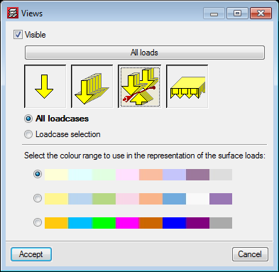
More colour palettes to represent surface loads
Two colour palettes have been added to view surface loads.
Other improvements and corrections
The 2021.e version of CYPECAD also includes the following improvements (some of which correct possible problems that may arise under specific circumstances):
- Import PDF files as drawing templates
These templates work in the same way as those that have been created based on images, and so, it is not possible to snap to any objects on them. - "Tributary widths" panel
The "Tributary widths" panel has been improved to better view the names of the floors and corresponding values. - "Drawing editor – 3D structure" panel
The "Drawing editor – 3D structure" panel has been improved and users can now view the complete name of the 3D structures. - "Column details" drawing
The generation of the "Column details" drawing has been improved when the "By floors" option is selected. In some cases, the drawing of all the columns was not obtained. - Castellated beams
The view of castellated beams has been improved in the 3D view of the project. Now, the number and position of the openings, coincide with those drawn in the frame drawings. - Representation of castellated beams on frame drawings
An error that occurred when representing castellated beams on frame drawings has been solved. This error occurred only if the number of infilled openings at the beginning was different to that at the end, and under specific circumstances. - Column references
An error has been solved that occurred when column references were drawn when a column was defined on another that had an outline with more than 4 sides. - Import columns in the BIM model
An error has been solved that occurred when columns were imported from the BIM model when the selected concrete code was the REBAP code. - Walls
An error has been solved that occurred when the analysis was launched of a project containing walls that had been defined on one floor, with a strip footing and its top part ended with a sloped plane. - Deformed shape
An error has been solved that occurred when users consulted the deformed shape in specific cases.
CYPE 3D
Keyboard shortcuts
Keyboard shortcuts have been added to make some of the most frequently used tools easier to use:
- Ctrl + m: Tools > Move elements
- Ctrl + c: Tools > Copy elements
- Ctrl + b: Bar > New
- Ctrl + d: Bar > Discover
- Ctrl + p: Bar > Buckling
- Ctrl + e: Bar > Pin ends
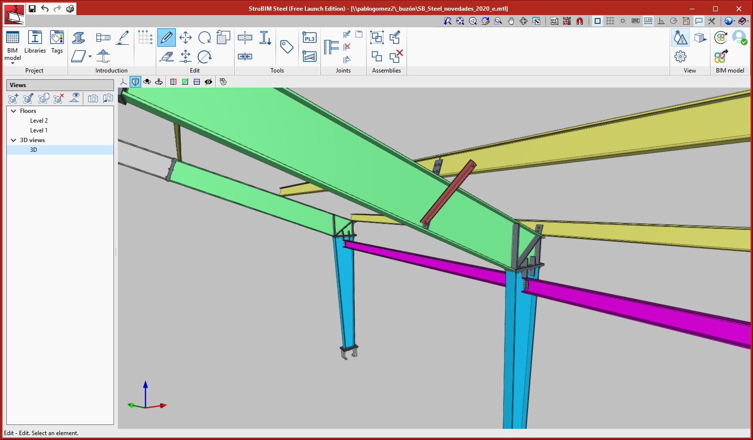
StruBIM Steel
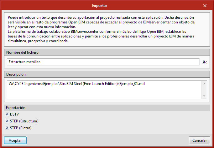
Export in STEP format
As of the 2021.e version, it is possible to export the model in STEP format. The options to export the complete structure (Structure) or specific assemblies (Assemblies) have been implemented in the dialogue where users can select to export the model to the BIMserver.center platform. This export section also includes the option to export in DSTV format.
Using the STEP format (ISO 10303), users can exchange data between design and manufacturing systems (CAD, CAM, CAE).
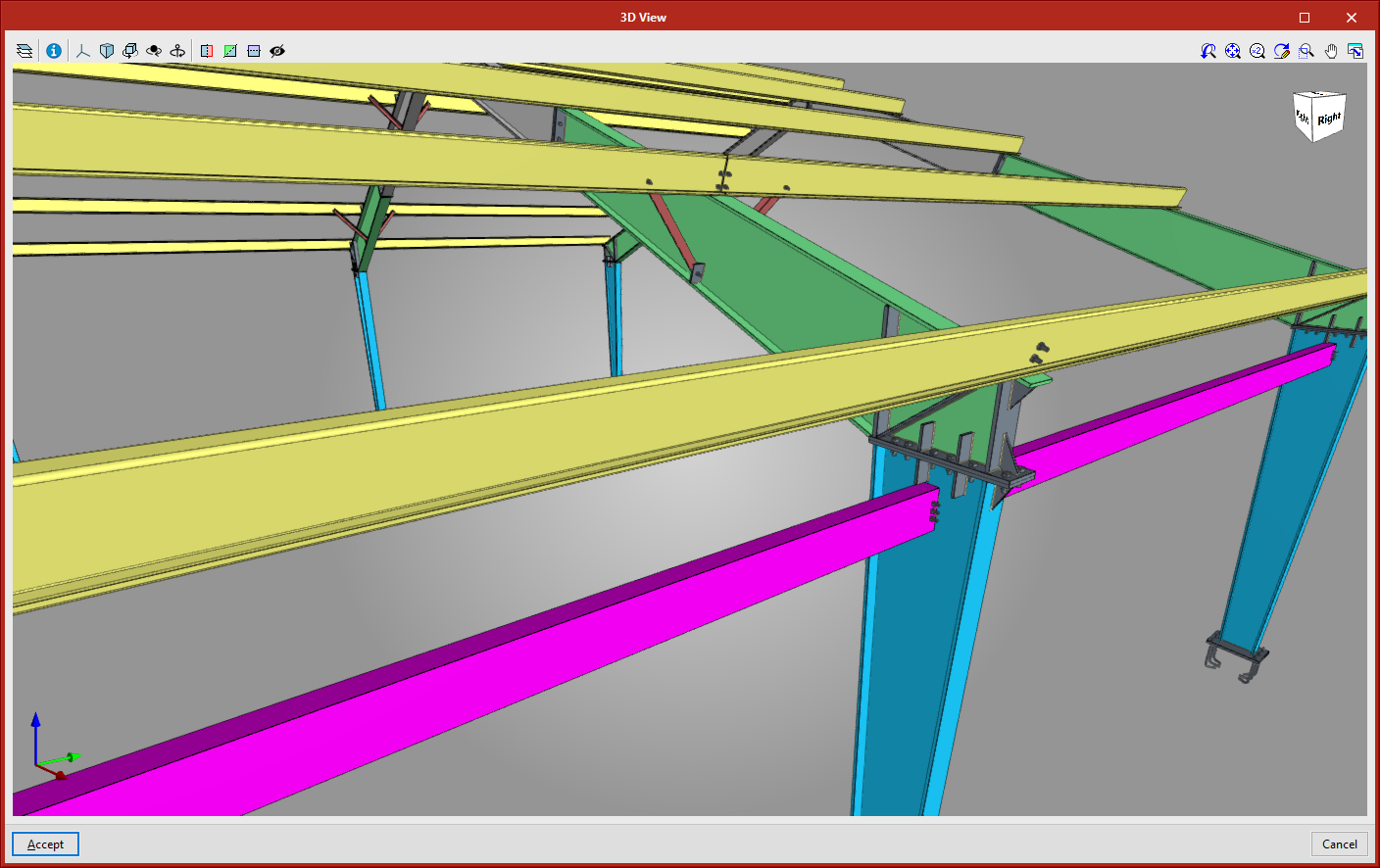
New types of connections
- Connection between continuous beams with different depths
This connection can be found in the Beam-Beam category.
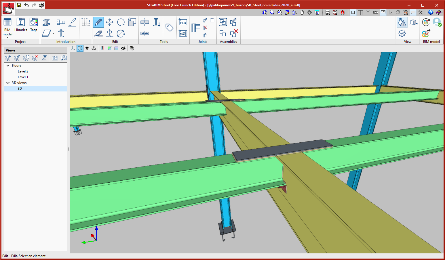
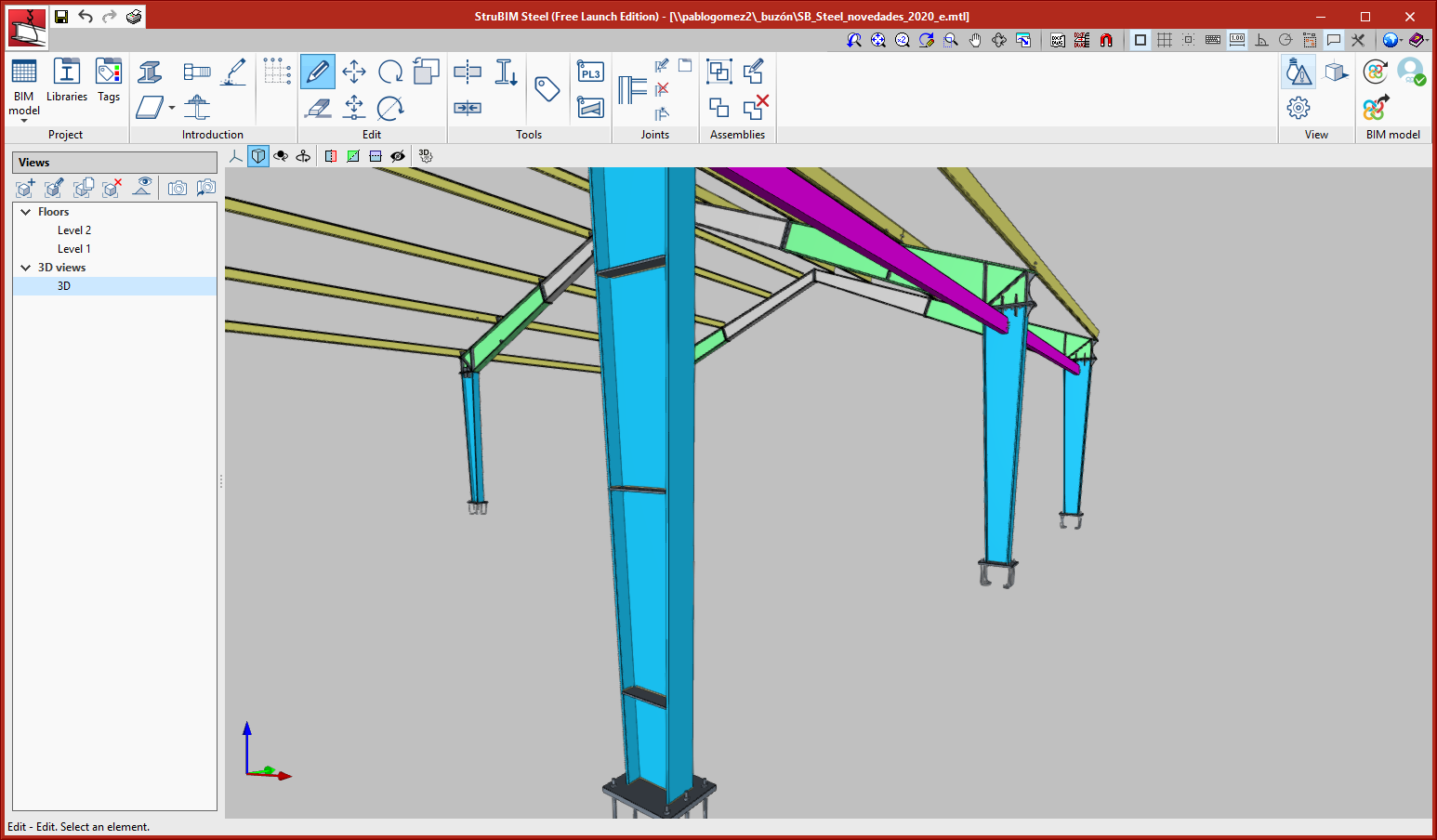
- Web stiffeners, distributed along I-sections
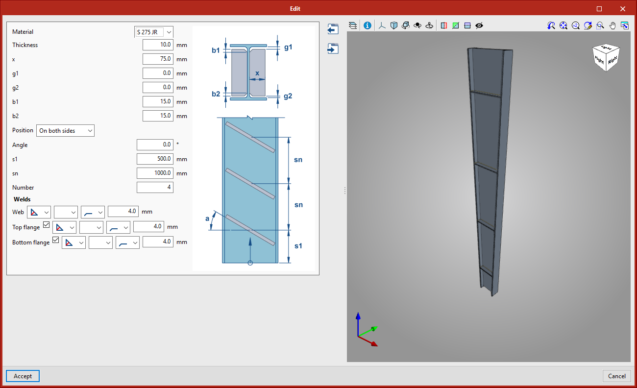
- Hollow section connection
This connection can be found in the new "Hollow sections" connections category; it consists of a welded connection between two circular hollow sections.
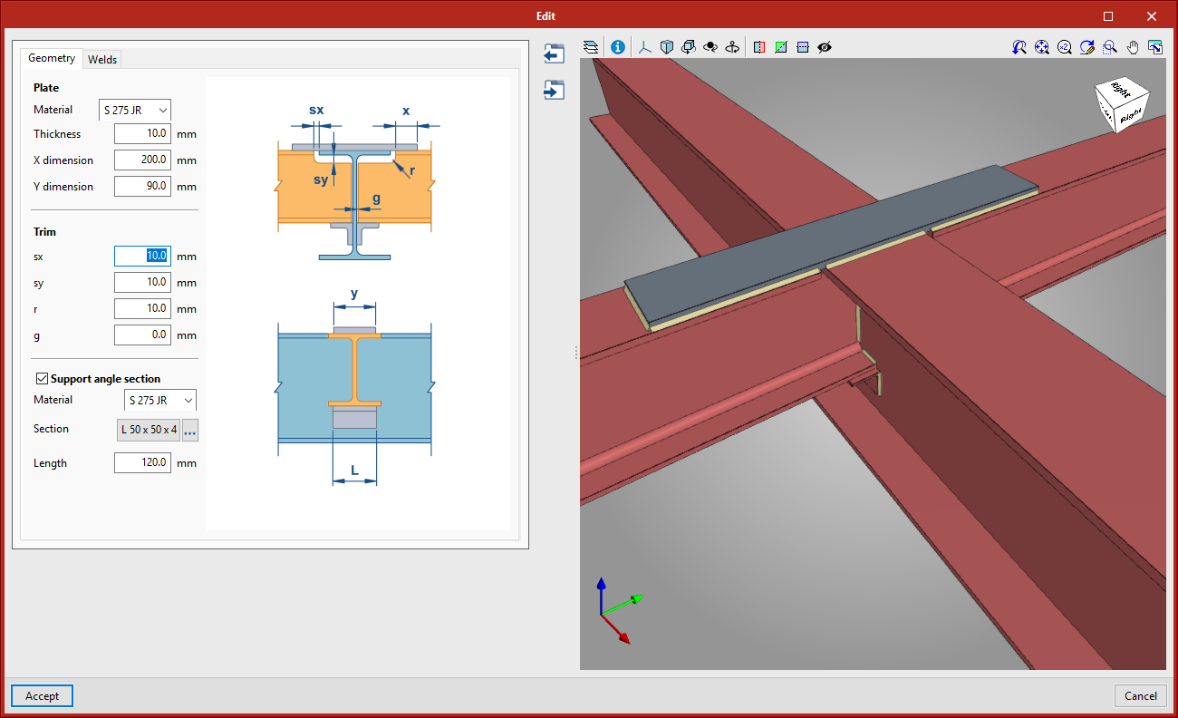
Connection adaptations for reinforced sections with variable depth
Some of the existing connections have been adapted so they can be used with reinforced sections with variable depth. The connections that have been adapted in this version are:
- Secondary section pinned connection
- Main section to purlin connection
- Main section to two purlin connection
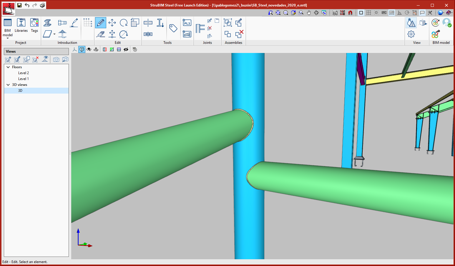
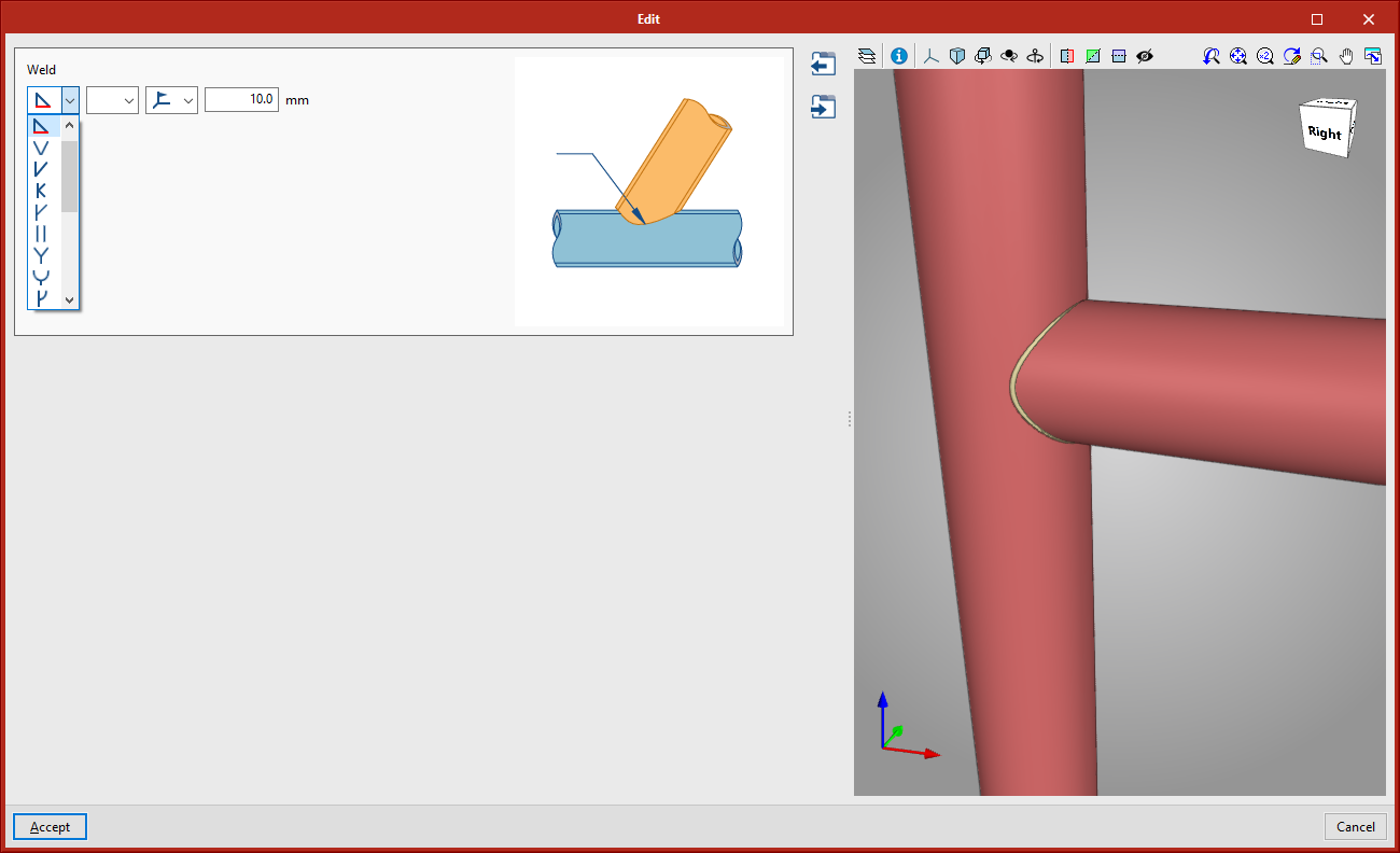
New types of welds
More types of welds are now available. The new types are:
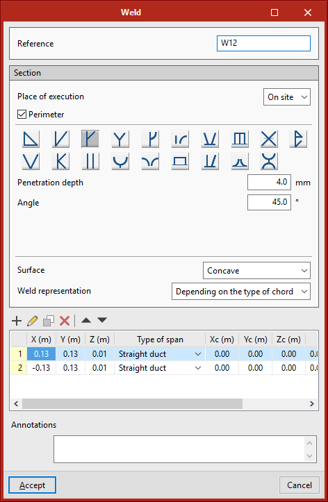
 Single V butt weld with wide root face
 Single U butt weld
 Single J butt weld
 Double rounded bevel weld
 Rounded bevel weld
 Plug weld
 Single V butt weld with steep flanks
 Single bevel butt weld with steep flanks
 Edge weld
 Flanged butt weld
 Double V butt weld
 Double U butt weld
 Combined single bevel and fillet butt weld
StruBIM Shear Walls
Available installation languages
As of the 2021.e version, StruBIM Shear Walls can be installed in Catalan, English, French, Italian, Portuguese and Spanish. In previous versions, the program could only be installed in English and Spanish.
Code implementation
The following Eurocode checks have been implemented in the 2021.e version of StruBIM Shear Walls:
- Concrete structures (Eurocode 2)
- EN 1992-1 (UE)
- EN 1992-1 (Bulgaria)
- NF EN 1992-1 (France)
- NP EN 1992-1 (Portugal)
- SR EN 1992-1 (Romania)
- MS EN 1992-1 (Malaysia)
- SS EN 1992-1 (Singapore)
- UNE-EN 1992-1 (Spain)
- Loads on structures. Seismic action (Eurocode 8)
- EN 1998-1 (EU)
- EN 1998-1 (Bulgaria)
- NF EN 1998-1 (France)
- NP EN 1998-1 (Portugal)
- EN 1998-1 (Romania)
- MS EN 1998-1 (Malaysia)
- SS EN 1998-1 (Singapore)
- UNE-EN 1998-1 (Spain)
Other improvements and corrections
The 2021.e version of StruBIM Shear Walls also includes program corrections that solve errors that could arise in specific circumstances:
- Checks for normal forces
An error has been solved, which occurred when the program checked the normal forces in shear walls with a slight rotation with respect to the X-Y axes. - Import BIM models
An error has been solved, which occurred when users tried to import a BIM model that had been generated for a later version of the program.
StruBIM Rebar
Available installation languages
As of the 2021.e version, StruBIM Rebar can be installed in Catalan, English, French, Portuguese or Spanish. In previous versions, the program could only be installed in English or Spanish.
CYPECAD MEP and IFC Builder
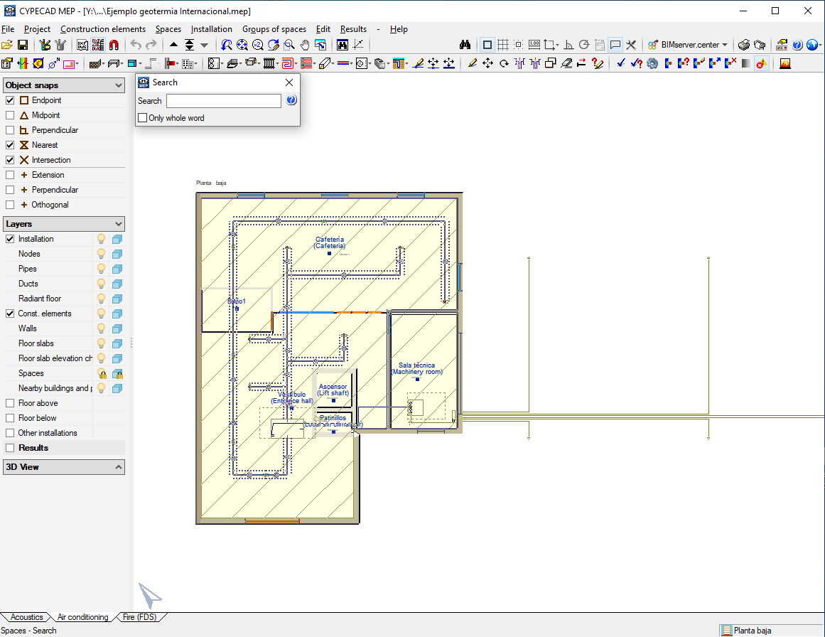
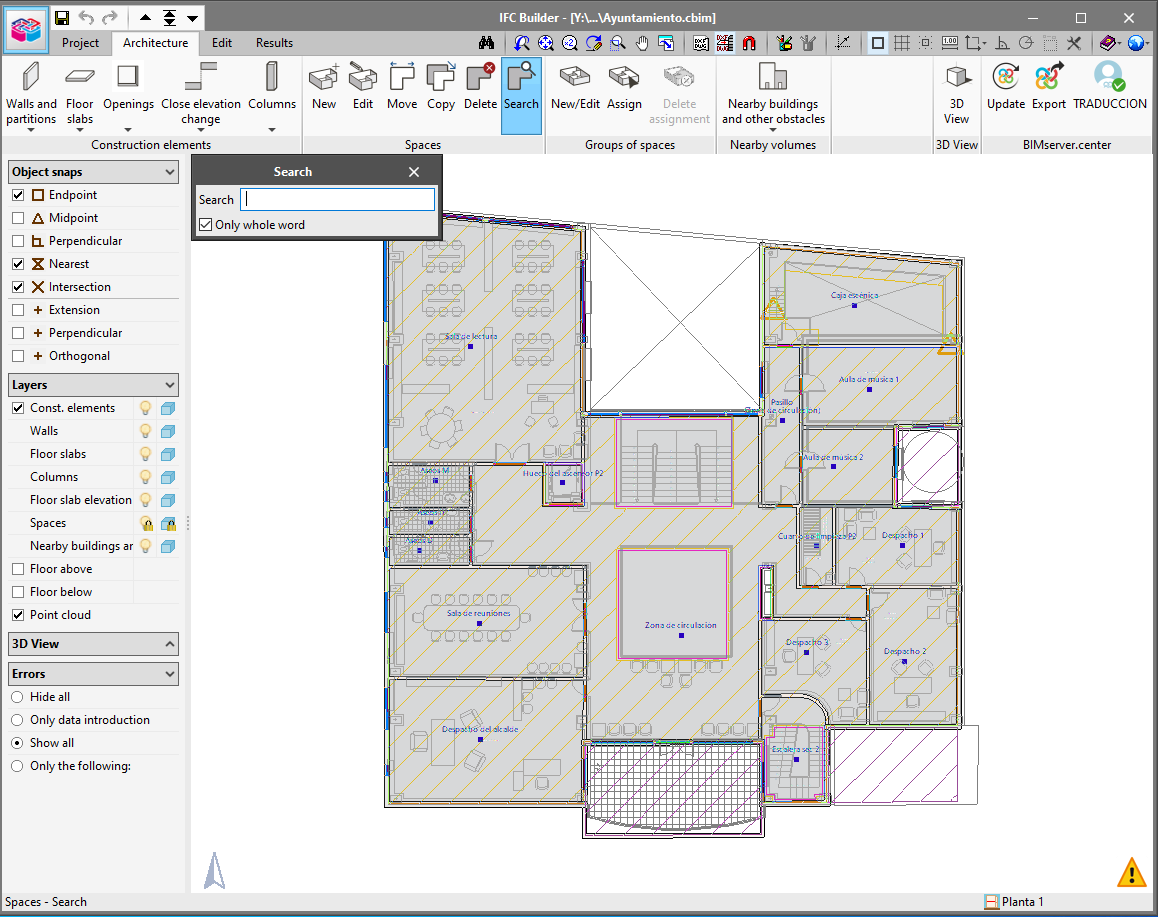
Search tool for spaces
A new tool has been added in IFC Builder (Architecture > Spaces > Search) and in CYPECAD MEP (Spaces > Search) that allows users to search for architectural spaces and mark them in the drawing area. When the tool is activated, a panel is displayed where users can write a reference. The application will highlight the names of the spaces that contain the substring entered totally or partially, depending on whether the "Only whole word" option is activated. In this way, it is easier for users to identify spaces in projects of large dimensions with a large number of spaces per floor.
CYPELEC Distribution
Import of electrical equipment from the BIM model
As of the 2021.e version, CYPELEC Distribution allows equipment with electrical load that is contained in the BIM model to be read.
In this version, the import of HVAC equipment from the following programs has been enabled:
- Open BIM DAIKIN
- Open BIM BOSCH
- Open BIM PANASONIC
There are two options for importing and incorporating this equipment into the electrical installation:
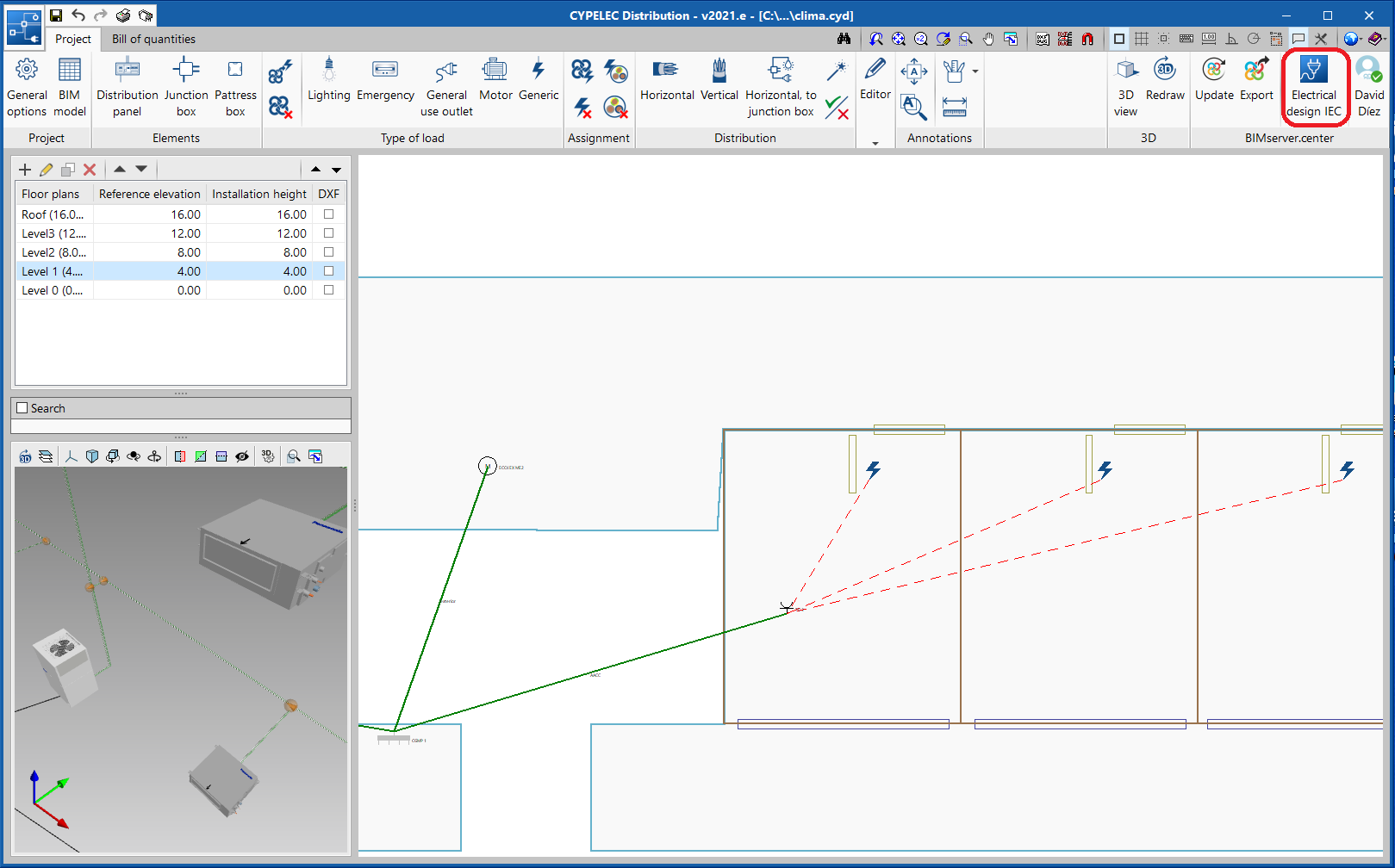
- Associate the BIM model element to a new load
To carry out this option, click on the icon in the toolbar highlighted in the attached image and select the element of the BIM model to be associated.
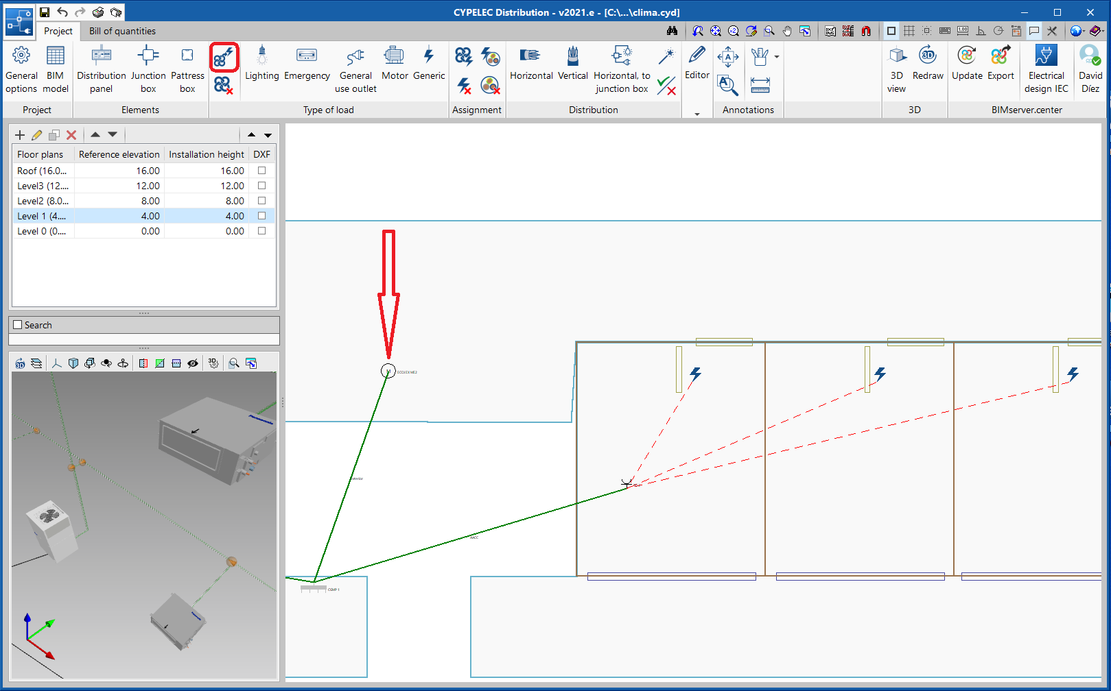
- Associate the equipment of the BIM model to a previously defined and expected load the electrical installation
To carry out this option, click on the icon in the toolbar highlighted in the attached image, indicate the equipment of the BIM model and finally select the load to which it will be associated.
In this case, the program checks that the sum of the power of the associated equipment is less than the expected power in the selected load.
CYPELEC Core, CYPELEC Distribution, CYPELEC Electrical Mechanisms
Shortcuts to other applications
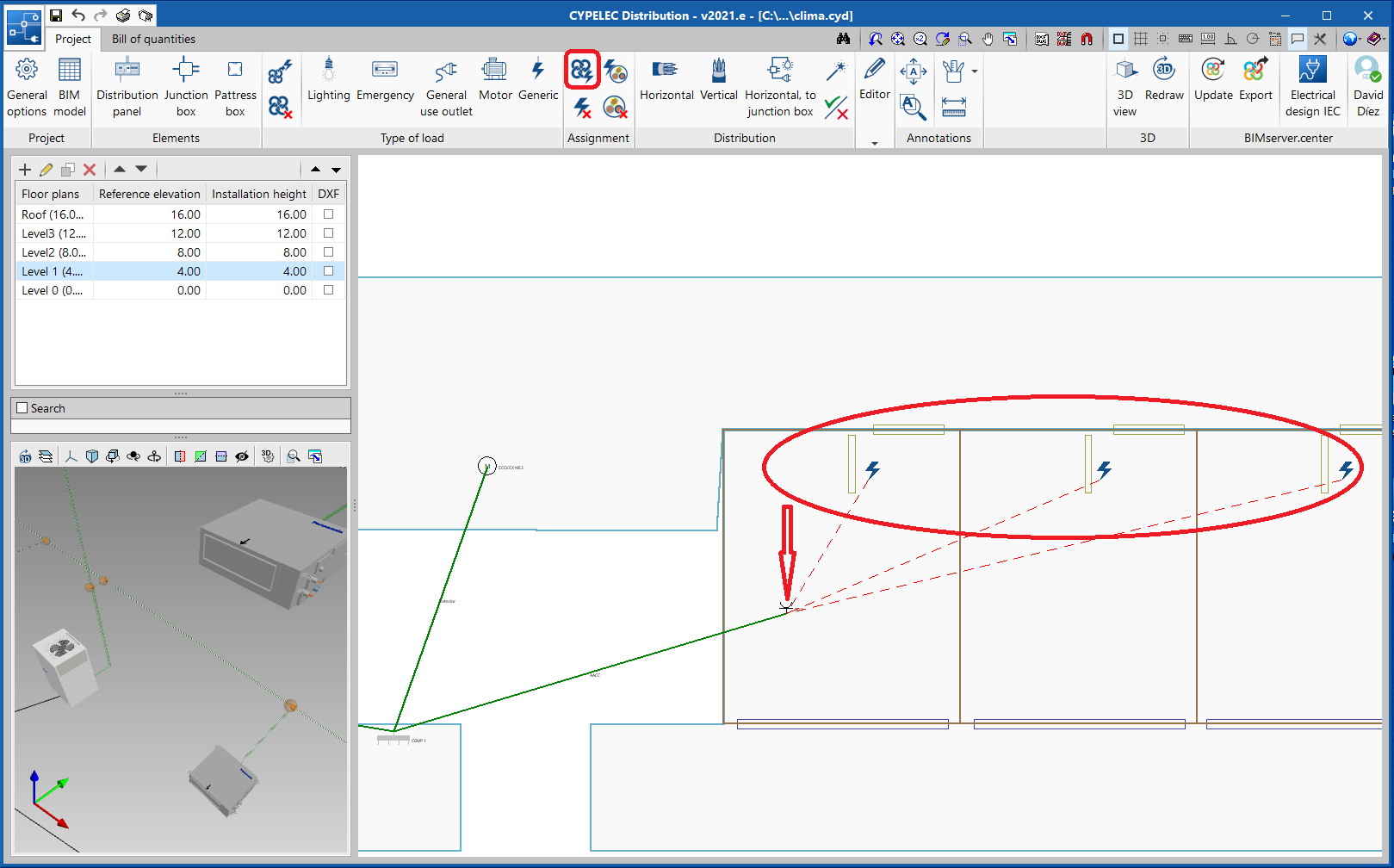
Similarly to the 2021.c version of CYPE Architecture, in this version (2021.e) shortcuts have been implemented in the the programs CYPELEC Electrical Mechanisms, CYPELEC Distribution and CYPELEC CORE, allowing other applications to be opened in order to continue with the development of the project.
Selecting these shortcuts first exports the results obtained in the user’s current program to the BIM project and then opens the selected application, which makes it quicker to continue with the development of the project.
In this way, the user will have guided assistance which will allow them to move from program to program to complete the electrical installation. A design can be carried out starting from the architectural model right through to the analysis of the low, medium and high voltage installation without having to search for the application that continues with the development of the project.
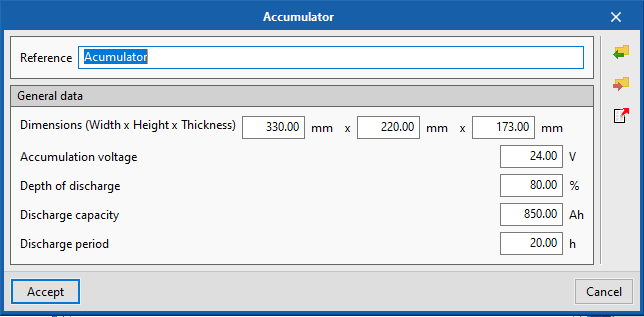
CYPELEC PV Systems
Introduction of equipment dimensions
When creating or modifying inverters, regulators or accumulators their dimensions can be entered.
CYPELEC Grounding IEC and CYPELEC Grounding IEEE
Installation in English and Portuguese
As of version 2021.e, CYPELEC Grounding IEC and CYPELEC Grounding IEEE are now available in English and Portuguese.
More information:
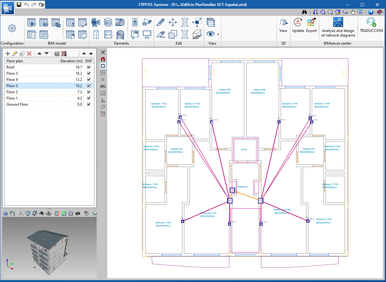
CYPETEL Systems
Direct link to CYPETEL Schematics
In the 2021.e version of CYPETEL Systems, a direct link to the CYPETEL Schematics application is included in the toolbar to continue the development of the project.
The above-mentioned link first exports the results obtained by CYPETEL Systems to the BIM project and then opens the CYPETEL Schematics application, which makes it quicker to continue with the BIM project.
CYPETEL Schematics allows for the design and analysis of telecommunication system diagrams (infrastructure, coaxial cables, optical fibre cables, etc), using the information contained in the files exported by CYPETEL Systems.
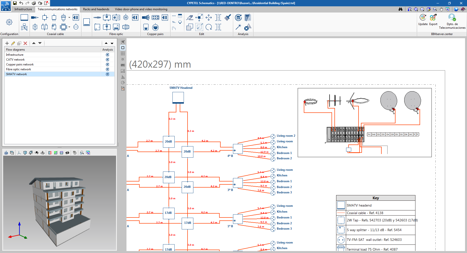
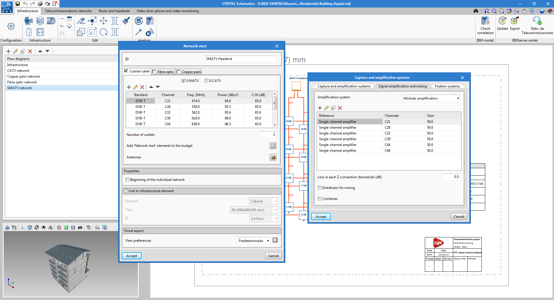
CYPETEL Schematics
New equipment for designing the headend of coaxial networks
New equipment (antenas, masts, towers, modular amplifiers, etc) has been incorporated to the "Racks and headends" tab. This equipment allows detailed diagrams of the headend of coaxial networks to be created.
In addition, the "Network start" element has a new option to define the equipment and technical data of the capture and amplification systems of the S/MATV coaxial headend.
CYPEHVAC Ductwork
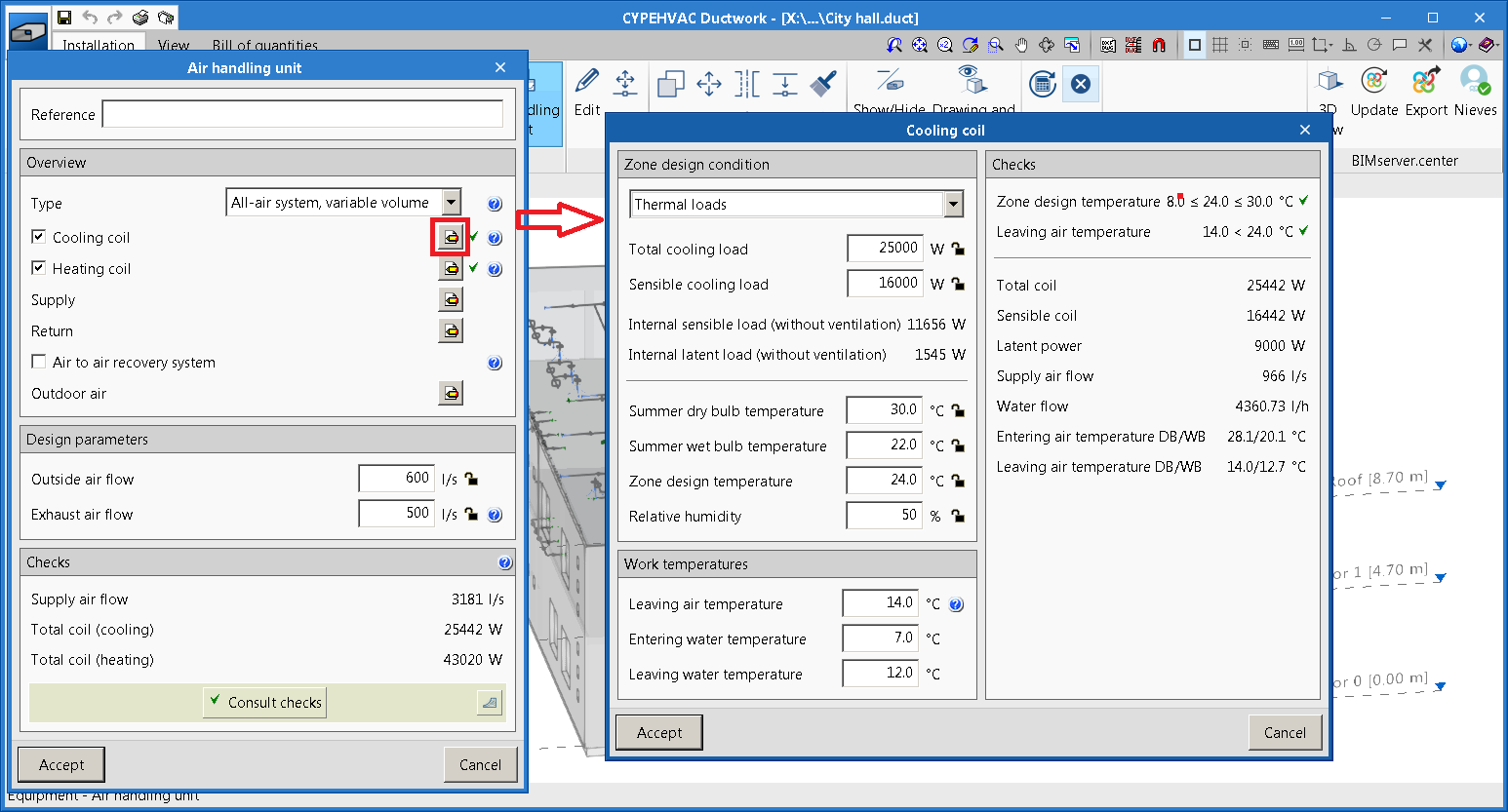
Designing AHUs from the space data
In the 2021.c version of CYPEHVAC Ductwork the ability to enter thermal loads in spaces was implemented (manually or automatically read from the BIM model).
As of the 2021.e version, this information, together with the internal design conditions of the spaces, is used to design and analyse the Air Handling Units (AHUs) present in the job.
CYPETHERM LOADS and CYPETHERM EPlus
URSA product update
Update of the thermal insulation products by the manufacturer URSA according to its 2021 catalogue.
CYPETHERM EPlus
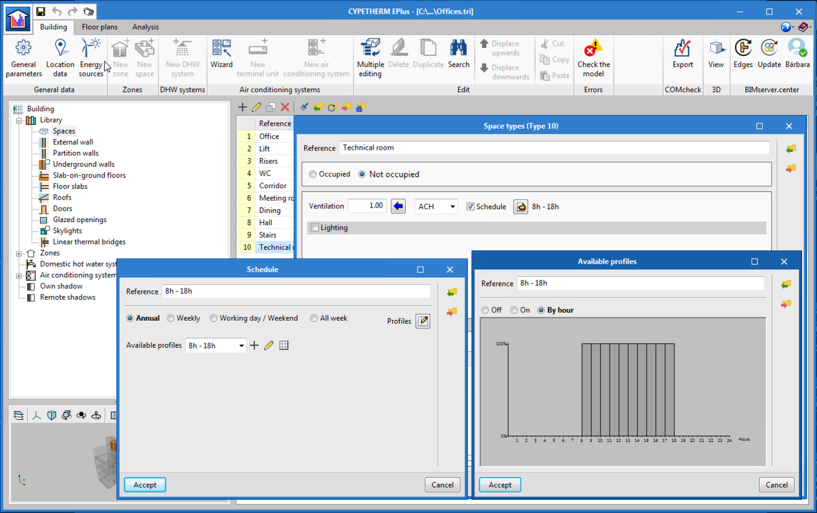
Definition of ventilation schedules in all types of spaces
The option has been added to define an hourly ventilation schedule in non-habitable spaces or those without permanent occupancy, in a similar way as is done for spaces with occupancy. Within the Library, upon defining a non-habitable space, the Schedule box can be seen in the Ventilation section, which allows users to vary the ventilation flow for each hour of the year. If this box is left unmarked, the program will consider that the indicated ventilation flow remains constant throughout the year.
Arquimedes
Bill of quantities of Revit models
Error checks in the extraction of Revit quantities
To help users minimise errors in the extraction of quantities from the BIM elements of a Revit model, a series of basic checks related to the combination of Revit parameters that are used in the extraction have been implemented. When an error is detected, both the item and the linked Revit entity are marked with the  symbol.
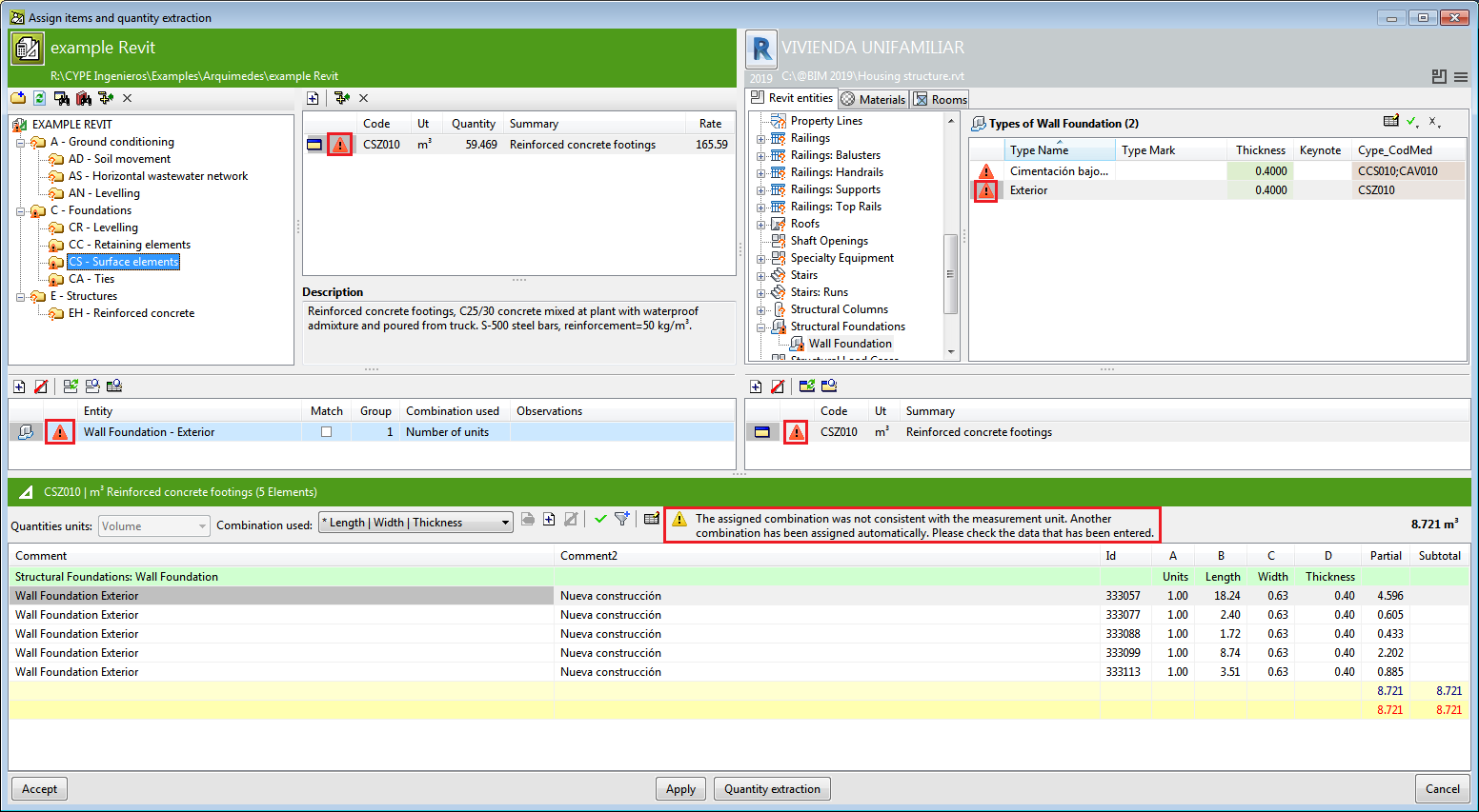
The warnings that can appear with the checks that are carried out are:
- "The assigned combination was not correct because it was already defined for another quantities unit. A different one has been assigned automatically. Please check it"
This situation is usually due to users having modified the quantities unit of the item in Arquimedes after its quantities have been extracted from Revit. In this case, Arquimedes assigns another parameter combination automatically, which users can check and approve using the button (Verify use combination for the extraction of the quantities).
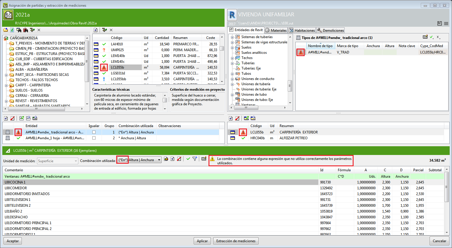
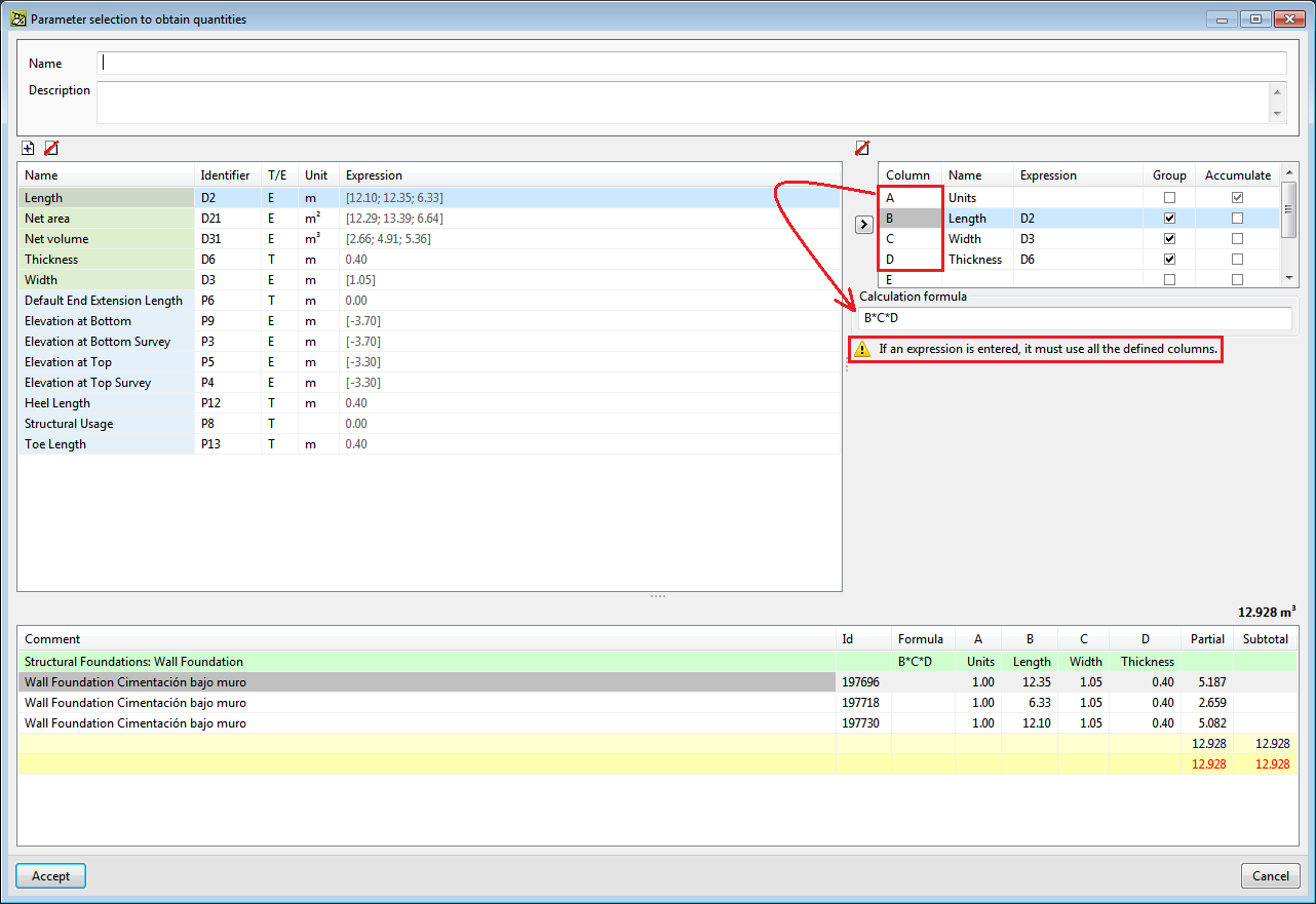
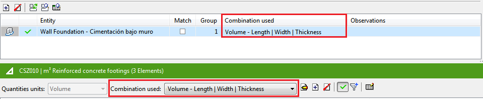
- "This combination contains an incorrect expression. Please check it"
This occurs when an expression or formula of the combination that is used to extract the quantities is incorrect. The user formula must be checked and corrected.
Most of the time, the error that has been entered in the formula is because of a missing column. In the case that is shown in the image, the error is due to column A having been entered in the expression or formula A*B*C.
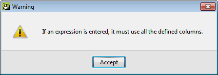
- "The calculation formula must include all the columns that have been defined or remain empty"
This can appear when the calculation formula is defined for the user combination in the quantities extraction. If the formula is incorrect, when the "Accept" button is pressed in the "Parameter selection to obtain quantities" dialogue box, the program indicates it and does not allow for the user combination to be created until it is corrected.
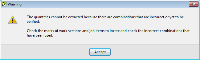
- "The quantity extraction cannot be carried out due to an incorrect combination or one that has yet to be verified"
When the "Quantity extraction" button is pressed, the program checks whether there are any incorrect combinations or any which have yet to be verified, and does not allow for the quantities to be extracted until all the incorrect combinations have been checked. These combinations are marked in work sections with the symbol and in items with so they can easily be found.
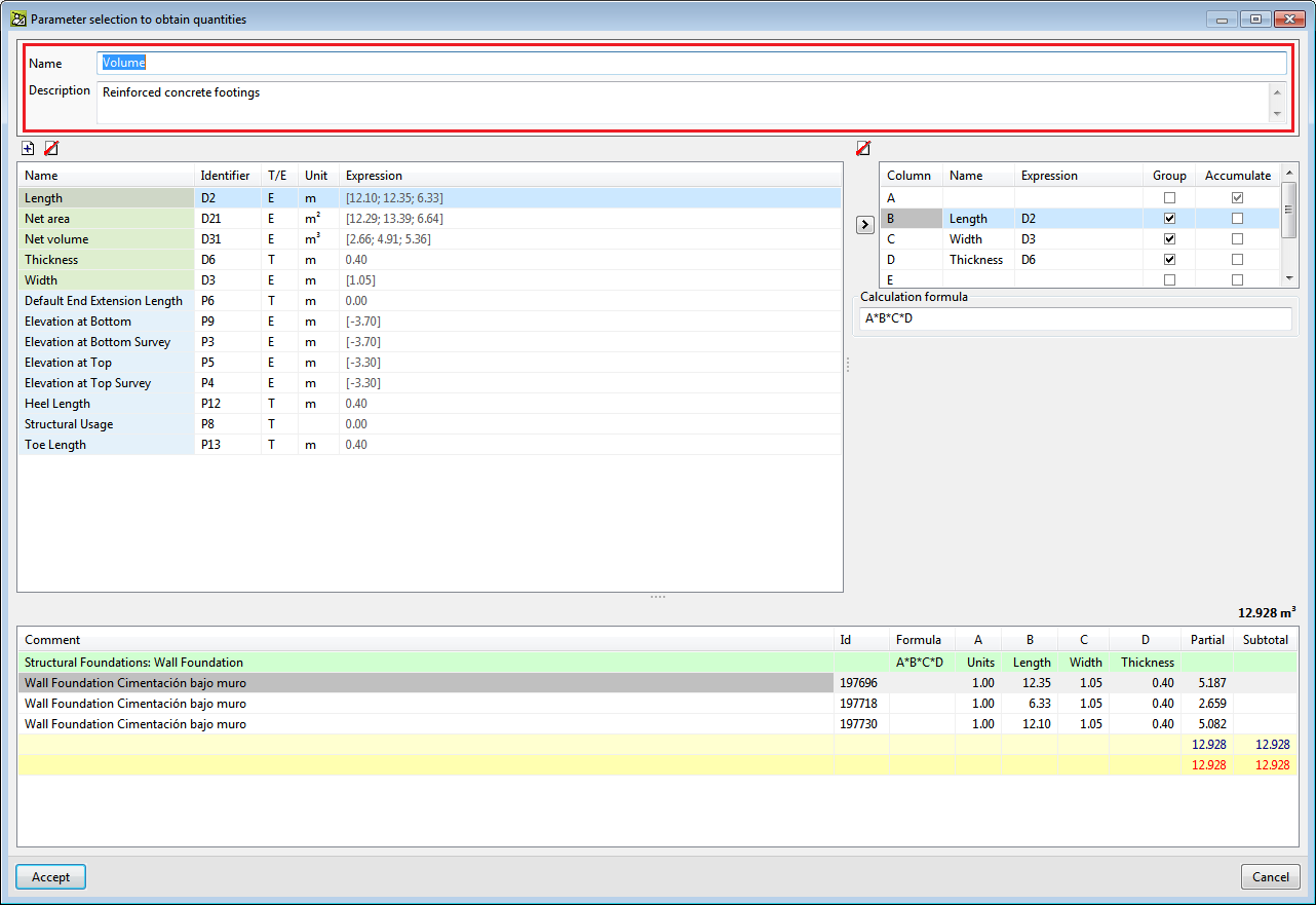
Aids to identify user combinations in quantity extractions
To help users identify the user combinations that are used in the quantity extractions, the "Name" and "Description" fields have been added in the "Parameter selection to obtain quantities" dialogue box.
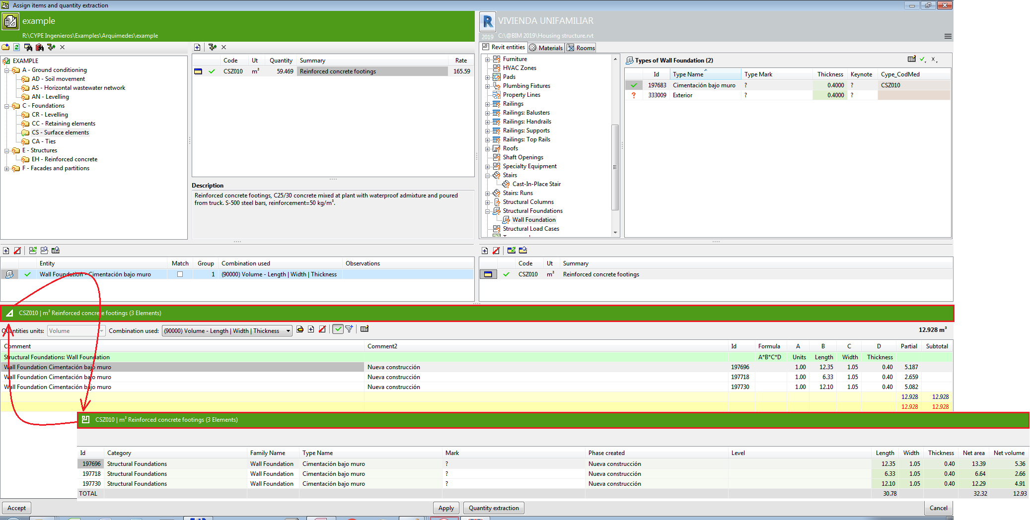
View cases of links between a Revit element and an Arquimedes item
To help users identify and check quantity details, all the cases of the existing link between the Revit element and job item that have been selected for the quantity extraction, can be displayed. The cases can be viewed in the "Assign job items and quantity extraction" dialogue box by pressing anywhere along the bar on the header of the quantity details table. By pressing again on the same bar, the quantity details are displayed.
Open BIM Quantities and applications with the Bill of Quantities tab
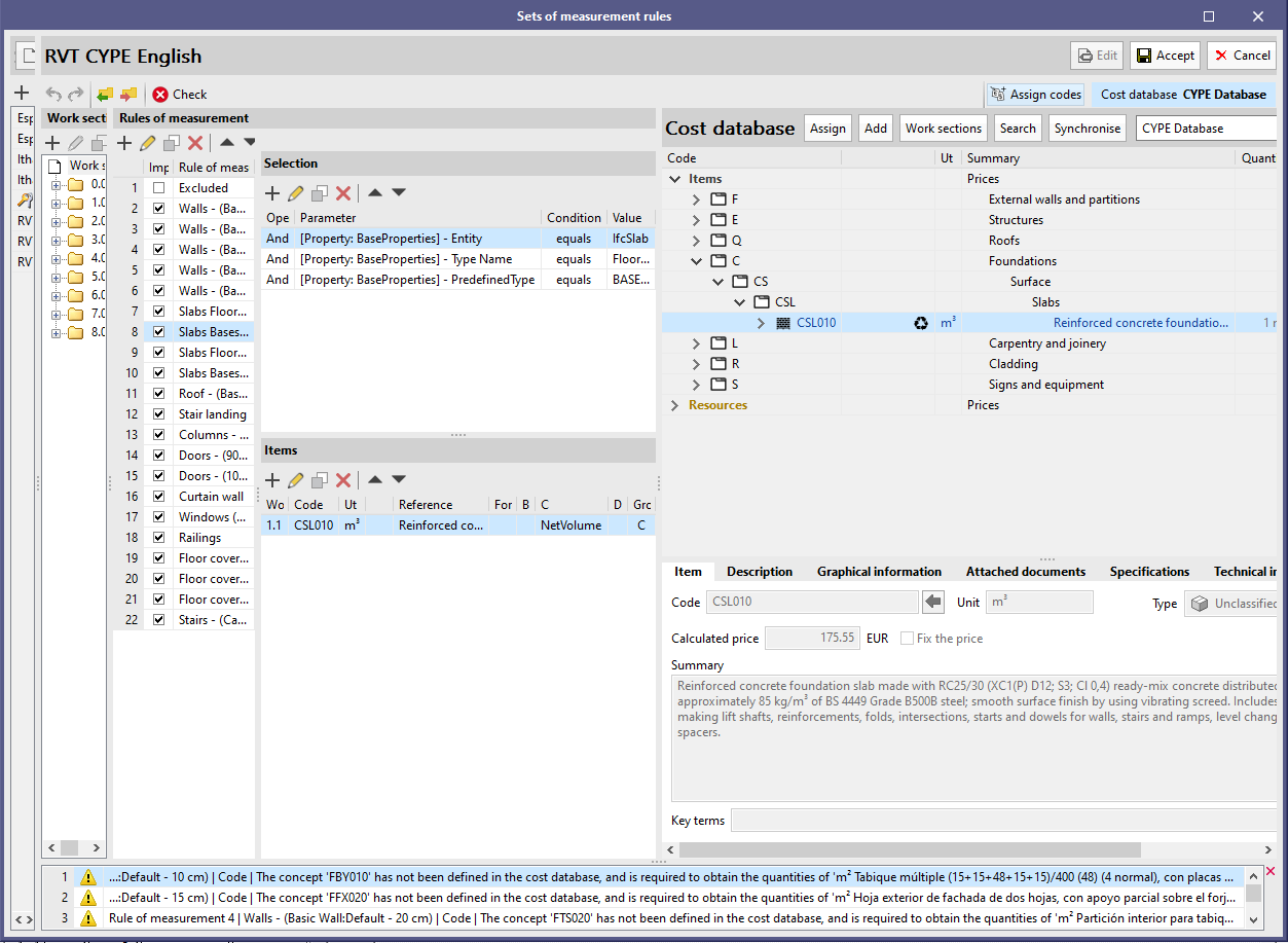
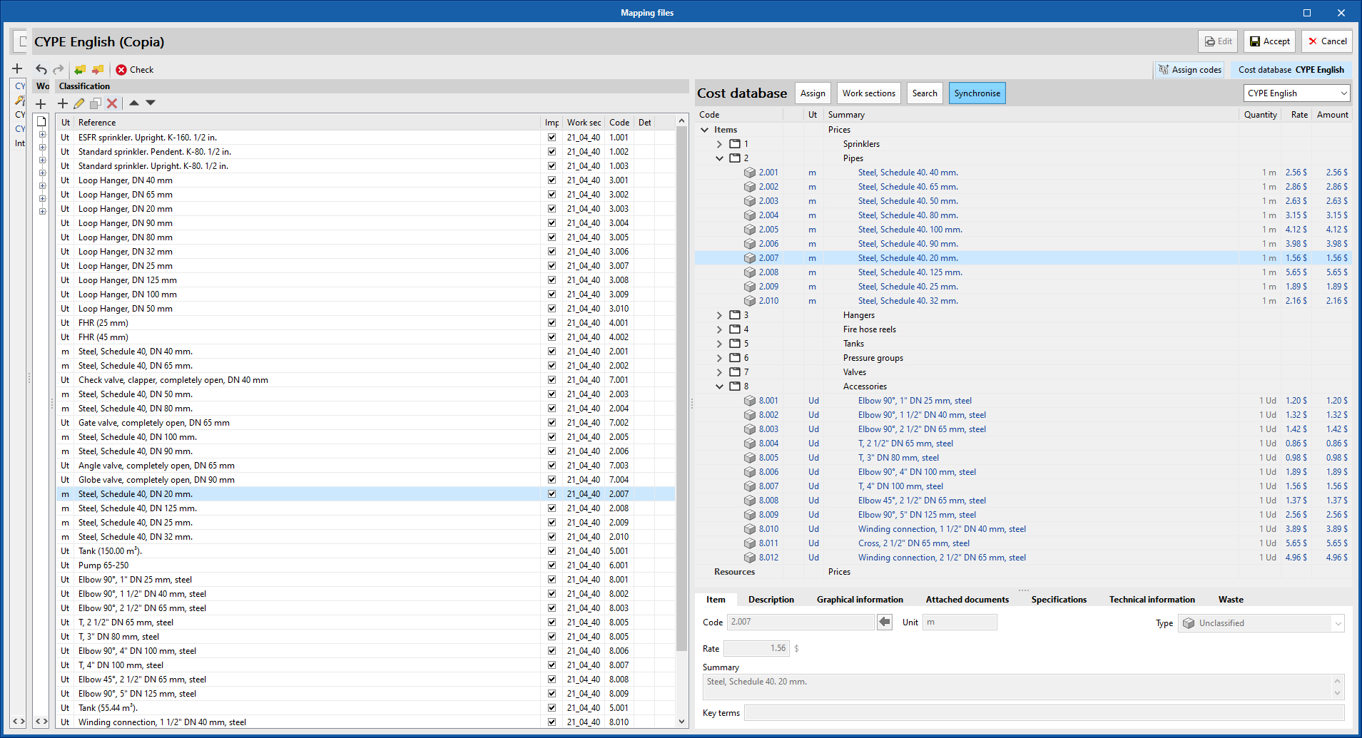
Edit interface for the "Sets of measurement rules" and "Mapping files"
In order to make it easier for the user to read and enter data, the appearance and size of the "set of measurement rules" (Open BIM Quantities) and "mapping files" ("Bill of quantities" tab) edit panels have been improved.
The application now allows users to considerably reduce the width of the windows containing the "set of measurement rules" (Open BIM Quantities) and "mapping files" ("Bill of quantities" tab) lists, as well as the chapter structure. In this way it is possible to free up more space for the rest of the panels where the specialist needs to see the most information ("rules of measurement", "classification" and "cost database").
The following table columns are adjusted to the contents of their cells without taking into account the heading:
- Import
- Operator
- Chapter
- Formula
- Group
- Detail line
Thanks to this modification, the empty space is reduced and a greater amount of text is displayed in the reference fields of the items and components of the BIM model.
Editing tools: cut, copy and paste
Options have been added to the toolbar to cut, copy and paste the concepts that appear in the bill of quantities table or in the prices of the job. As a result, it is now possible to easily move a concept from one chapter to another.
Assign chapters of the cost database to "Set of measurement rules" or "Mapping file"
As of the 2021.e version, it is possible to copy the chapter structure of the active cost database to the "set of measurement rules" (Open BIM Quantities) or to the "mapping file" (applications with the "bill of quantities" tab). In previous versions the chapter structure could already be imported from a FIEBDC-3 (.bc3) file, but now the process has been simplified since it is no longer necessary to export the cost database beforehand.
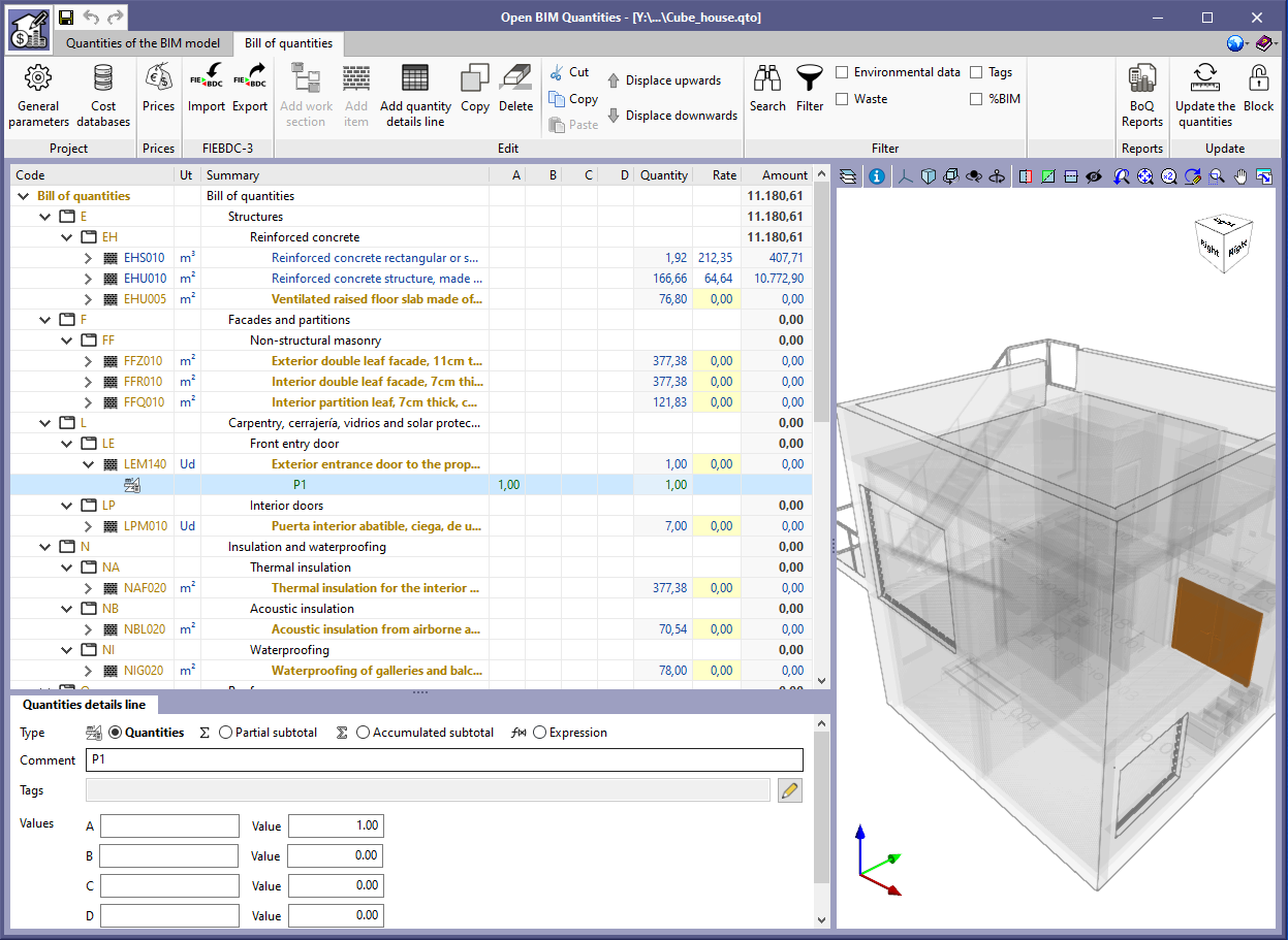
Open BIM Quantities
Example job update
The example job "Proyecto de edificio de viviendas", together with its associated cost database, has been updated to take into account both the specifications and the construction and demolition waste.
Applications with the Bill of Quantities tab
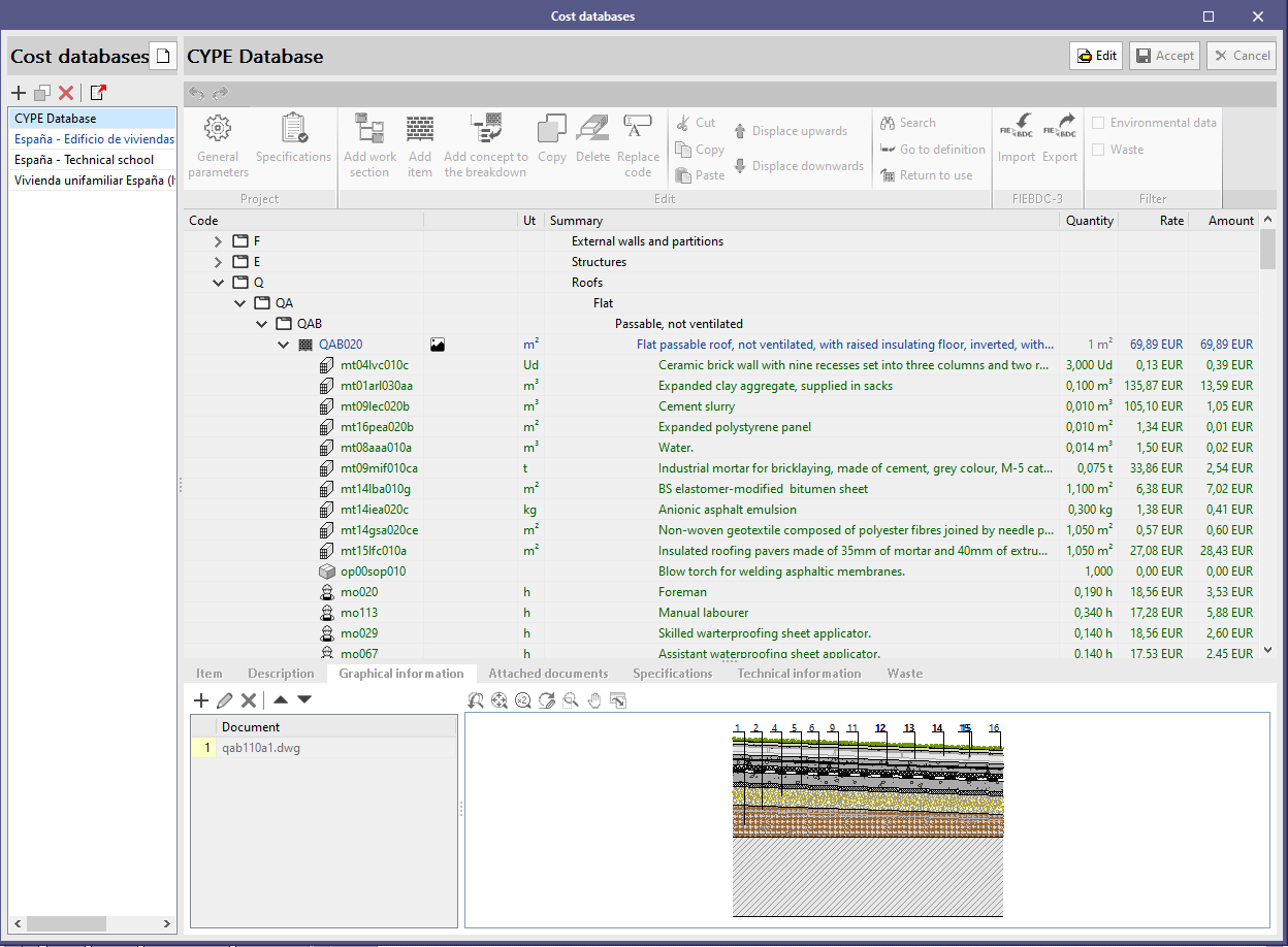
Information icons in the schedule of rates
A new column has been included in the concepts table that appears in the cost database and the prices of a project. In this column an icon will be displayed when the concept has data available on one of the following sections:
- Graphical information
- Attached documents
- Specifications
- Technical information
- Waste
This way it is easier to identify information and avoids problems of missing information in later stages of the bill of quantities.
Technical information
As of the 2021.e version, it will be possible to enter certain technical parameters associated with the items and resources defined in a cost database or the prices of a project. This data will be used to determine the environmental impact indicators and the construction and demolition waste of the job.
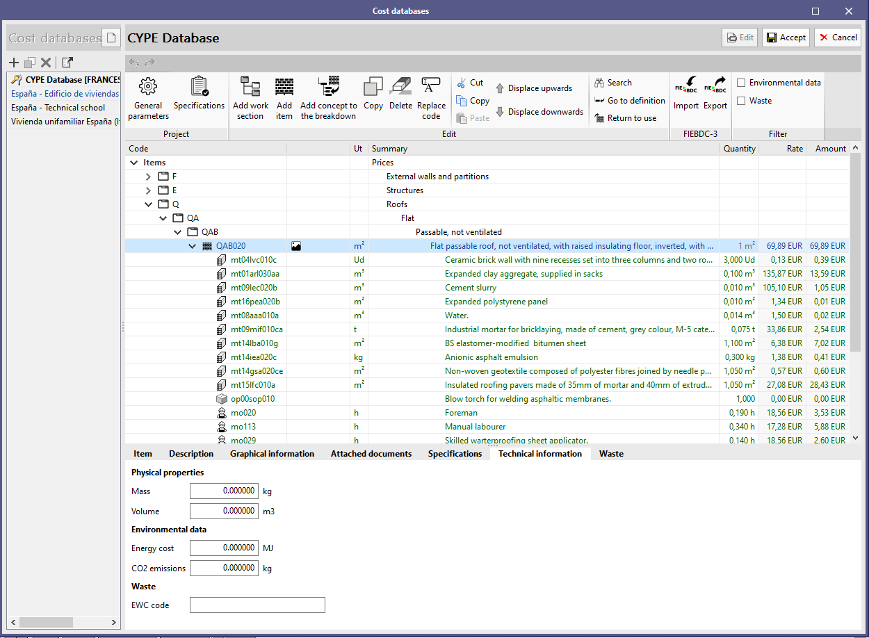
The following parameters are currently available:
- Physical properties
- Mass (kg)
- Volume (m3)
- Environmental data
- Energy cost (MJ)
- CO2 emissions (kg)
- Waste
- EWC code
- EWC code
The technical information of a concept can be imported or exported using a file in FIEBDC-3 (.bc3) format. Based on the specification of the standard, this data will be included in the ~X record.
Environmental impact indicators
Thanks to the implementation of environmental data in the definition of the job concepts, it is now possible to determine the value of the project’s environmental impact indicators.
The unit value of the energy cost (MJ) or the CO2 emissions (kg) of a simple element is introduced using the technical information parameters of the concept. However, for composite elements, these values are obtained by adding the components of the price breakdown ("performance" * "unit value of the component indicator").
To obtain the values of the project, the unit values of the environmental impact indicators are multiplied by the quantity assigned to each item.
In order to allow the calculated values to be viewed, the "Environmental data" option has been added to the "Filter" group in the application's toolbar. When activating it in a cost database or when defining the prices of the job, the unit values corresponding to the environmental impact indicators will be shown. If it is activated in the bill of quantities, the values calculated for the job will be shown, both for the items and the chapters. Additionally, in the "BreakDown" tab associated with each item, two new columns will appear with data on the energetic cost and the CO2 emissions corresponding to the breakdown of the concept.
Finally, to document this information an "Environmental impact indicators" report has been added, which can be generated from the "BoQ reports" option in the toolbar.
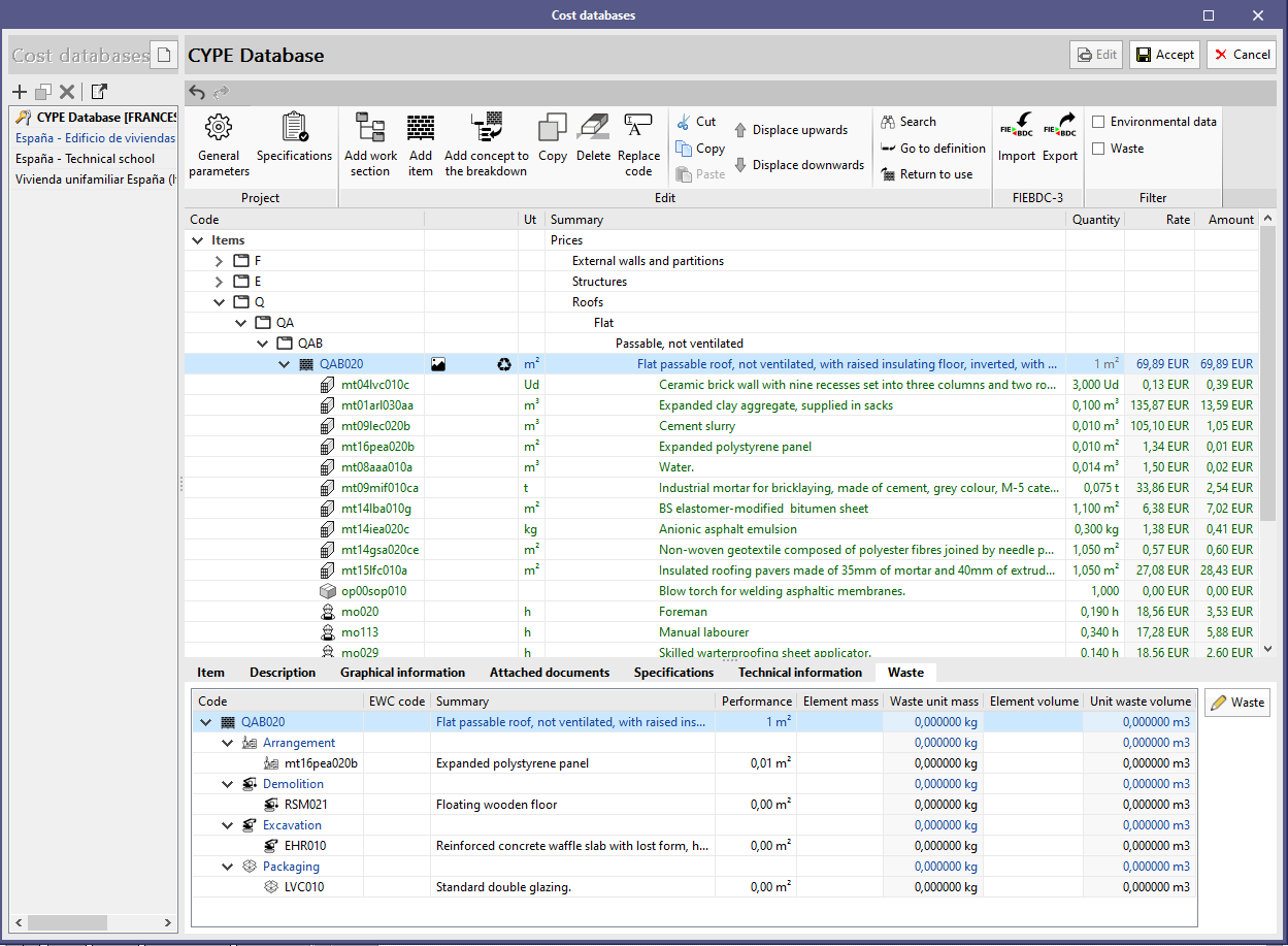
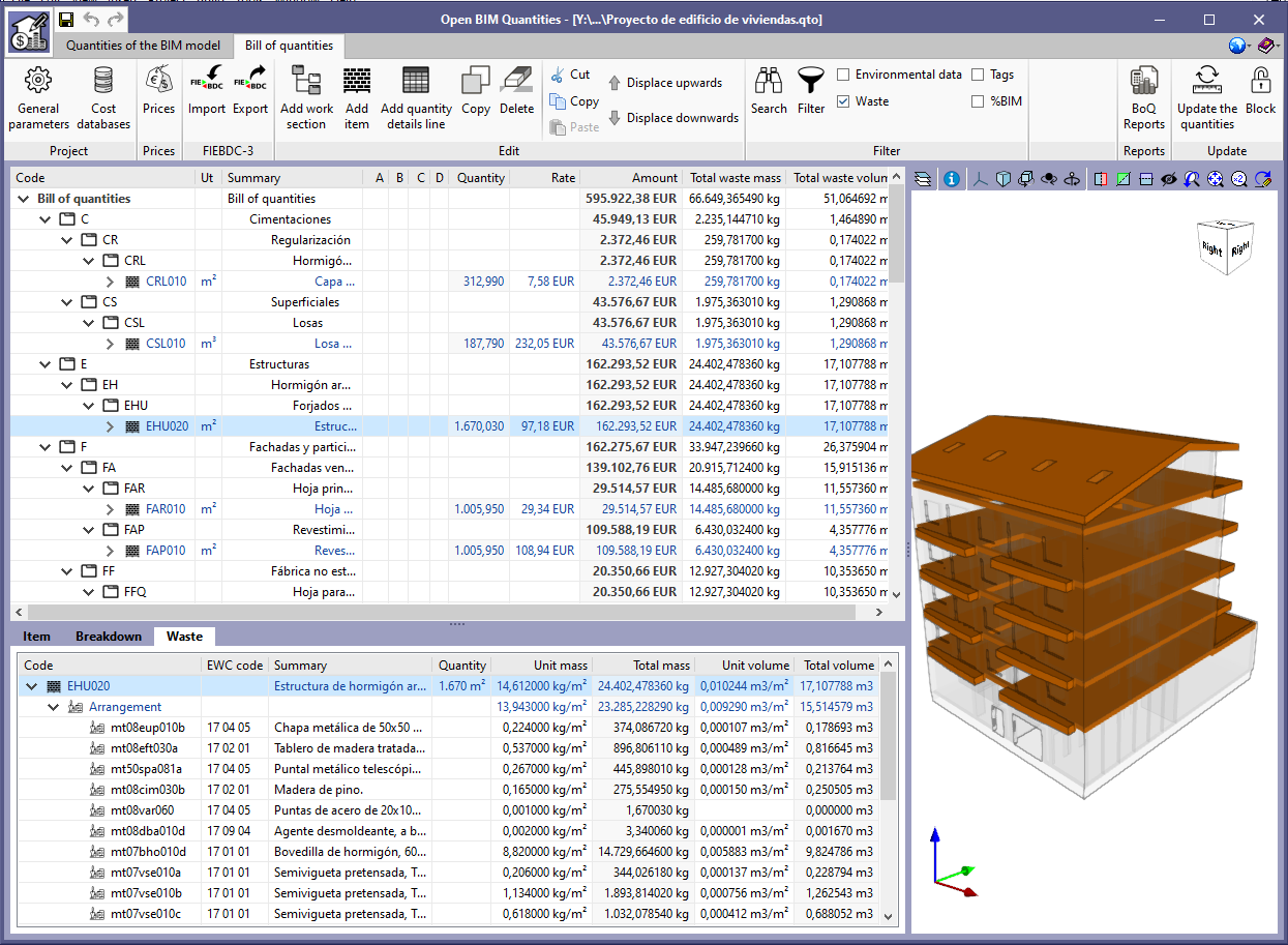
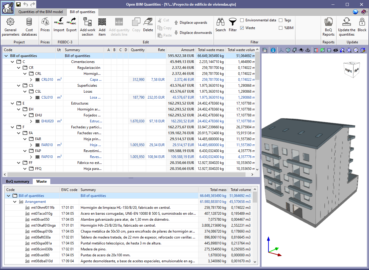
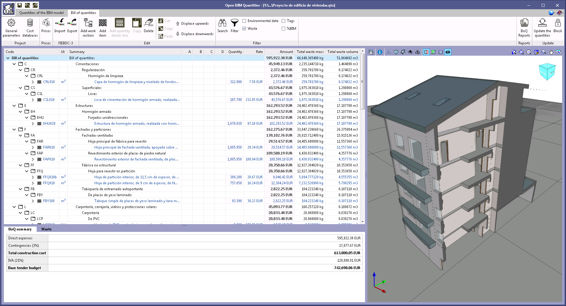
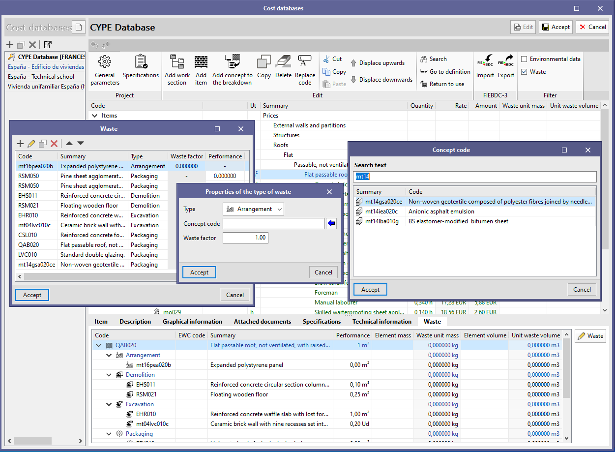
Construction and demolition waste
As of the 2021.e version, applications that include the "Bill of quantities" tab can obtain the waste decomposition of the project.
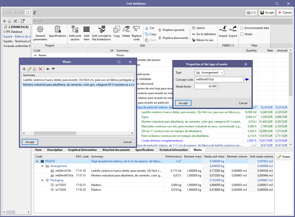
The waste decomposition of an item is defined in the "Waste" tab associated with the concept. When adding a waste component to the decomposition, the concept code and type must be entered. Four types of waste have been defined:
- Arrangement
- Demolition
- Excavation
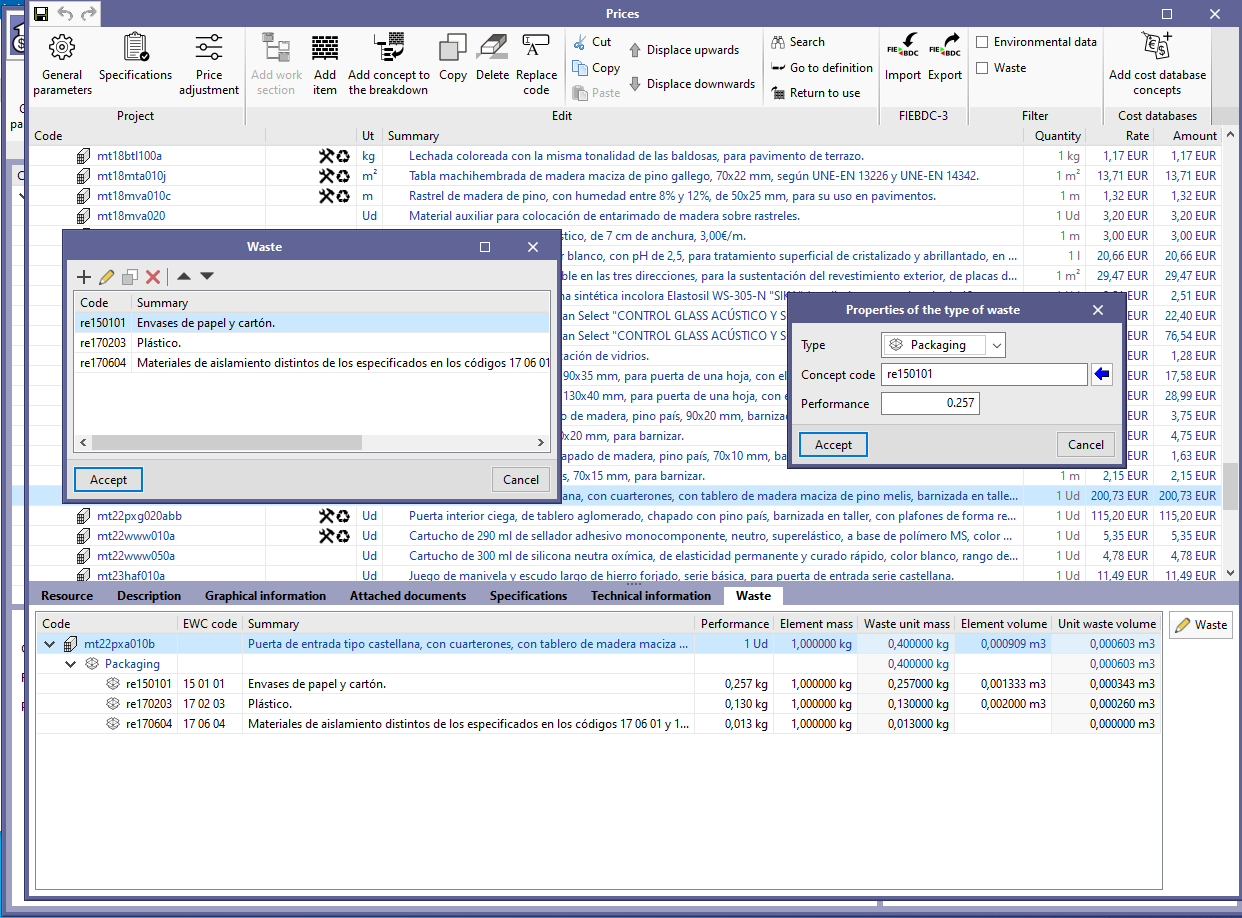
- Packaging
Arrangement waste refers to concepts that are already included in the price breakdown of the item. If this type is selected, a "waste factor" value must be entered. The "waste factor" represents the quantity of material, relative to the performance of the item’s compound concept, that is disposed of during the construction process.
On the other hand, the demolition, excavation and packaging waste correspond to concepts defined with the "Waste generated" type. This new type has been added in this version to represent simple concepts that only form part of the waste decomposition of items.
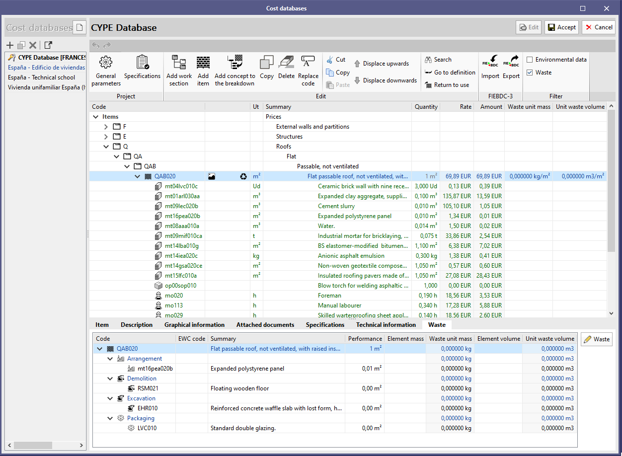
Once the waste decomposition of an item has been completed, its unit waste volume and waste unit mass values are automatically calculated. We can also see the subtotals referring to each type of waste.
Similarly to the environmental impact indicators, the "Waste" option has been added to the "Filter" group in the toolbar. On activating it in a cost database or in the price definition of a job, the waste unit mass and unit waste volume values will be displayed in the schedule of rates. If it is activated in the bill of quantities, it will display the values calculated for the job, both in the items and the chapters.
In the items and chapters of the bill of quantities a "Waste" tab has also been added, as well as in the prices. However, in this case the total waste mass and volume results will appear, that is, the unit values multiplied by the quantity of the item.
The waste decomposition of a concept can be imported or exported using a file in FIEBDC-3 (.bc3) format. Based on the specification of the standard, this data is included in the ~R record.
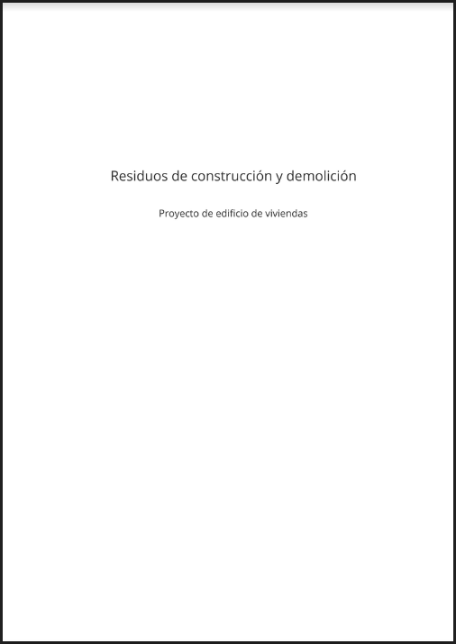
Finally, to document this information a "Construction and demolition waste" report has been added, which can be generated from the "BoQ reports" option in the toolbar.
Assign a chapter to a cost database in the mapping file
As of the 2021.e version, when clicking on the "Assign" option in the active cost database when editing the mapping file, the chapter code will be associated to the selected element in addition to the concept code. This implementation responds to the fact that usually the chapter structure of the mapping file corresponds to the chapter structure of a cost database.
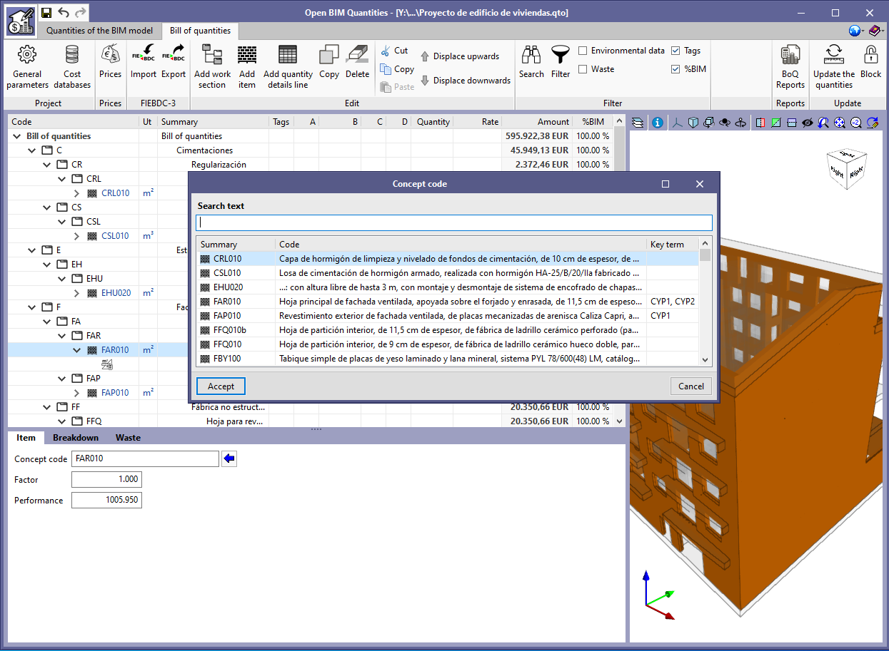
Code entry tool
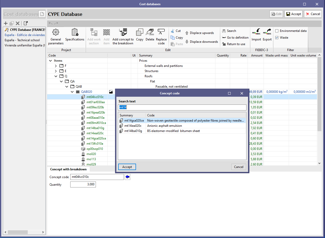
A tool (blue arrow) has been added to search for the code of a concept in the following points:
- "Prices" window of the job or the "Cost databases"
- When entering the code of a concept.
- When adding a concept to the breakdown of an item.
- When adding a component of the waste breakdown of a concept.
- "Bill of quantities" window
- When adding a new concept from the job prices to the bill of quantities.
Return to the 2021 version download area
Tel. USA (+1) 202 569 8902 // UK (+44) 20 3608 1448 // Spain (+34) 965 922 550 - Fax (+34) 965 124 950