
NEW PROGRAMS AND MODULES
Open BIM EFI
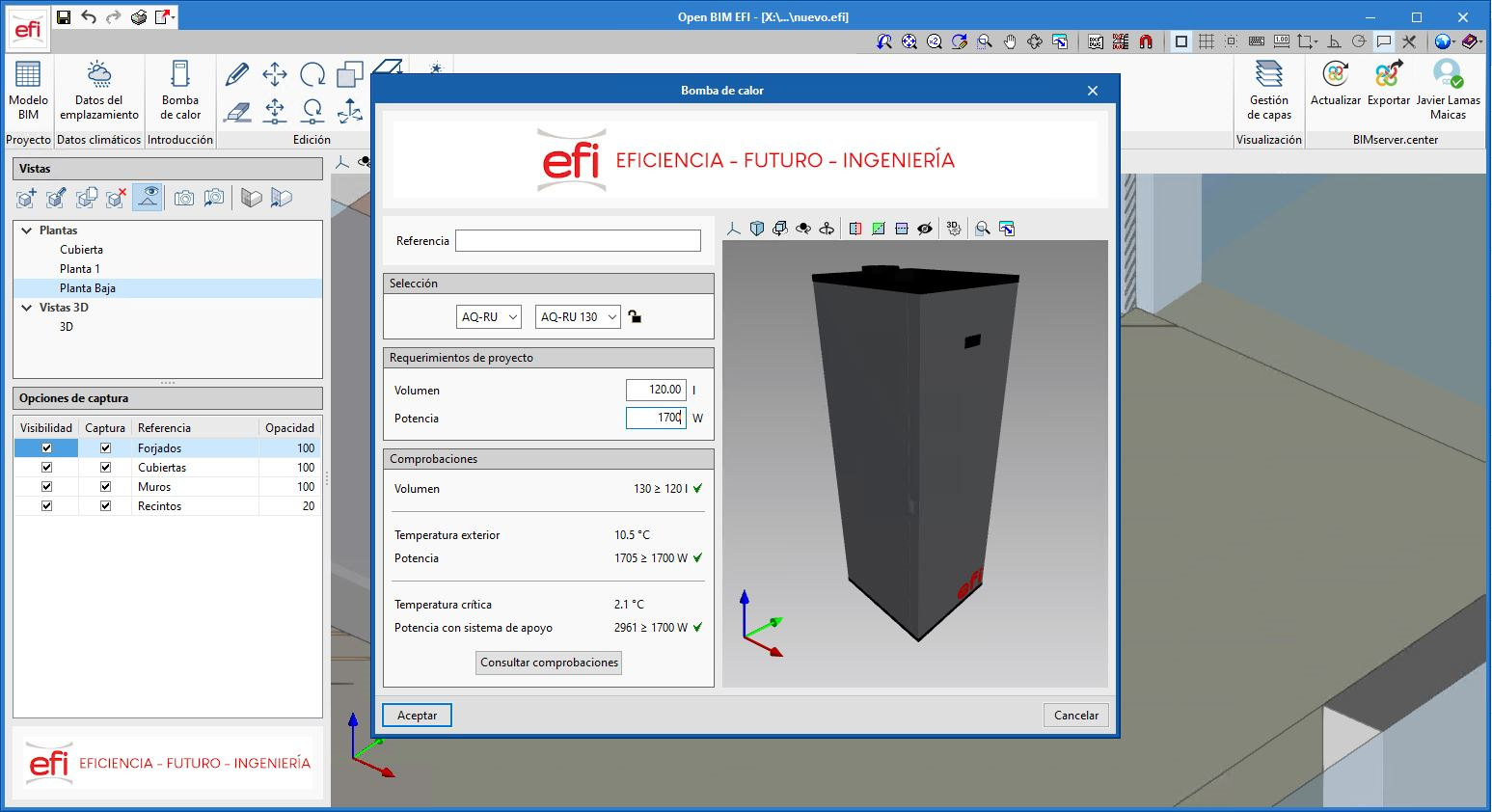
Open BIM EFI is a free tool developed by CYPE for modelling and selecting heat pumps for DHW installations from the manufacturer EFI.
The program is integrated into the Open BIM workflow via the BIMserver.center platform.
Open BIM EFI allows elements to be quickly and easily insierted into the 3D model, collecting the slab data from the architectural model of the project.
Once the equipment has been inserted into the model, the program carries out the relevant checks on the selected heat pump (volume, thermal capacity and critical capacity).
Open BIM EFI generates a calculations justification document and a materials list with a report of the selected equipment.
More information (Spanish).
Open BIM Sampling
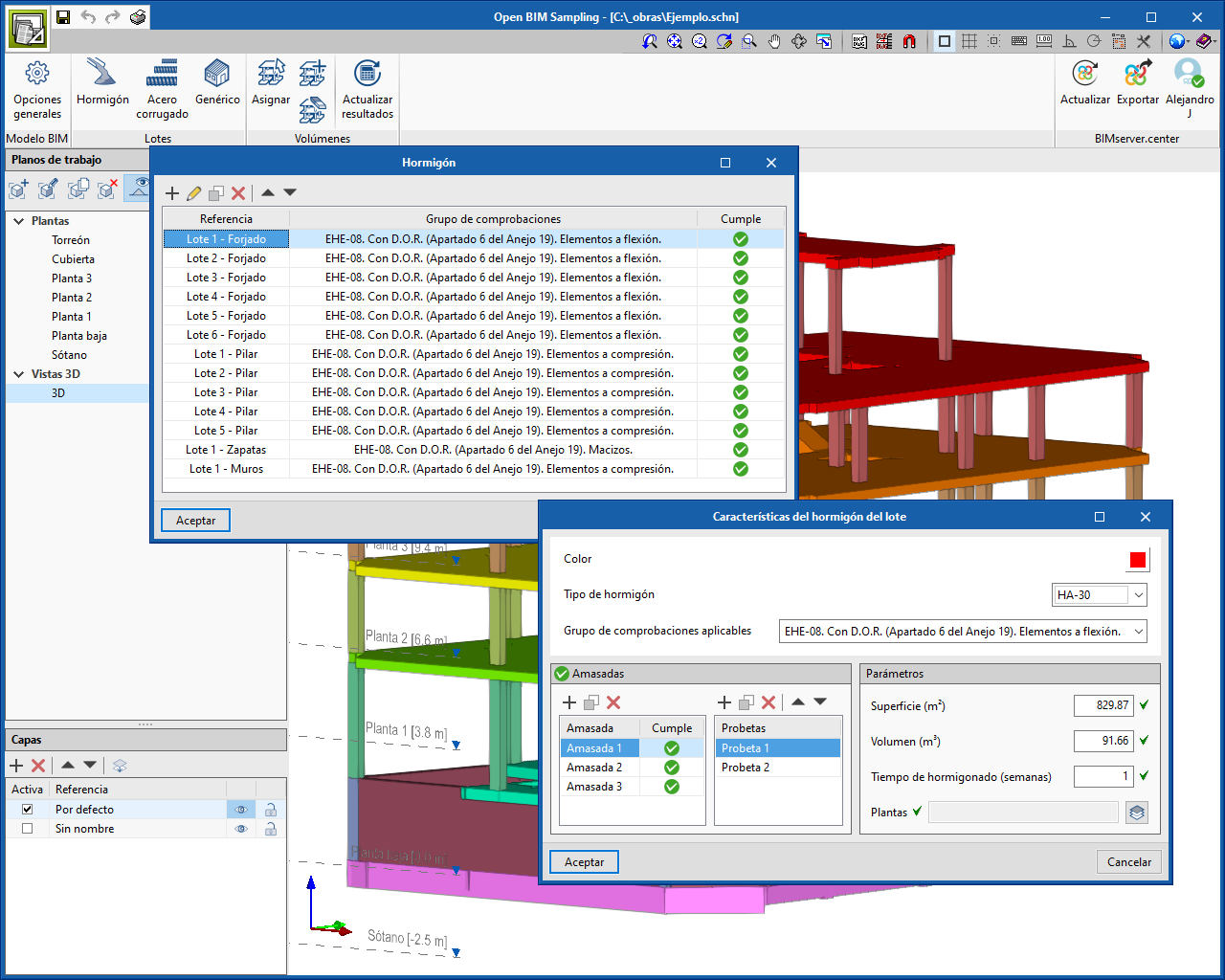
Open BIM Sampling is an application for the generation of batches and samples for the quality control of products used in the execution of works. It is integrated into the Open BIM workflow via the BIMserver.center platform.
The program allows users to generate the checks to be carried out on batches (area, volume, etc) and it also contains the codes defined in the Spanish building code HE-08 for both concrete and steel.
Open BIM Sampling obtains the documentation for the justification of the quality control planning and exports it in an Open format to BIMserver.center.
More information (Spanish).
Kroqi 2 BIMserver
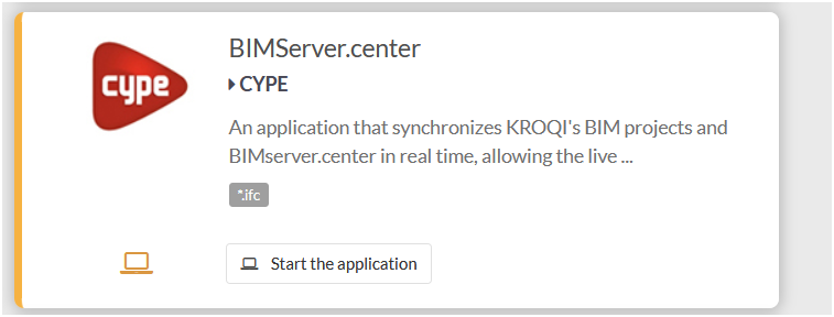
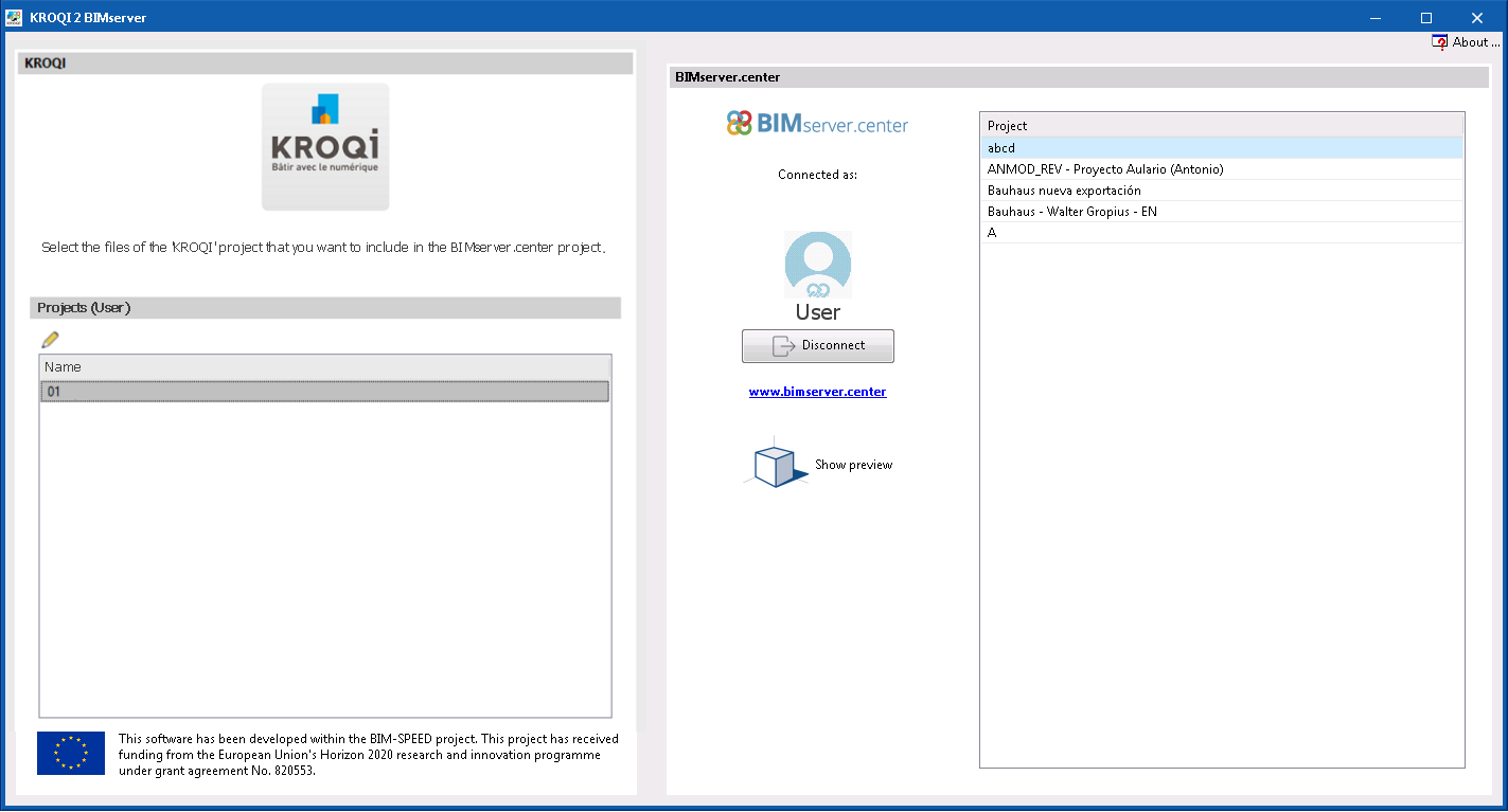
“KROQI 2 BIMserver” is a free program with which the KROQI platform can communicate with BIMserver.center, allowing for files to be exchanged between the two.
“KROQI 2 BIMserver” users can work on both repositories and make the most of their features in the same project, and so all the information is synchronised.
“KROQI 2 BIMserver” is integrated into the Open BIM workflow.
NEW FEATURES OF EXISTING PROGRAMS
Open BIM POLYTHERM
Update of POLYTHERM products
In the 2021.d version of Open BIM POLYTHERM, all products available in the program for the design of radiant floor installations have been updated with the latest price published by the manufacturer.
Open BIM ROTH
Update of ROTH products
In the 2021.d version of Open BIM ROTH, all products available in the program for the design of radiant floor installations have been updated with the latest price published by the manufacturer.
CYPE Architecture
New features in the "Edit" menu
Two new features have been introduced in the “Edit” menu of the “Architecture” tab toolbar:
- Copy properties
Allows properties (Reference, Level, Label, Colour, etc) to be copied between elements of the same type.
To copy the properties of an element follow the steps below. Remember that properties can only be copied between elements of the same type.
- Click on “Copy properties” in the “Edit” menu.
- Select the element whose properties you wish to copy.
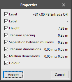
- A window will appear with a list of properties that can be copied and their values.
- Choose the properties to be copied and click on accept in the panel.
- Select the elements where the selected properties will be copied.
- The properties will be automatically transferred to the selected element.
- Measure area
Allows the measurements of an area to be obtained by selecting on screen the points of the polygon that define it. Both the area and the dimensions of the perimeter lines outlining the polygon are obtained.
The dimensions are saved in the program and can be viewed again at any time by clicking on the “Measure area” button again. To delete the saved areas from the memory click on “Delete measurements”.
Other improvements
- In walls
- New basement wall category. Allows for an improved connection with Open BIM Analytical Model.
- The walls capture ramps, stairs and lifts.
- Automatic regeneration of the 3D model of the walls after clicking on accept in the BIM model panel.
- Correction of an error when drawing the wall by polyline on a sloped surface.
- Correction in the export of the net and gross area so it can be correctly read in Open BIM Quantities.
- In curtain walls
- The “Opening” button also deletes the mullions and transoms from the curtain wall.
- The export of the curtain wall mullions has been corrected so that it can be correctly read in other programs.
- En louvres
- The louvre is drawn on screen at the same time as it is being inserted, in the same way as for the curtain wall.
- The louvre is drawn on screen at the same time as it is being inserted, in the same way as for the curtain wall.
- In columns
- The rotation angle of the column can be indicated upon being inserted. Columns introduced successively will appear in the same direction.
- When editing the size of the column it moves.
- The column does not rotate when using the “Rotate” button in the “Edit” menu.
- In floor slabs
- A new category of external floor slabs has been included, which allows for improved connection with Open BIM Analytical Model.
- Correction in the export of the net and gross areas so that they can be read correctly in Open BIM Quantities.
- In windows
- The windows include the adjustment of the frame.
- When a window is inserted, its position of alignment with the wall can be chosen.
- The same insertion point is maintained for all windows introduced simultaneously.
- In doors
- The button "Change opening direction" has been included in the menu to change the opening direction of the doors.
- The doors include the adjustment of the frame.
- When a door is introduced its position of alignment with the wall can be chosen.
- The drawing of the doors has been corrected when choosing any insertion point.
- The error produced when inserting a door into a sloped wall has been corrected.
- In openings
- New opening by points feature with the “Opening” button.
- When an opening is inserted its insertion point can be chosen.
- The error produced when deleting an opening dependent on a door has been corrected.
- In roof tiles, ridges and valleys
- Improved captured of perpendicular, tracking and intersection types.
- Improvements in drawing the label on the space.
- It is possible to change the size of the text drawn on the space.
- In furniture
- A button has been included which allows for the simultaneous rotation of various items of furniture.
- The error produced when introducing cupboards and worktops and clicking “shift” at the same time has been solved.
- In the BIM model
- The BIM model shows all the element data, including the label and the level.
Open BIM Layout
"Organisation". New section in the toolbar
The new "Organisation" section contains the tools needed to control the order in which the elements of the drawing overlap. In this section there are five features:
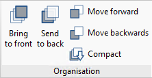
- Bring to front
Brings the selected element to the front among the overlapping elements. - Send to back
Sends the selected element to the back among the overlapping elements. - Move forward
Moves the selected element one level forward among the overlapping elements. - Move backwards
Moves the selected element one level back among the overlapping elements. - Compact
Reduces the distance in depth between the elements of the drawing to the minimum possible, while maintaining the relative order between them.
"Area". New feature in the "Dimension" section
In the dimension section of the toolbar users can find the new "Area" feature. With this feature surfaces can be measured in the 3D scene and their area obtained in text format.
Follow the steps below to generate areas:
- To measure an area draw a polygon containing the area by clicking on the elements of the 3D scene on the screen.
- Click one by one the vertices of the polygon that define the area to be measured.
- Once the area is closed, indicate where to enter the text with the measurement.
- Manually add a text if desired. This text will accompany the measurement of the area.
- Accepting the panel and the measurement with the text, the polygon containing the area will appear drawn on the sheet.
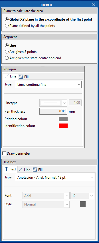
During the introduction, from the Edit button users can choose the line and fill styles, both for the text box and for the polygon outlining the area.
Other improvements
- Dimension: define user value
The user can manually change the dimension value by using the Edit button, activating the "check" in "user-defined value" in the edit panel. - Dimension: choose distance
The program offers the possibility of measuring the "real distance" or the "apparent distance". The real distance allows sloped planes to be measured from a floor or elevation view. - Print with alerts
It is possible to print even if there are error alerts due to elements located outside the sheet area.
CYPECAD
Customised reports. New predefined reports
The following predefined reports have been added, so users may add them as chapters in the customised reports:
- Joist takeoff
- Form takeoff
- Joist floor slab reinforcement takeoff
- Hollow core plate takeoff
- Hollow core plate reinforcement takeoff
- Composite slab reinforcement takeoff
Lock punching shear perimeters
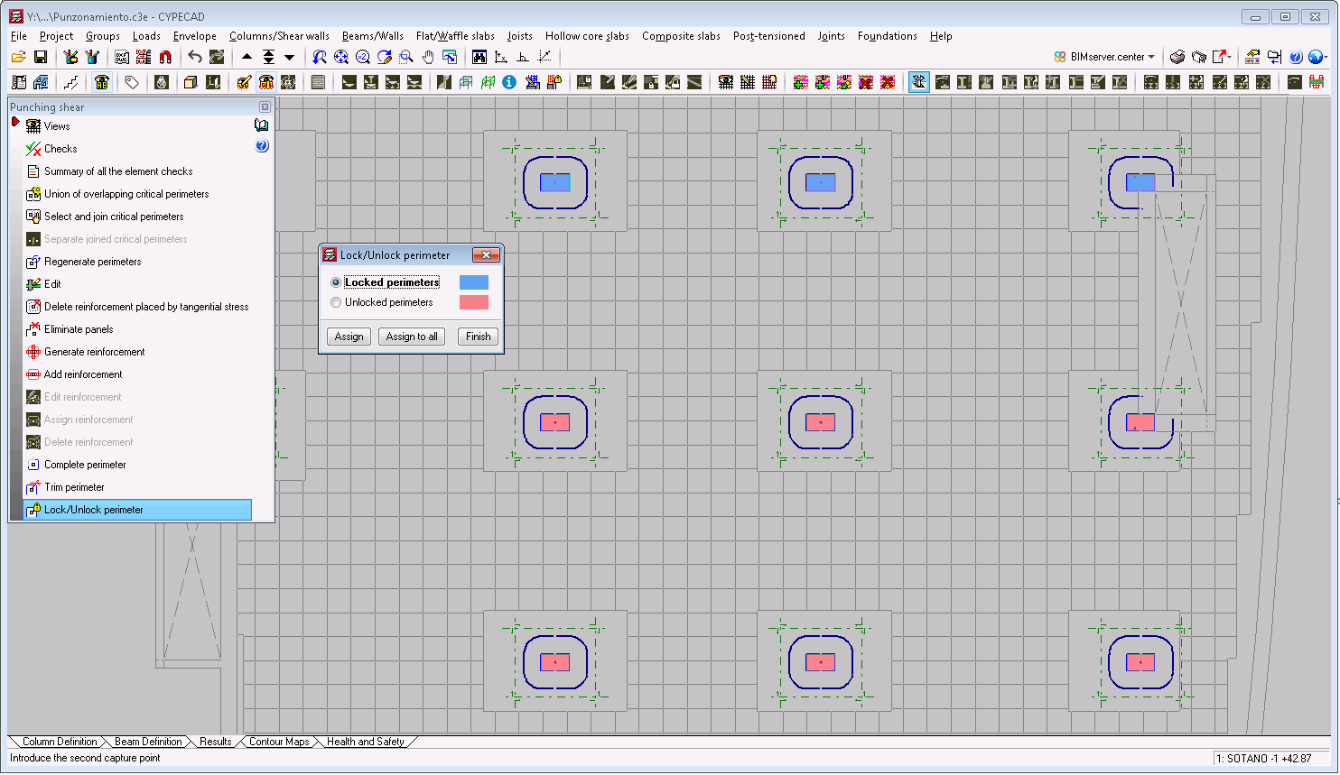
The 2021.d version includes the new tool "Lock/Unlock perimeter" in the "Punching shear" option ("Results" tab > "Slabs/Waffle slabs" menu > "Punching shear" option). Using this tool, users can lock as many perimeters of the supports as they wish. This way, each time the project is analysed or when punching shear perimeters are regenerated, only those that have not been locked will be generated.
Other improvements and corrections
The 2021.d version of CYPECAD also includes other minor program improvements and corrections of issues that could occur in unique cases:
- The "Surface loads on panels" option has been improved and users can select panels that are completely surrounded by others.
- Warnings when assigning walls that appeared repetitively have been eliminated.
- The values of the "Groups" > "Options – 3D view" option are saved.
- The values that are shown in the "Damping" help box of the "Norma de Construcción Sismorresistente NCSE-02" have been corrected.
- After using the "Loads" > "Change loadcase assignment" option, the floors on which changes have been carried out are automatically saved.
- An error in the "Reinforcement quantities, per diameter" report has been solved. When the "Detail base reinforcement on drawings" option was active, the base reinforcement total was twice the actual value in the summary of the quantities.
- An error has been solved, which caused an increase in the length of a frame in cases as shown in the image.
- An error has been solved that occurred when users tried to obtain the frames drawing having deleted all the sections when the frame had been edited.
- An error has been solved that occurred when users consulted the deformed shape having deleted loadcases that had been consulted previously.
- An error has been solved that occurred when users cancelled the selection of the form in "Panel manager > Waffle slabs > Import from library".
- An error has been solved that occurred when stairs were entered in groups that had been added below foundation level, which caused for them to be added to the group above.
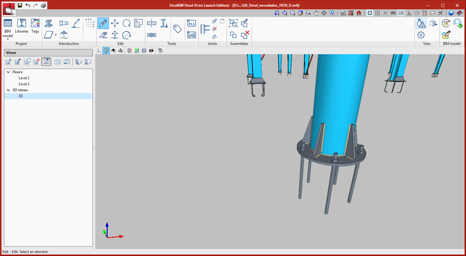
StruBIM Steel
New types of connections
The following types of connections have been implemented:
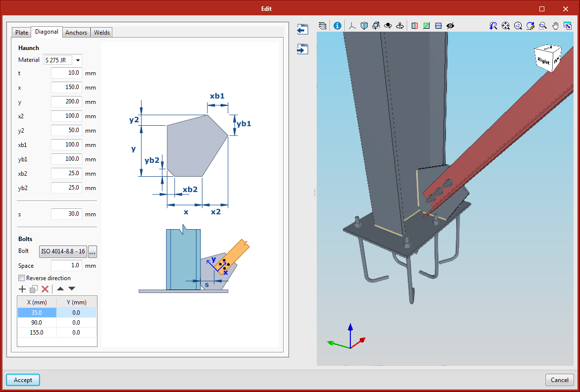
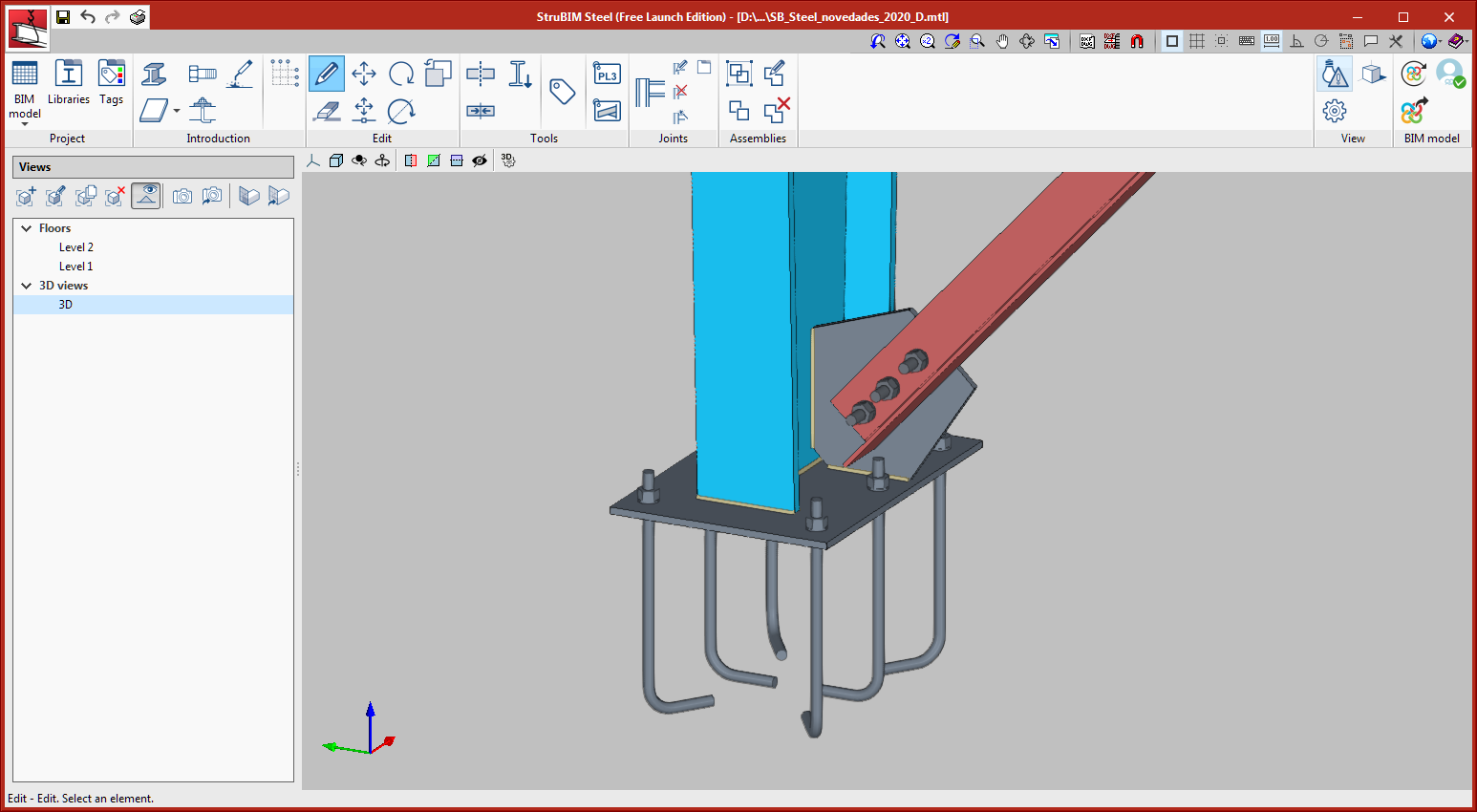
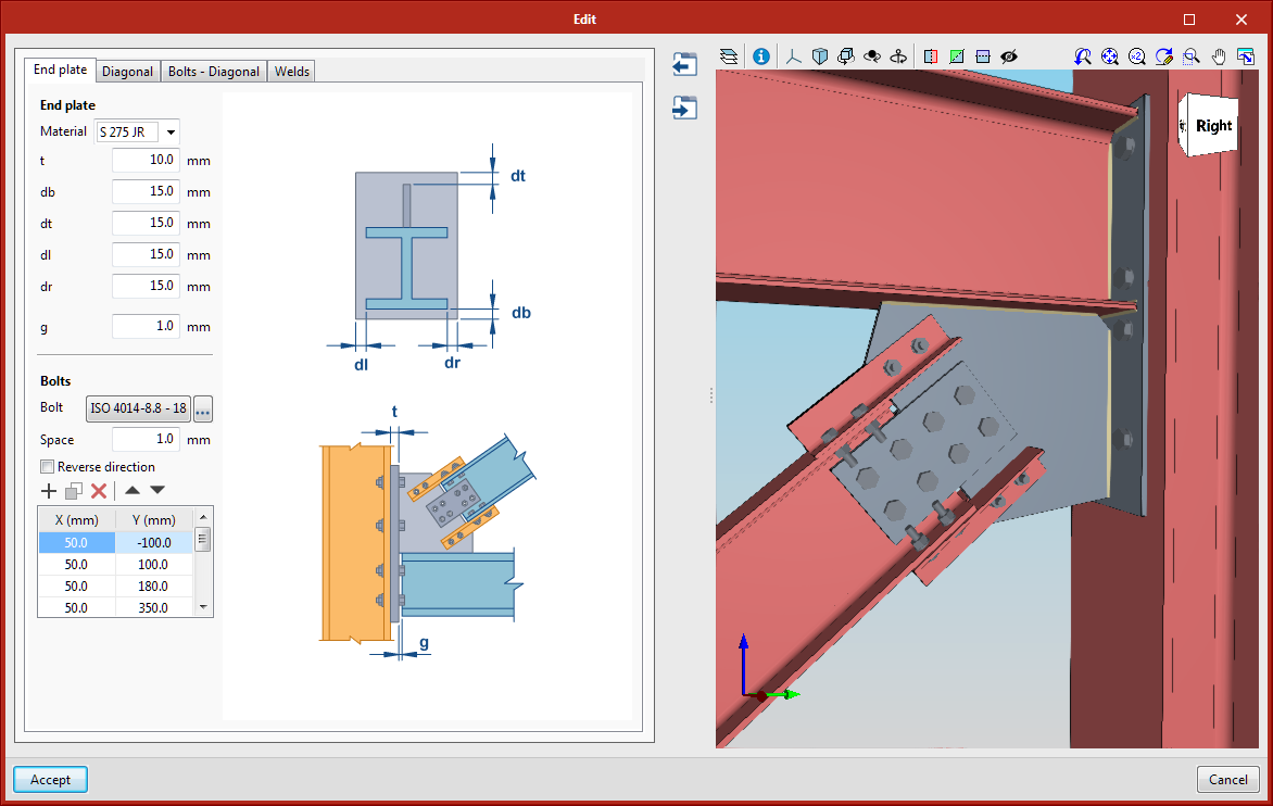
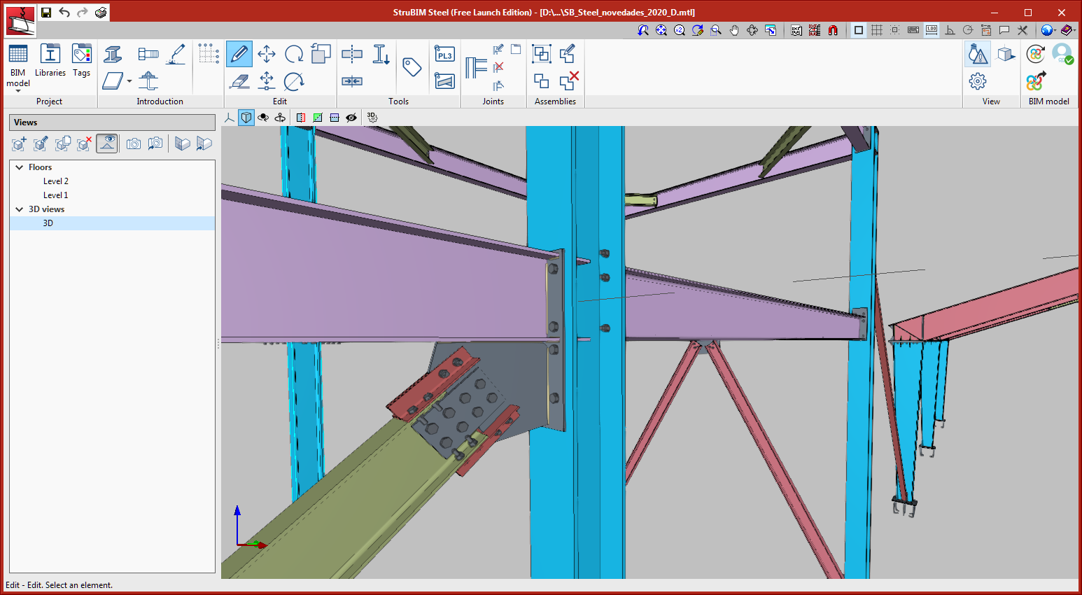
Baseplate with bolted diagonal
This connection allows for the main section to be a rolled or built-up rolled I type, and for a circular hollow section or rectangular tube. The diagonal that is bolted to the haunch can be an angle, U or plate type.
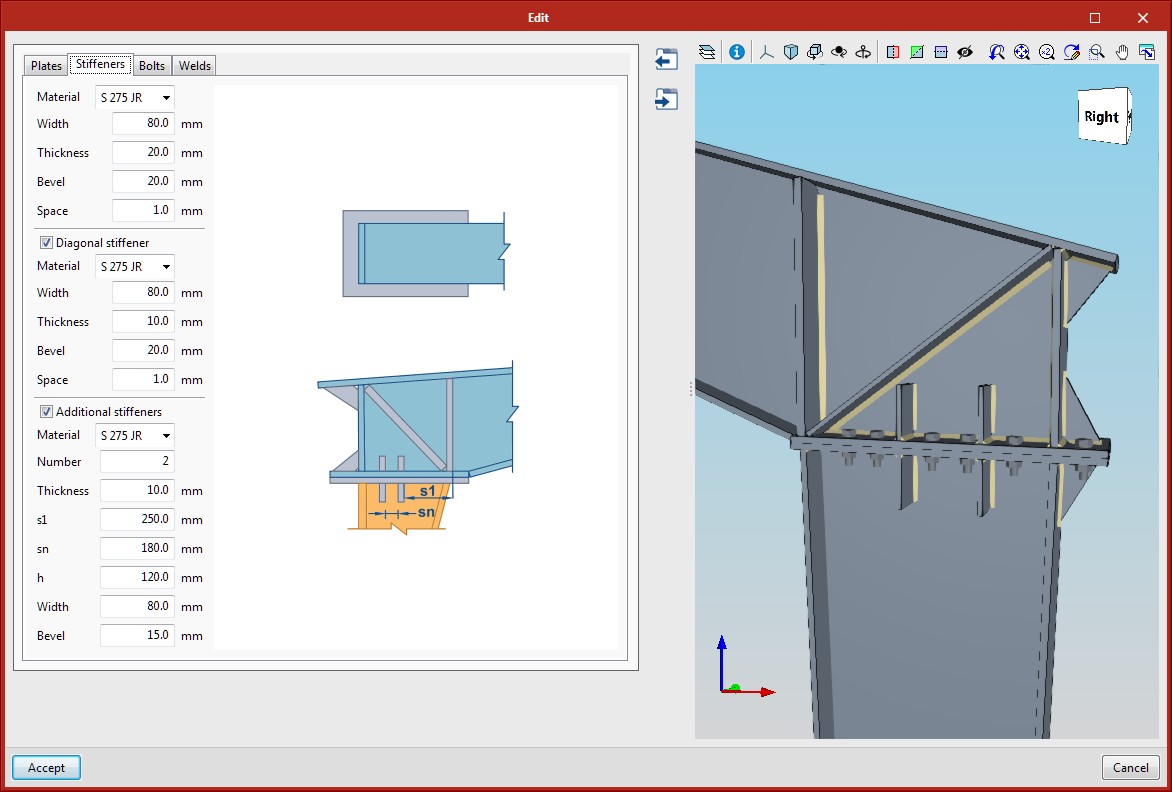
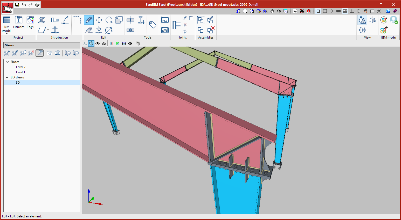
Beam-to-column joint with built-up variable sections
This connection allows for the column to be a rolled double I or built-up double I with constant depth, or built-up double I with variable depth, the beam must be a built-up double I reinforced with variable depth. The beam is connected by an end plate bolted to the top of the column.
Column-to-beam joint, at the column web with plates bolted to the web and flanges
This connection is applicable to rolled double I-type sections. The beam is connected to the column by an end plate bolted to the column flange or web. The diagonal is joined to the haunch with angles bolted to the flanges and cover plates to the web.
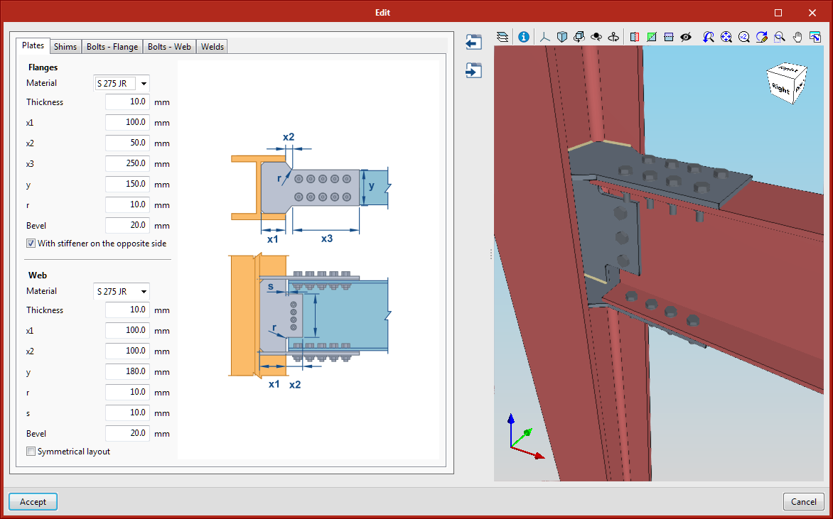
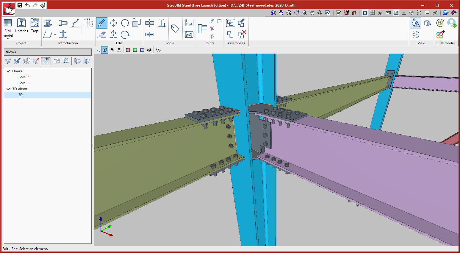
Connection between column, beam and diagonal
This connection is applicable to rolled double-I type sections. The beam is connected to the column by an end plate bolted to the column flange or web. The diagonal is joined to the haunch by angles bolted to the flanges and a cover plate bolted to the web.
Circular tube splice connections
This connection allows two aligned tubes, of the same or different diameters, to be bolted together using a circular end plate.
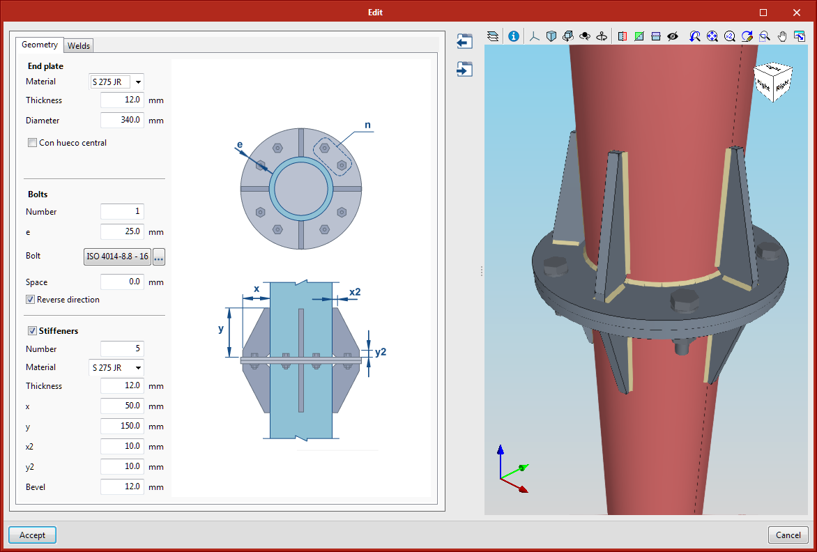
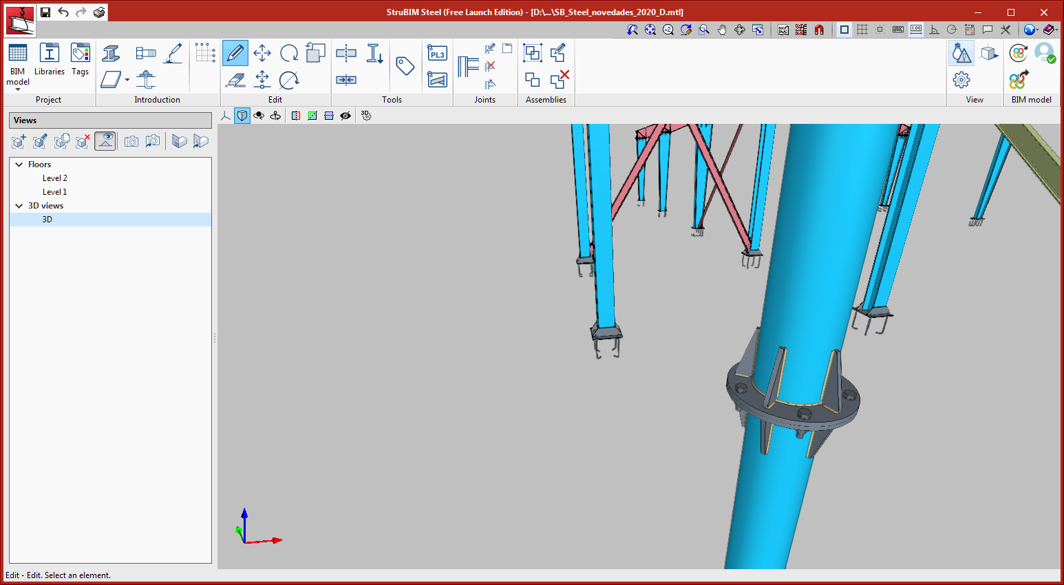
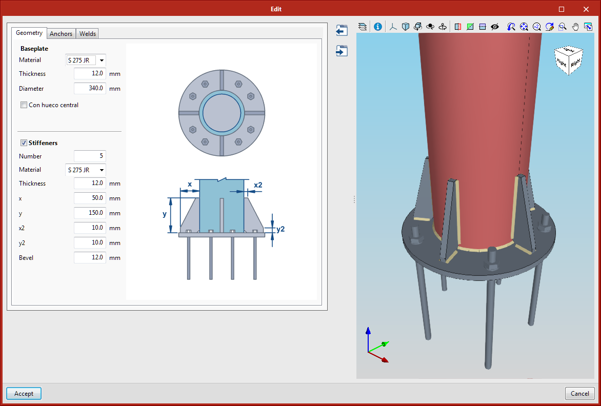
Baseplate for circular tubes
This baseplate is applicable to circular tubes, the anchor plate is circular, with a radial distribution of stiffeners and bolts.
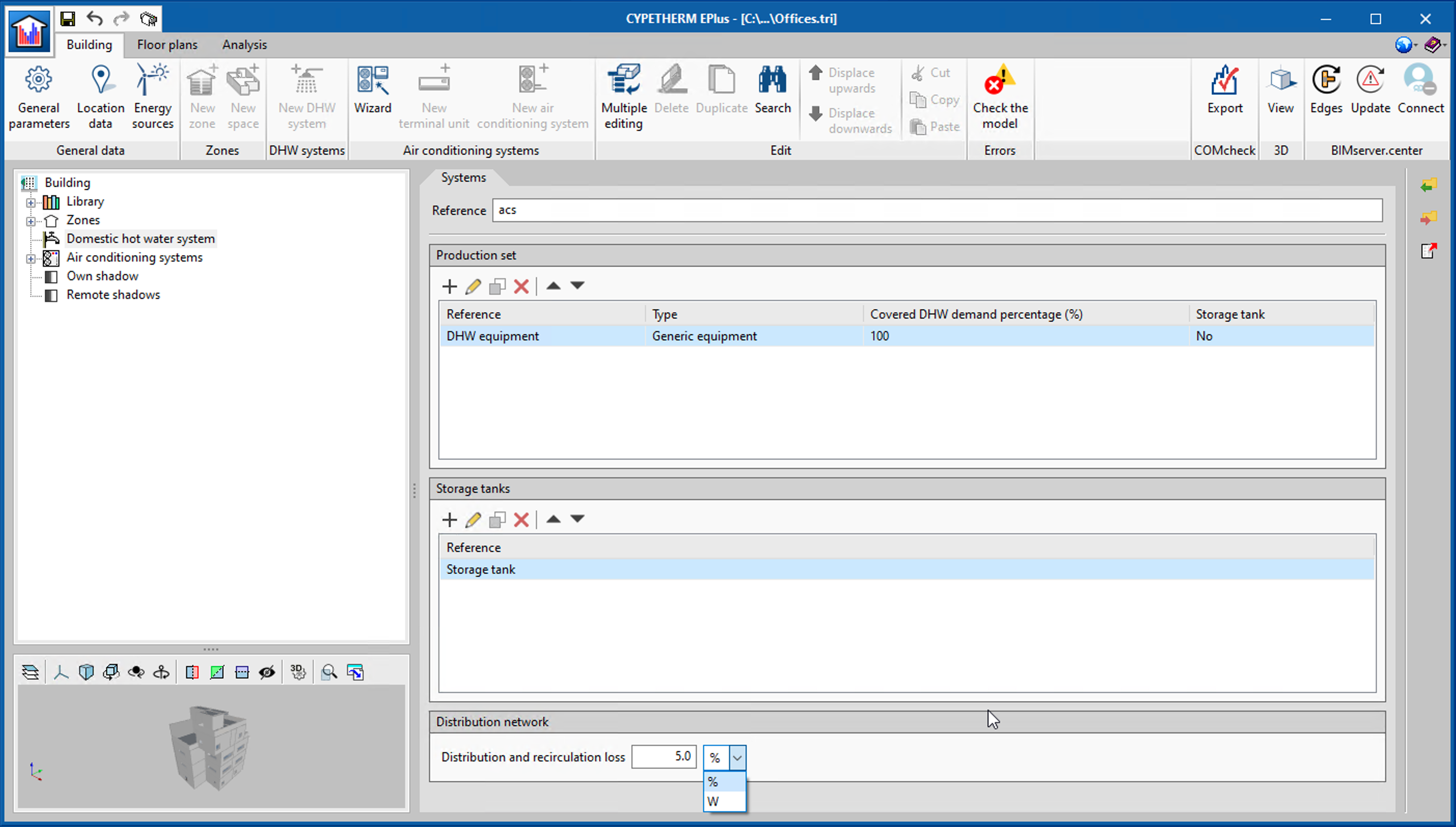
CYPETHERM EPlus
Distribution and recirculation loss in DHW systems
The new "Distribution network" section has been included in the definition of DHW systems, in which the user can define the heat loss due to distribution and recirculation in the DHW installation in watts (W) or as a percentage (%) of the DHW demand.
Return to the 2021 version download area
Tel. USA (+1) 202 569 8902 // UK (+44) 20 3608 1448 // Spain (+34) 965 922 550 - Fax (+34) 965 124 950