
- 64-bit version
- New modules and programs
- Improvements in code application
- Open BIM Carpentry
- Open BIM Sanitary Equipment – Open BIM Water Equipment
- Open BIM Electrical Mechanisms
- Open BIM Accessibility
- CYPECAD
- CYPE 3D
- StruBIM Anchors ACI 318
- CYPECAD MEP
- CYPELEC Core
- CYPELEC Networks
- CYPEPLUMBING Water Systems and CYPEPLUMBING Solar Systems
- CYPEPLUMBING Sanitary Systems, CYPEPLUMBING Water Systems and CYPEPLUMBING Solar Systems
- CYPEFIRE Sprinklers
- Open BIM Toshiba
- CYPETHERM Schematics and CYPETHERM Radiant floor
- CYPETHERM Improvements Plus
- CYPETHERM programs with the EnergyPlusTM analysis engine (CYPETHERM EPlus and CYPETHERM RECS Plus)
- Reduction in the analysis duration
- Definition of mixed equipment for heating and DHW using an assistant
- Estimate of the average seasonal performance of boilers for DHW production
- Ventilation via air conditioning systems
- Unknown adjacent spaces
- Report of linear thermal bridges
- Import Daikin Open BIM equipment
- Arquimedes
- Open BIM Cost Estimator
- Return to the 2019 version download area
64-bit version

As of the 2019.f version, CYPE programs (those downloaded from our website and those downloaded from the BIMserver.center platform) are compiled for 64-bit systems. The 64-bit compilation of CYPE software implies the use of the superior features of 64-bit processors and operating systems compared to those of 32 bits.
Please bear in mind that you must have a 64-bit operating system to be able to work with any 64-bit software.
In any case and as a temporary measure, the 2019.f version is available in 64 and 32 bits on the download area of our webpage. The programs that can be downloaded from the BIMserver.center platform are only available in 64 bits. If you have a 64-bit operating system, you can work with either the 64-bit and 32-bit version of our software, although we strongly recommend that you install the 64-bit CYPE software version.
You can see which operating system is installed on your computer by clicking on "Control panel > System".
Since 64-bit microprocessors began to be massively introduced into personal computers from 2003 and from the Windows XP version, Microsoft already offers the two versions of its operating systems (32 and 64 bits). We understand that almost all our users will have computers with 64-bit processors (x64) and 64-bit operating systems.
It could occur that a user may wish to work with a computer with a 64-bit processor but with a 32-bit operating system. It would be very strange if the computer had a 32-bit processor (x86 - computers over 15 years old). If any of these is your case, we advise you to talk to your hardware or software provider to update your situation as soon as possible. However, you can download the 32-bit version and work with CYPE programs that can be downloaded from our website until your situation is up-to-date.
New modules and programs
Architectural elements
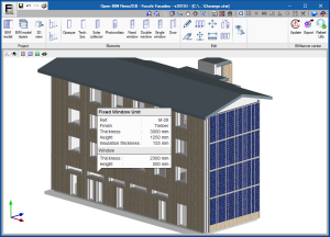
Open BIM RenoZEB – Focchi Facades
“Open BIM RenoZEB - Focchi Facades” generates the details of Focchi façades that have been designed especially for building rehabilitation.
The program is included in the Open BIM workflow and provides a report with the amounts and sizes of the panels that are required in the project, which will allow the company, Focchi, to manufacture the panels. These panels will also be drawn in 3D and will be introduced in the BIM model.
“Open BIM RenoZEB - Focchi Facades” has been developed as part of the RenoZEB research project (Accelerating energy renovation solutions for Zero Energy Buildings and Neighbourhoods) and is part of the strategic Horizon 2020 program of the European Union.
More information on this new application will be available shortly.
MEP
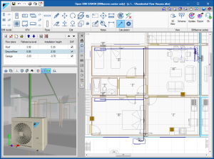
Open BIM DAIKIN
“Open BIM DAIKIN” is a free program that has been conceived to design air conditioning installations with Daikin variable refrigerant volume (VRV) systems.
It is included in the Open BIM workflow and can be downloaded from the BIMserver.center platform.
This first version of Open BIM DAIKIN can be installed in Spanish, Catalan or English.
More information on this new application will be available shortly.
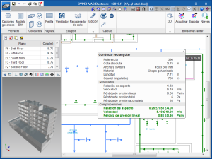
CYPEHVAC Ductwork
“CYPEHVAC Ductwork” is a tool to carry out the analysis and design of duct network projects based on an architectural model located on the BIMserver.center platform.
“CYPEHVAC Ductwork” is integrated in the Open BIM workflow using the IFC standard.
In order to use the program, the user license must contain the “Air conditioning ducts” permit, which is the same permit that is used to design duct networks in “CYPETHERM HVAC” and “CYPECAD MEP”.
“CYPEHVAC Ductwork” can be downloaded from the BIMserver.center platform.
More information on this new application will be available shortly.
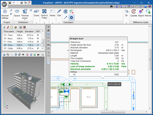
EasyDuct
“EasyDuct” is a free application to design duct networks using Soler&Palau (S&P) ventilation equipment based on an architectural model located on the BIMserver.center platform.
“EasyDuct” is integrated in the Open BIM workflow using the IFC standard and can be downloaded from the BIMserver.center platform.
More information on this new application will be available shortly.
CYPETHERM
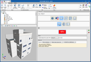
CYPETHERM FUJITSU
CYPETHERM FUJITSU is a program to model and perform the energy simulation of buildings with FUJITSU GENERAL AMERICA, INC. air conditioning systems using EnergyPlus™.
The program has been developed by CYPE for FUJITSU GENERAL AMERICA, INC., with the aim to facilitate the prescription of its products by incorporating the AirstageTM range of the VRF equipment from their commercial catalogue. This way, users can calculate the energy consumption of a building with AirstageTM air conditioning systems from FUJITSU GENERAL AMERICA, INC.
Although the user license is free andthe program can be used from the moment it is requested, FUJITSU GENERAL AMERICA, INC. reserves the right to deny authorization at any time to continue using the program.
The program is included in the Open BIM workflow and can be downloaded from the BIMserver.center platform.
More information on this new application will be available shortly.
Improvements in code application
Loads on structures. Wind loads
Wind load justification report
The codes for which this report has been implemented can be consulted in the “Wind load justification report” section of the new features of CYPECAD.
Loads on structures. Seismic loads
NC 46:2017 (Cuba)
Norma Cubana NC 46:2017. CONSTRUCCIONES SISMORESISTENTES - REQUISITOS BÁSICOS PARA EL DISEÑO Y CONSTRUCCIÓN.
Implemented in CYPECAD and CYPE 3D.
Fire protection installations
CP 52:2004 (Singapore)
Singapore Standard. Code of practice for automatic fire sprinkler system.
Implemented in CYPEFIRE Sprinklers.
More information in the new features of CYPEFIRE Sprinklers.
Open BIM Carpentry
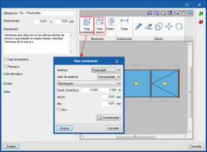
Opaque sections in windows
The panel to edit the types of windows has been improved: the elements a introduced more easily and users can select opaque sections.
Open BIM Sanitary Equipment – Open BIM Water Equipment
Increased program capacities
Open BIM Sanitary Equipment is now called Open BIM Water Equipment. This is due to the increased capacities of the program. Initially, the program was created to place bathroom equipment in the BIM model. Now, any type of equipment that requires a water connection in the building can be included: dishwashers, washing machines, kitchen sinks.
Larger elements catalogue
The number of elements included in the Open BIM Water Equipment catalogue has increase from 12 to 48 elements. This improves the adaptability possibilities to different types of spaces.
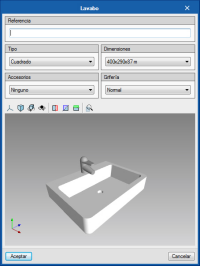
Element personalisation
The catalogue elements can be personalised. Users can configure:
- The shape of the sink (round, square or rectangular)
- The type of tap
- The type of support of the sink (free, with a cabinet, or with a pedestal)
New elements: Sinks, dishwasher and washing machine
The 2019.f version of Open BIM Water Equipment allows users to introduce new types of elements:
- Sinks
- Dishwasher
- Washing machine
Open BIM Water Equipment exports the new elements to the BIM model as it does with the rest of the elements that are available from previous versions. This way, programs that analyse and design wastewater evacuation installations (such as CYPEPLUMBING Sanitary Systems) or analyse and design drinking water supply installations (such as CYPEPLUMBING Water Systems) can read them and carry out their checks without having to introduce them again.
3D view of the equipment
A new view of the 3D elements is included. In previous versions, the view was carried out using a fixed image. Now, the view is carried out in 3D, which allows users to explore the different catalogue possibilities in a more dynamic way.
Open BIM Electrical Mechanisms
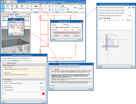
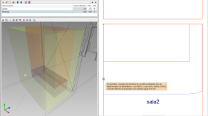
Protection volumes
The program offers users the possibility to define protection volumes corresponding to bathtubs or showers based on the dimensions of these elements.
The protection volumes depend on the location that contains the bathtub or shower, the separation from the walls and whether there are fixed walls.
The protection volumes are defined in international standard IEC 60364-7-701 and are the determinants for the positioning of the electrical mechanisms.
The program allows for the specifications of the aforementioned standard IEC 60634-7-701 to be loaded, as well as its transposition into Spanish, the standard UNE-HD 60364-7-701. This selection is carried out using the "Project" button in the toolbar.
With this selection the program loads the geometry corresponding to each of the volumes, as well as the permissiveness to contain electrical mechanisms inside them.
The program emits a warning when the electrical mechanism is inside an unauthorized volume or to provide information on the conditions if allowed.
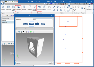
Switchgear envelopes
As of the 2019.f version, the following envelopes can be introduced in “Open BIM Electrical Mechanisms” so they can be represented on drawings and in the 3D view:
- Main breaker load centre
- Load centre
- Switchboard
- Secondary switchboard
Two icons have been implemented in the toolbar to introduce and position the envelopes.
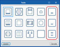
Mechanisms for USB and HDMI connections
Three new types of mechanisms have been included:
- Mechanism with USB connection
- Mechanism with HDMI connection
- Mechanism with USB and HDMI connection
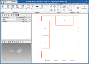
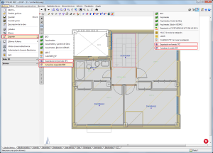
Reference elevation in the “Floor plans” table
In the Floor Plans section in the side menu of the program interface, a new column has been implemented: “Reference elevation”, which indicates the height of each floor of the architectural model of the project. This is very helpful when having to introduce the height of the electrical equipment.
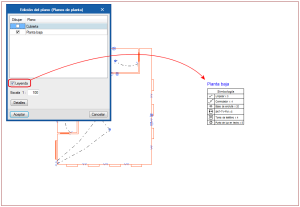
Key included in electrical drawings
The electrical drawing can include the key of the symbols that have been used. To do so, simply activate the corresponding “Key” option in the drawing generation process.
Export drawings and quantities to the BIM model
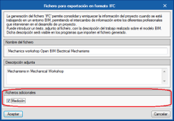
As of the 2019.f version, “Open BIM Electrical Mechanisms” exports the following documents to the BIM project to which the project is connected:
- Electrical drawing (DXF)
- Quantities report (PDF)
- Quantities (FIEBDC-3)
To be able to export the quantities (PDF and FIEBDC-3) the “Quantities” option must be activated in the dialogue box that appears when exporting to the BIM model.
Open BIM Accessibility
Collaboration agreement with the architecture and technical consulting firm Rovira-Beleta
CYPE and the architecture and technical consulting firm “Rovira-Beleta Accesibilidad” have signed a collaboration agreement whereby the latter will advise CYPE on the development and improvements of “Open BIM Accessibility”. By signing this agreement, CYPE will go one step further in the improvement of "Open BIM Accessibility" by implementing criteria that goes beyond that contemplated in the Spanish Technical Building Code.
New accessible elements
The 2019.f version of Open BIM Accessibility includes new accessible elements:
- Stairlift
- Wheelchair ramp
These elements provide accessibility in buildings with elevation changes.
New requirement: insufficient door width
“Open BIM Accessibility” detects if, along an accessible route, there are doors with insufficient width. In this case, the program displays the error on-screen and emits a warning from the “Requirements” section of the project located on the BIMserver.center platform and from the receptor program of the requirement or error, which in this case is the BIM modeller IFC Builder.
More information can be found on the Requirements in the Open BIM workflow webpage.
CYPECAD
Wind load justification report
The “Wind load justification report” has been implemented in the 2019.f version for the following codes:
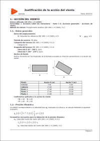
- EN 1991-1-4: 2005
Eurocode 1: Actions on structures
Part 1-4: General actions - Wind actions - prNBN EN 1991-1-4: 2005 / ANB (2009)
Annexe nationale pour la Belgique
Eurocode 1: Actions sur les structures
Partie 1-4: Actions générales - Actions du vent - CYS EN 1991-1-4: 2005 / NA (2010)
Cyprus national annex
Eurocode 1: Actions on structures
Part 1-4: General actions - Wind actions - NP EN 1991-1-4: 2005 / NA (2010)
Documento Nacional de Aplicação para Portugal
Eurocódigo 1: Acções em Estruturas
Parte 1-4: Acções Gerais - Acções do vento - SR EN 1991-1-4: 2005 / NB (2007)
Romanian national annex
Eurocode 1: Actions on structures
Part 1-4: General actions - Wind actions - SS EN 1991-1-4: 2005 / NA (2009)
Singapore national annex
Eurocode 1: Actions on structures
Part 1-4: General actions - Wind actions
This report was implemented in previous versions for other design codes and will continue to be implemented for other progressively.
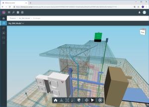
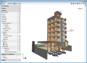
3D views
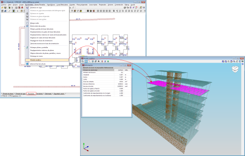
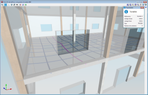
3D view of the analytical mode. New view
A 3D view of the analytical model has been included in the 2019.f version, which substitutes the old “3D model” view.
The 3D view of the analytical model can be accessed by going to the “Envelope” menu in the “Results” tab. This view is generated when the project is analysed and is always that of the last analysis.
The 3D view has an “Information” tool that is available to users (located in top left hand corner), which displays the properties of the element that users have double clicked on, in a floating window. If users carry out this selection and press the “Ctrl” key at the same time, the floating window remains on screen when another element is selected.
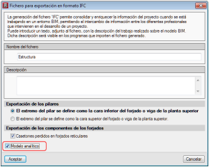
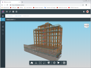
3D view of the analytical model. Export to the BIM model
If the project that is being worked on in CYPECAD is linked to an Open BIM model located on the BIMserver.center platform, the new view of the analytical model is also exported to BIMserver.center.
To do so, the “Analytical model” option must be marked in the panel that appears when the information is exported from CYPECAD to the BIM model. This way, the IFC that is generated during the export process will contain the reference to the GLTF file that contains the 3D view of the analytical model containing the information of the elements it is composed of.
Therefore, it is now possible to consult the analytical model and the physical model of the structure using the 3D viewer of the BIMserver.center platform and also from the 3D views of the rest of the applications connected to the BIM model.
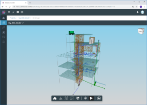
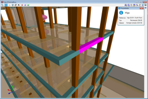
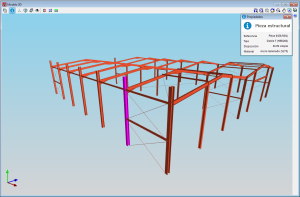
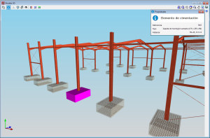
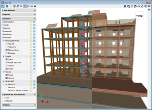
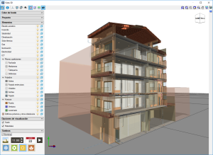
3D view of the structure. Information on the structural elements
As of the 2019.f version, users can consult the information of the structural elements introduced in the 3D view of the structure shown in CYPECAD, in the 3D view of the BIM model (GLTF) or in the 3D view of the other applications connected to the BIM project. It includes the information on slabs, beams, sloped beams, foundation elements, walls, stairs and post-tensioned tendons.
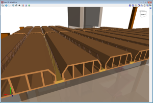
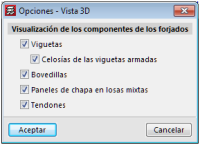
3D view of the structure. New structural elements in the 3D views (joists, forms, composite slab decks and post-tensioned tendons
The 2019.f version provides users with the possibility to include the following structural elements in the 3D view of the structure of CYPECAD and in the 3D view that is exported to the BIM model:
- Joist floor slab components: joists, joist lattice reinforcement and forms.
- Steel decks for composite slabs
- Post-tensioned tendons
To view these elements in the 3D view of CYPECAD, users must select them in the “Groups > Options - 3D View” menu. A panel appears when the export process is carried out, where users can select the elements.
Integrated 3D structures of CYPECAD
The integrated 3D structures of CYPECAD can be introduced directly in CYPECAD or imported from a CYPE 3D project.
As of previous versions, the bars of a CYPE 3D structure defined as "rectangular or circular concrete columns or beams" were imported into CYPECAD as generic bar type elements. These bars had to be redefined by users as generic concrete bars of the corresponding section so that their inertia within the integrated 3D structure of CYPECAD corresponded to reality.
As of the 2019.f version of CYPECAD, the bars of the integrated 3D structures that are present from having imported a CYPE 3D project and have been defined as "rectangular or circular concrete columns or beams" in CYPE 3D, are defined as "generic rectangular or circular concrete bars" as appropriate, in CYPECAD. This way, these bars in CYPECAD are analysed as they have been in CYPE 3D without users having to redefine the sections in CYPECAD.
CYPE 3D
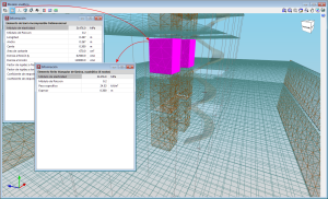
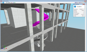
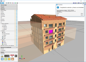
3D view of the structure. Information on the structural elements
As of the2019.f version, users can consult the information of the structural elements that have been introduced in the 3D view of the structure that is displayed in CYPE 3D.
By pressing the “Information” button of the 3D view, the elements over which the cursor is placed are highlighted in magenta and their properties are displayed.
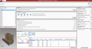
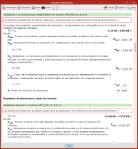
StruBIM Anchors ACI 318
Introduce load combination forces
As of the 2019.f version, users can introduce forces on the anchors that derive from several force combinations. The program evaluates them in accordance with the ACI design code (ACI 318-11 Annex D or ACI 318-14 Article 17) and provides the reports of the worst-case results.
3D view of the BIM model
As of the 2019.f version, users can view the 3D model of the BIM project for which the anchors are being analysed. The BIM project must include at least one IFC file that contains the structural model.
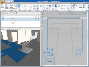
CYPECAD MEP
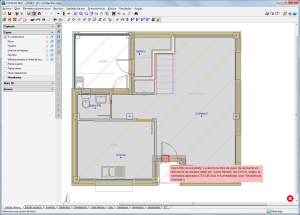
Integration in the Open BIM workflow
As of the 2019.f version, CYPECAD MEP is able to link to a BIM project located on the BIMserver.center platform and keep the BIM model up-to-date. Until now, CYPECAD MEP exported project data in files with IFC format but was not sensitive to the changes produced in the BIM project.
Now, users can view, in the 3D view, the information provided by other BIM applications that are linkedto the same project. Additionally, the program displays the requirements the project may contain and that can be resolved by CYPECAD MEP users. An example of this is the requirement concerning the free width of passage of doors located on accessible routes that are currently originated by "Open BIM Accessibility”.
More information can be found on the Requirements in the Open BIM workflow webpage.
The option “Update the BIM model” is available within the “Export” model of the CYPECAD MEP toolbar, as well as the “Export to IFC format” button.
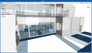
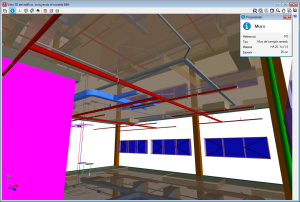
New 3D view system
As of the 2019.f version, CYPECAD MEP includes a new 3D view system.
In the previous version (2019.e), this system was already implemented for CYPE programs included in the Open BIM workflow and for CYPE 3D.
The properties of the system are:
- Improvement in the drawing speed of scenes with a large number of objects
- Dynamic analysis of the rotation pivot of the camera
- Rotation about a point indicated by users
- Possibility to define global X, Y or Z section planes
- Zoom to the object located below the cursor in the perspective and orthogonal views
- Consult information of 3D elements
As occurs in the other applications that already have this new 3D view system included, in order for the system to work, the computer video card must be compatible with OpenGL 3.3 or greater.
CYPELEC Core
Available in English
The 2019.f version of CYPELEC Core is now available in English. Please recall that CYPELEC Core can be downloaded from the BIMserver.center platform.
CYPELEC Networks
Export the circuit drawing to the BIM project
As of the 2019.f version, CYPELEC Networks allows users to export the circuit drawing to the BIM project located on BIMserver.center. This drawing includes the results of the load flow analysis and short-circuit calculations.
CYPEPLUMBING Water Systems and CYPEPLUMBING Solar Systems
DHW production systems in CYPEPLUMBING Water Systems
The 2019.f version of CYPEPLUMBING Water Systems includes new domestic hot water production systems using heat exchangers, accumulators, single or double exchange cylinders and direct or auxiliary hot water generators.
Connection between CYPEPLUMBING Water Systems and CYPEPLUMBING Solar Systems
As of the 2019.f, the devices that are introduced in CYPEPLUMBING Water Systems, and to which users assign technical characteristics related to a solar thermal installation for production of domestic hot water, are exported to the BIM project (including the calculated demand) so that CYPEPLUMBING Solar Systems can import it all. This way, CYPEPLUMBING Solar Systems users will only have to connect these devices to the solar thermal installation without having to enter them again or specify their demand.
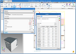
CYPEPLUMBING Sanitary Systems, CYPEPLUMBING Water Systems and CYPEPLUMBING Solar Systems
Tag configuration and personalisation of symbols
Two tabs have been incorporated in the “Representation options” dialogue:
- Tags
Allows users to configure the information included in the tags that will be introduced together with the equipment and elements of the installation. - Symbols
Allows users to create their own symbols for the elements of the installation and this way personalise the corresponding drawings.
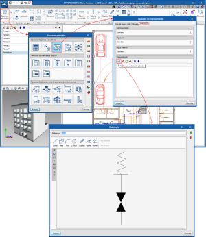
Floating toolbars
For quicker data editing and labelling of installation drawings, floating menus have been implemented for the following tools in CYPEPLUMBING Sanitary Systems, CYPEPLUMBING Water Systems and CYPEPLUMBING Solar Systems:
- Edit
- Tag
- Drawing
These floating menus can be pinned to the screen by selecting the ![]() icon located to the right of the screen header (
icon located to the right of the screen header (![]() Pinned,
Pinned, ![]() Unpinned), so they do not disappear when another tool group is activated or when the program is reopened.
Unpinned), so they do not disappear when another tool group is activated or when the program is reopened.
Furthermore, the floating menus can have three different tool views, which can be alternated using the ![]() icon located to the right of the screen header:
icon located to the right of the screen header:
- Horizontal with large icons
- Vertical with large icons
- Vertical with small icons and descriptive texts of the tools
The floating menus can also be adhered to the sides of the workspace to look like toolbars.
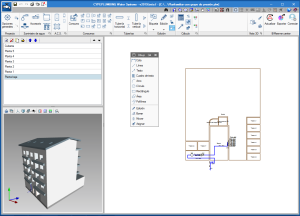
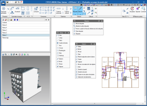
Drawing tool. Complete and add tags
The "Drawing" tool has been added in the "Edit" section of the toolbar. The "Drawing" tool includes options that already existed and new ones. With them, the user can create their own labels and edit the ones they have already entered.
Simultaneous execution of the same program with different projects
As of the 2019.f version, CYPEPLUMBING Sanitary Systems, CYPEPLUMBING Water Systems and CYPEPLUMBING Solar Systems can be opened several times with different projects. In other words, the same program can be used to work on several projects at the same time.
CYPEFIRE Sprinklers
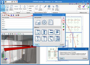
Code for Singapore (CP 52:2004)
Since its first version, CYPEFIRE Sprinklers has designed hydraulic fire extinguishing networks in accordance with the "NFPA® 13" standard (National Fire Protection Association). In the 2019.f version, the program can design in accordance with the "CP 52: 2004" standard (Singapore Standard - Code of practice for automatic fire sprinkler system). In order to be able to select one or another standard, the flags of the countries corresponding to each code have been included in the "General Options" dialogue.
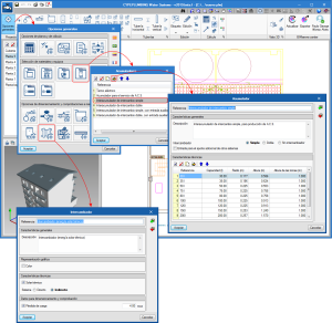
Code configuration
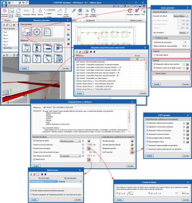
In addition to the standards configured in the program, implemented in the 2019.f version of CYPEFIRE Sprinklers is the possibility to allow users to designfire protection installations using sprinklers by customising design configurations of other standards or providing their own technical configurations. Therefore, users have the option to modify standards that are already included in the program and to introduce the regulations that they wish.
To do so, the “Specific requirements button for each space” has been added in the “General data” section of the “General options” dialogue box, which opens another dialogue with the same name.
This dialogue may contain information or may be empty:
- If a design code has been selected
If users have previously selected one of the available design codes (represented in the "General Data" box by the flag of the country to which it corresponds), the types of spaces defined in it appear and can be edited to modify them as they please. - If no design codes have been chosen
If users have not selected any design codes, the types of spaces that they deem necessary have to be included and their properties have to be defined (description, design options and sprinkler checks) in the “Specific requirements for each space” dialogue box.
The space data that is modified by users or the new data introduced can be saved and recovered in other projects using the buttons that appear below the code selection flags.
The specific requirements that can be configured for each space are:
- Reference and description
The information that defines the type of risk. - Design options
The generic minimum checks that are carried out for this type of risk are defined in the design options, such as the design density, minimum flow, minimum pressure, minimum water supply period etc. - Checks to be met by the sprinklers
The checks to be carried out on each type of sprinkler that is included in the program are specified here, such as the maximum and minimum distances between sprinklers, maximum and minimum distances between sprinklers and the wall, maximum and minimum protected areas, etc.
The “Pipes” and “Supports” sections are added in the “General data” dialogue box (“General options” > “General data”) where users can define the maximum separation between supports and the minimum allowable rod respectively.
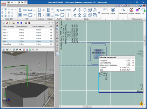
Open BIM Toshiba
Automatic generation of vertical pipes in the same floor
Users design the distribution of an air conditioning system on a plan view (2D). To do this, the equipment is arranged on plan and joined using pipes. If the height of the pipes above the floor is different from the height at which the equipment is located, vertical spans must be installed. As of the 2019.f version, the program includes these vertical spans automatically.
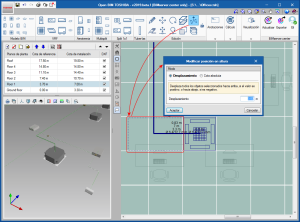
Move elements vertically
Now it is possible to move equipment and pipes vertically. To do so, use the "Modify position in height" tool and select the set of elements that are to be moved. Then, press the right mouse button and a panel will appear in which the user can choose two movement modes:
- Displacement
The group of selected objects is displaced an indicated distance, X, maintaining the elevation difference between them. - Absolute elevation
All the selected objects are placed at the indicated absolute elevation.
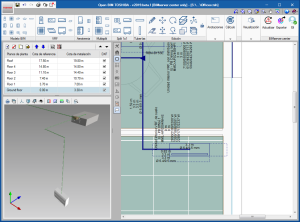
View the number of pipes in real scale in the 2D and 3D views
Once the installation is analysed, the program represents the 2 or 3 pipes (depending on the system) on real scale in the 2D view of the workspace and the 3D view.
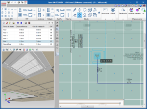
Cassettes in suspended ceilings
The program imports the suspended ceilings included in "Open BIM Suspended Ceilings" from the BIM model. These can be seen in the 3D view and in the 2D view of Open BIM TOSHIBA, and when a cassette machine is introduced, it is automatically placed at the height of the suspended ceiling.
CYPETHERM Schematics and CYPETHERM Radiant floor
Name change
The names of CYPETHERM Schematics and CYPETHERM Radiant floor have been changed to "CYPEHVAC Schematics" and "CYPEHVAC Radiant Floor", respectively.
The prefix CYPEHVAC is a better representation of the performance of these programs,which, although they may need a previous thermal analysis, are really related to the design of HVAC equipment (CYPEHVAC Schematics draws hydronic air conditioning systems principle circuits and CYPEHVAC Radiant Floor carried out the calculation of air conditioning systems with radiant floor heating systems).
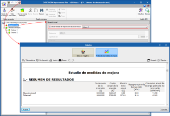
CYPETHERM Improvements Plus
Establish an improvement measure as initial situation
A new option: "Use improvement measure as initial situation"has been added in the "Initial Situation" definition panel. This implies that wheneconomic and energy comparisonsare made, the data of the selected measure, including its costs, will be taken as the reference. This way, the scope of the program is extended to the study of alternatives for new projects, in which there is no initial situation.
CYPETHERM programs with the EnergyPlusTM analysis engine (CYPETHERM EPlus and CYPETHERM RECS Plus)
Reduction in the analysis duration
Improvements have been implemented in the simplification of the 3D thermal model, which entail a significant reduction in the time required to analyse the project. As in previous versions, the simulation with the simplified building is carried outby choosing the "Simplification of the vertical partitions" options within the design options.
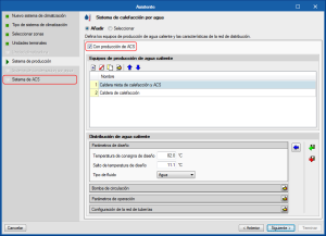
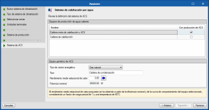
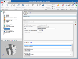
Definition of mixed equipment for heating and DHW using an assistant
The "Assistant for the definition of air conditioning systems" includes the "With the production of DHW" option for hot water generation equipment and systems.
When this option is activated, the step: “DHW system” appears in thein the index sequence of the assistant. Upon reaching this step, the assistant shows the operating characteristics for DHW production of the previously defined hot water production equipment. In the case of water heating systems, the user must choose a boiler that will produce the DHW. The properties of the panel are recalculated automatically.
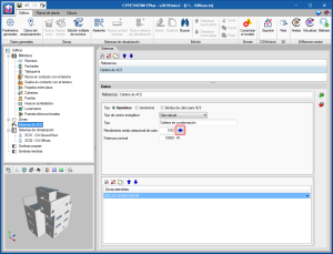
Users can edit the values proposed by the assistant if he has more precise data, and even use the new assistant to calculate the average seasonal boiler performance (blue arrow icon). At the end of the assistant sequence, an ACS system with the characteristics of the defined equipment will be created automatically. The configuration of the DHW system that has been created by the assistant depends on the option that has been selected previously in the "Daily DHW Demand" in the “General Parameters”. If "Total demand of the building" has been selected, a single DHW system will be created that supplies the entire building, regardless of the number of production systems that have been created with the assistant. On the other hand, if "Demand by zones" has been selected, a DHW system will be created that serves the same zones as the defined air conditioning system using how water. With this option activated, if the option "Add a production system by zone" is selected in the assistant, the corresponding ACS system by zone will be created.
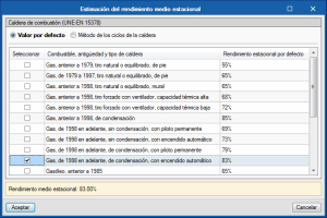
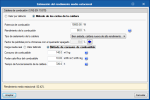
Estimate of the average seasonal performance of boilers for DHW production
An assistant has been addedin generic DHW systems to calculate and import the value of the average seasonal performance of combustion boilers according to the UNE-EN 15378 standard. Two of the methodologies included in the standard have been implemented. On one hand, users can choose a value of the average seasonal performance by default, which depends on the fuel, age and type of boiler (Table B.3 UNE-EN 15378). On the other hand, the boiler cycle method (Annex N UNE-EN 15378), can be chosen, which provides a more accurate estimate if technical and equipment consumption data is available.
Ventilation via air conditioning systems
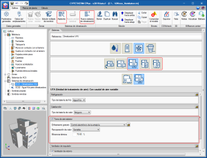
The option "External air intake" has been addedfor "Variable air flow" and "Double duct"air conditioning systems. Free cooling, and sensitive or enthalpy heat recovery energy saving strategies can be applied when air can be taken from outside using these systems.
Adding an air conditioning system with external air intake implies that the air impulse terminal units connected to the system will perform the ventilation of the zones where they are defined. Therefore, for these areas, the Ventilation optionmust be chosenvia the air conditioning system. This option is activated automatically when this type of system is created using the assistant.
Unknown adjacent spaces
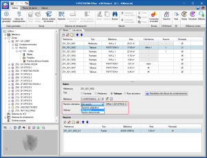
For each space, the walls and slabs that limit it are defined. When one of these elements is an interior partition, i.e., a partition or a floor between floors, the space that lies on the other sidemust be defined. Until now, users could choose an adjacent room amongst those defined in the project or leave this field empty, which implied that the partition is adiabatic, that is, no heat is lost or gained through it.
In the 2019.f version, the definition of the existing options is explicitly indicated in "Adjacentspace" and the new option "Unknown space" has been added. This option allows users to more adequately define the partitions that are next to spaces of other buildings, whose use is unknown and have not been defined in the project. For design purposes, this unknown space will have the outside temperature.
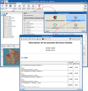
Report of linear thermal bridges
In the "Calculation" tab, within "Complementary reports", the report "Linear thermal bridges" has been implemented. This report includes the total length and the linear thermal transmittance (value Ψ) of the thermal bridges defined in the project.
Import Daikin Open BIM equipment
CYPETHERM programs with the EnergyPlusTM analysis engine, CYPETHERM EPlus and CYPETHERM RECS Plus, can import the equipment and pipes introduced in "Open BIM DAIKIN" (implemented in this version) if they are connected to a BIM project located on the BIMserver.center platform that contains this information.
Arquimedes
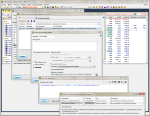
More functions to calculate the value of user columns
The features of user columns are extended with two new functions when defining calculation expressions in calculated user columns:
- COLUSR_TIP(n)
Indicates the type of data contained in the cells of the user column represented by the parameter "n" (with a value between 1 and 15). The return value is "0" (contains text) or "1" (contains a numeric value). - COLUSR_VAL(n)
Returns the numerical value contained in the cell of the user column indicated by the parameter "n" (with value between 1 and 15). If the value of parameter 'n' is out of range, an error will occur and the text "Error" will be displayed in the cells of the column.
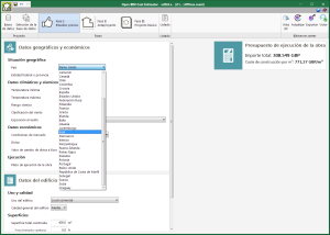
Open BIM Cost Estimator
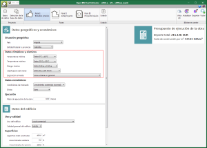
Climate and seismic data
As of the 2019.f version, Open BIM Cost Estimator contemplates the climate and seismic data that affects the budget of the building. These factors are the following:
- Thermal conditions
The outdoor temperature affect the design and parameters of the envelope and thermal installations of the building, especially the cost of the insulations and the exterior carpentry. - Wind intensity
The dynamic pressure of the wind conditions the design, parameters and cost of the structure and exterior carpentry. - Wind exposure grade
Affects the cost of the structure and exterior carpentry, especially in buildings located near cliffs, the seaside and rural areas without obstacles, amongst others. - Seismic risk
Seismic action influence the design of the foundation and the structure, and therefore, affect the final cost of the building.
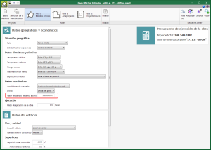
Edit the currency exchange value
As of the 2019.f version, the exchange value of the currency used in the project can be changed to Euros.
Open BIM Cost Estimator includes the exchange values for the currencies corresponding to the countries that are contemplated in the application. However, due to the volatility of some currencies and the difficulty to keep them updated, we have considered it would convenient for the user to have the possibility to controlthis factor directly.
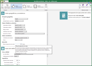
Help
Help texts have been added in the different input parameters of the application to help users interpret the parameters correctly.
New countries
Mali and Cape Verde, together with their respective federal entities or provinces, have been added to the list of countries that can be selected within the geographical configuration of the project (Phase I: Previous studies). Open BIM Cost Estimator uses the location of the project to determine the geographic and socioeconomic factors that will be applied to the prices used to elaborate the budget.
Return to the 2019 version download area
Tel. USA (+1) 202 569 8902 // UK (+44) 20 3608 1448 // Spain (+34) 965 922 550 - Fax (+34) 965 124 950