- New modules and programs
- Improvements in code application
- Open BIM Carpentry
- CYPECAD
- CYPECAD, CYPE 3D and Continuous beams
- CYPELEC Networks
- CYPEPLUMBING Sanitary Systems
- CYPEPLUMBING Water Systems
- CYPEPLUMBING Solar Systems
- Automatic adjustment of the solar collector to the geometry of the roof
- Graphical analysis of the installation
- Height of the installation by floor
- Improved layer management in 2D and 3D views
- Improvements in drawings keys
- Move vertical pipes
- Move installation elements
- Rotate tags
- Shortcuts to general options
- CYPEFIRE Design
- CYPEFIRE Sprinklers
- CYPETHERM Programs with EnergyPlusTM analysis engine (CYPETHERM EPlus and CYPETHERM RECS Plus)
- Arquimedes and Job control
- Return to the 2019 version download area
New modules and programs
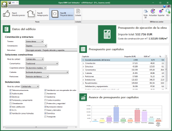
Open BIM Cost Estimator
Open BIM Cost Estimator has been conceived to carry out an automatic estimate of the execution budget of a building project during the preliminary phases of the architectural project, in a simple and practical way, using a fast, efficient and precise analysis model, which contemplates the built surface, the height of the building, and typological, constructive, geographic and socioeconomic factors.
The user license permits that are required to work with “Open BIM Cost Estimator” depend on the value of the execution budget that has been calculated by the program:
- Up to 1,000,000 €
The program is free. - Up to 5,000,000 €
The user license must include the Open BIM Cost Estimator Pro permit. - Over 5,000,000 €
The user license must include the Open BIM Cost Estimator Expert permit.
Open BIM Cost Estimator can be downloaded from the BIMserver.center platform.
Open BIM Cost Estimator is included in the Open BIM workflow. The program reads the geometry of the building from the project BIM model to show its 3D view and exports the execution budget of the project to the BIM model (in pdf format) and the documents that are required to be used by “Open BIM Memorias CTE”.
More information on this new CYPE tool will be available shortly.
Improvements in code application
Loads on structures. Wind loads
CIRSOC 102-2005 and ASCE/SEI 7-05
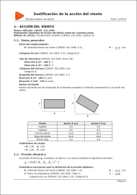
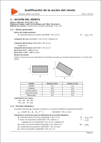
The improvements that have been implemented in the application of these codes can be seen in the “Justification report of the wind loads in accordance with CIRSOC 102-2005 and ASCE/SEI 7-05” section of the new features of CYPECAD on this webpage.
Open BIM Carpentry
New window-type design options
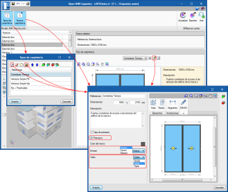
The 2019.d version of Open BIM Carpentry contains more options to define different types of windows:
- Subframe
It is possible to select whether the glazed opening has a subframe. - Number of panes
Users can choose amongst single, double or triple glazing. - Location of the window with respect to the wall
Users can select whether the window is at the same level as the outer or inner part of the wall or centred.
These properties allow users to provide a more complete specification of the windows and obtain a more precise budget.
Improvements in the 3D views of the windows
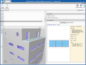
The 3D representation of the windows has been improved in the 3D views of the Open BIM applications that access the project as well as in the GLTF format that Open BIM Carpentry exports to the Open BIM project.
It is more realistic thanks to the new design options that have been implemented:
- The window is represented at the correct level with respect to the wall.
- The size of the frame varies depending on the type of glazing (number of panes of glass).
- Handles are displayed.
CYPECAD
Column groups
Activate/deactivate automatic column groups
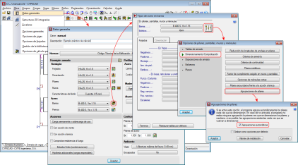
Up until the 2019.d version, the program automatically grouped columns that had the same reinforcement and geometry each time they were designed. With the 2019.d version, the columns can be designed without them being grouped automatically. To do so, the “Automatic groups” option has been implemented (Project > General data > “By position” button > “Options for columns, shear walls, walls and corbels” > “Design/Code checks” > “Column groups”).
The “Column groups” option is active by default, and so the program will operate as it has been doing so until now regarding the column groups, i.e. automatically grouping them each time they are designed.
If the option is deactivated, the program will no longer group them automatically. In this case, the first time they are defined, all the columns will appear ungrouped. The program will never modify column groups that users have defined, even if this option has been deactivated, unless the columns have undergone changes in their dimensions, rotations, floor groups they go through, etc.
Undo column groups
A new option, “Ungroup all”, has been included in the column schedule. This option ungroups all the columns, leaving each column as an individual group.
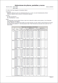
Shear walls in the “Distortions report”
As of the 2019.d version, the distortions report also includes the results of the shear walls, besides those of the columns and walls.
Before the 2019.a version, this report only contained the results for columns. As of the 2019.d version, walls were added to the distortions reports, and now, the three types of supports are included (columns, shear walls and walls).
Justification report of the wind loads in accordance with CIRSOC 102-2005 and ASCE/SEI 7-05
New for the 2019.d version is the “Wind loads justification report” for CIRSOC 102-2005 (Reglamento Argentino de Acción del Viento sobre las Construcciones) and ASCE/SEI 7-05 (Minimum Design Loads for Buildings and other Structures).
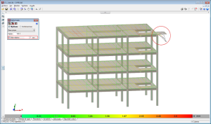
Maximum limit for the view of the values of the deformed shape
As of the 2019.d version, users can establish a displacement limit as of which the values of the deformed shape are not displayed.
In other words, the deformed shaped of the structure is still represented with the scale factor that users have specified regardless of whether the indicated limit has been exceeded or not. What happens now is that the points that exceed the displacement limit are displayed in black.
To do so, the “Maximum value” option has been included in the “Deformed shape” panel that is represented in the “Deformed shape” tab.
This tool helps users to view the values of the deformed shape, discarding the parts with a displacement value that is greater than that established by users.
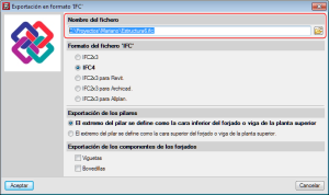
Export path of the IFC file
In previous versions, each time a file was exported to IFC format, the program would propose a default path: “C:\CYPE Ingenieros\Export files\CYPECAD\**.ifc”. As of the 2019.d version, the program remembers the path to which the file was exported previously, even if it belongs to a different project.
CYPECAD, CYPE 3D and Continuous beams
Calculation of the differed deflection of concrete beams
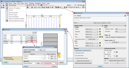
As of the 2019.d version, CYPECAD, CYPE 3D and Continuous beams allow users to edit the percentage of live load to be considered as quasi-permanent load to take it into account when calculating the differed deflection. To do so, the “Construction process” panel has been included in the “% Quasi-permanent” field. The panel can be accessed as follows:
- CYPECAD
In CYPECAD, users can indicate a different live load percentage as quasi-permanent load for each floor group:
Project > General data > Permanent and live load > “Edit” button of the floor in question. - CYPE 3D
Project > General data > Construction process - Continuous beams
General data > Construction process
CYPELEC Networks
French, Italian and Portuguese versions
CYPELEC Networks has been translated into French, Italian and Portuguese, hence, once downloaded from the BIMserver.center platform, the program can be installed in these languages, as well as in English or Spanish, which were available when the program was launched.
CYPEPLUMBING Sanitary Systems
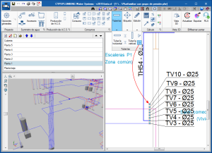
Move drainpipes
A new icon  has been added to the “Pipes” toolbar, which users can use to completely move a drainpipe, from its initial floor to the last. In previous versions, they could only be moved using the generic “Move” tool
  from the “Edit” menu, which continues to exist to move any element. However, when this tool is used to move drainpipes, only the span of the pipe of the floor that is shown on-screen is moved.
In both cases, only the drainpipe is moved and not the horizontal pipes that connect to it.
The tool to move complete vertical drainpipes ( ) has also been implemented in CYPEPLUMBING Water Systems and CYPEPLUMBING Solar Systems.
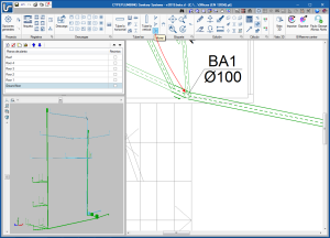
Rotate tags
Tag management in drawings has been improved. Now, tags follow pipes or their associated element when they are moved.
Additionally, the tool “Rotate tag”  has been added in the “Label” menu.
The same tool has been added in CYPEPLUMBING Solar Systems.
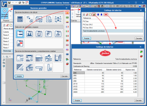
JIMTEM “dBlue” pipes catalogue
The pipes library now incorporates JIMTEM’s “dBlue” pipes catalogue. The catalogue that has been introduced includes soundproof evacuation pipes of up to 10dB at 2 l/s and are manufactured using PPMD.
This catalogue is available in the library and can be used when the code that has been selected in the “General options” dialogue box is the “HS 5 Evacuación de aguas” code (Spain). If a different code or country is selected, JIMTEN’s “dBlue” catalogue is not imported automatically, but users can import it by selecting the JIMTEN logo in the “Pipes catalogue” panel.
CYPEPLUMBING Water Systems
Move vertical pipes
A new icon  has been added to the “Pipes” toolbar, which users can use to completely move a drainpipe, from its initial floor to the last. In previous versions, they could only be moved using the generic “Move” tool
  from the “Edit” menu, which continues to exist to move any element. However, when this tool is used to move drainpipes, only the span of the pipe of the floor that is shown on-screen is moved.
In both cases, only the drainpipe is moved and not the horizontal pipes that connect to it.
The tool to move complete vertical drainpipes ( ) has also been implemented in CYPEPLUMBING Sanitary Systems and CYPEPLUMBING Solar Systems.
Move installation elements
As of the 2019.d version of “CYPEPLUMBING Water Systems”, when users move elements of the installation, they are not disconnected from it.
This improvement has also been implemented in CYPEPLUMBING Solar Systems.
Manage tags
Tag management in drawings has been improved. Now, tags follow pipes or their associated element when they are moved.
Additionally, users can insert a tag using the “Insert text” tool  in the “Label” menu. Inserted tags will not be associated to elements or pipes of the installation.
Pipe elevation warnings
When the elevations of horizontal pipes lie outside the top or bottom elevations of the floor, the program emits a warning.
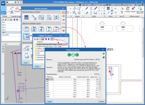
AQUATHERM “Green Pipe” pipes catalogue
The pipes library now incorporates AQUATHERM’s “Green Pipe MF RP [Series 4 / SDR 9]” and “Green Pipe [Series 5 / SDR 11]” pipes catalogues.
These catalogues is available in the library and can be used when the code that has been selected in the “General options” dialogue box is the “HS 5 Evacuación de aguas” code (Spain). If a different code or country is selected, AQUATHERM’s “Green Pipe” catalogue is not imported automatically, but users can import it by selecting the AQUATHERM logo in the “Pipes catalogue” panel.
CYPEPLUMBING Solar Systems
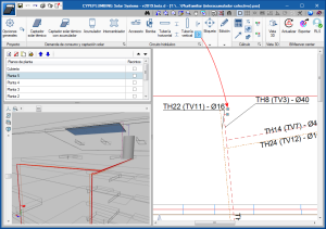
Automatic adjustment of the solar collector to the geometry of the roof
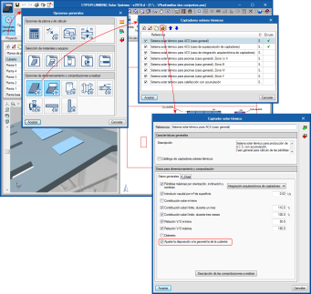
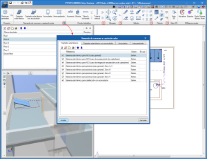
In the 2019.d version of CYPEPLUMBING Solar Systems, the option: “Adjust the layout to the geometry of the roof” has been implemented for solar collectors (“General settings” button > “Design and check options to be carried out” section > “Solar thermal collectors” or “Solar thermal collectors with storage tanks” button > Edit or create a collector).
The option “Adjust the layout to the geometry of the roof” is activated or deactivated independently for each type of solar collector that has been defined in the general options.
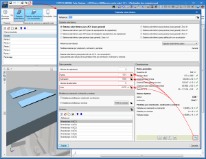
If the option “Adjust the layout to the geometry of the roof” is activated, the program will automatically adjust the solar collector (azimuth, slope and installation height) to that of the geometry of the roof when users select the “Design” button in the panel that appears when a solar collector is introduced or edited.
If the option “Adjust the layout to the geometry of the roof” is not activated, the program will only adjust the azimuth and the slope to its optimum values (regardless of the geometry of the roof) when users select the “Design” button from the panel that appears when a solar collector is introduced or edited.
Graphical analysis of the installation
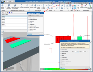
In the 2019.d version, the program allows users to select the parameters that intervene in the calculation of the demand, solar contribution and hydraulic calculations of the installation that are to be analysed, and draws the installation using a colour scale  to ease its graphical analysis in the 2D and 3D views on screen. The parameters to be analysed are selected in the dialogue box that appears when the button, that is located in the “Calculation” section of the toolbar is pressed.
Specific result ranges can also be studied in the global scope of the installation by selecting the  button in the same section.
Height of the installation by floor
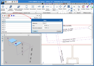
In the 2019.d version, users can indicate the height at which the general pipe installation is to be placed. This height can be indicated when the floors are edited.
Improved layer management in 2D and 3D views
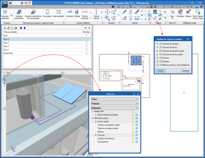
In the 2D view of CYPEPLUMBING Solar Systems, circuits can now be viewed by layer.
Furthermore, the management of the layers in the 3D views has been improved; the layers of the discharge and return circuits have been separated.
Improvements in drawings keys
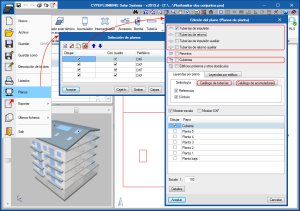
As of the 2019.d version, drawings by circuit can be chosen (Discharge pipes, Return pipes, Auxiliary discharge pipes and Roofs) in the “Edit drawings (Floor plans)” dialogue box. Furthermore, users can design the catalogue keys of the pipes and storage tanks.
Move vertical pipes
A new icon  has been added to the “Pipes” toolbar, which users can use to completely move a drainpipe, from its initial floor to the last. In previous versions, they could only be moved using the generic “Move” tool
  from the “Edit” menu, which continues to exist to move any element. However, when this tool is used to move drainpipes, only the span of the pipe of the floor that is shown on-screen is moved.
In both cases, only the drainpipe is moved and not the horizontal pipes that connect to it.
The tool to move complete vertical drainpipes ( ) has also been implemented in CYPEPLUMBING Sanitary Systems and CYPEPLUMBING Water Systems.
Move installation elements
As of the 2019.d version of “CYPEPLUMBING Solar Systems”, when users move elements of the installation, they are not disconnected from it.
This improvement has also been implemented in CYPEPLUMBING Water Systems.
Rotate tags
Tag management in drawings has been improved. Now, tags follow pipes or their associated element when they are moved.
Additionally, the tool “Rotate tag”  has been added in the “Label” menu.
The same tool has been added in CYPEPLUMBING Sanitary Systems.
Shortcuts to general options
Shortcuts  to the “General options” have been added in the following sections of the top toolbar:
- Consumption and solar collection demand
- Hydraulic circuit
- Tag
- Edit
- Analysis
CYPEFIRE Design
Definition of the checks for evacuation paths
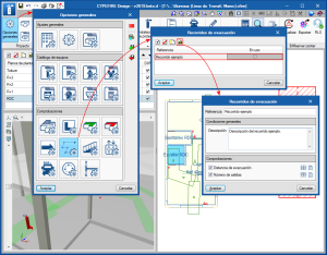
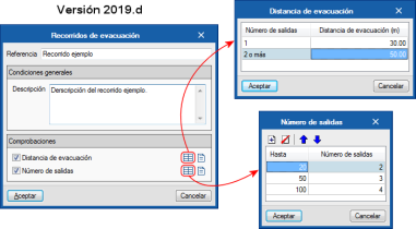
In the 2019.d version of CYPEFIRE Design, the way in which the checks of the Evacuation paths are defined has been changed (Evacuation distances and Number of exits).
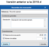
In previous versions, a minimum distance and number of exits were defined, and so, different checks with different properties have to be defined for each path.
As of the 2019.d version, the evacuation distance is defined depending on the number of exits that are detected for each evacuation path and the number of exits depending on the occupancy that circulates along each path.
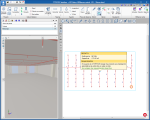
The image shows two different minimum evacuation distances; one for paths with a single evacuation exit and another for paths with 2 or more exits. It is also possible to see how a different number of exits has been defined depending on the occupancy.
This new way to define the checks allows users to edit them more quickly. Multiple checks no longer have to be defined for different paths because now a single check can apply different minimum values depending on the properties of the path that is being analysed.
CYPEFIRE Sprinklers
“Aquatherm Red Pipe” pipes catalogue
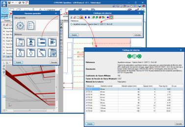
The 2019.d version of CYPEFIRE Sprinklers now includes Aquatherm’s “Aquatherm Red Pipe” catalogue in its pipes library.
The catalogue that has been introduced for the design is that of Aquatherm Red Pipe fire safety pipes, which consist of polypropylene random copolymer pipes, with an intermediate fibreglass layer, with a fire reaction classification, in accordance with UNE EN 1351-1, B s1 d0, red with green strips, manufactured in accordance with UNE EN-ISO 15874, with Technical Suitability Evaluation, in accordance with the “Reglamento de Instalaciones de Protección contra Incendios” RIPCI 2017, and homologated, amongst others, by FM, Technical Suitability Documents DIT 618/15 for installation with automatic sprinklers and DIT 617/15 for fire hose reels.
The Aquatherm catalogue can be incorporated into the project by selecting the Aquatherm logo located in the top part of the “Pipes catalogue” panel, and the import is carried out in the same way as for the other catalogues. Once imported, the data cannot be edited, as is done with the generic pipes catalogues, but their properties can be seen.
Design method. Selection of the equation to calculate the pressure loss
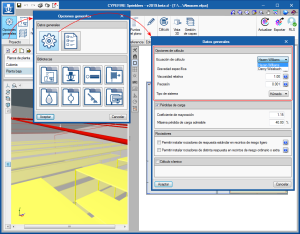
The 2019.d version of CYPEFIRE Sprinklers allows users to select the pressure loss equation, either the “Hazen-Williams” or “Darcy-Weisbach” method, to apply when the sprinkler installation is analysed.
Upon selecting the pressure loss equation, other properties are defined, such as:
- Specific gravity
Ratio of the density of the fluid with respect to that of water at 4°C. - Relative viscosity
Ratio of the kinematic viscosity of the fluid with respect to that of water at 20°C. - Precision
Convergence criteria used to indicate that the solution to the non-linear equation has been found. The iterations end when the sum of all the changing flows divided by the sum of all the line flows is less than this number.
The Hazen-Williams analysis method is one of the most used methods due to its simplicity, but cannot be used for liquids other than water. The Darcy-Weisbach method, however, is more precise but more complex, because the friction factor has to be calculated. All these options can be edited and are located in the “General data” panel.
Notification of the requirement to have an automatic fire extinguishing installation
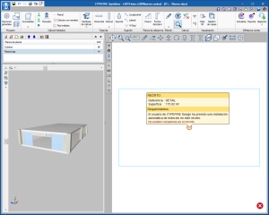
The way in which the requirements of an automatic fire extinguishing installation are notified for projects coming from CYPEFIRE Design and CYPEFIRE CTE has been updated.
Now, when users have defined a sprinkler installation in the previously mentioned applications, but it has not been defined in CYPEFIRE Sprinklers, an error will appear in the space in which it is lacking, warning of its inexistence and the program that has foreseen it.
When CYPEFIRE Sprinkler users introduce the automatic extinguishing installation, the error message, although in the information of the space, the program that has foreseen the requirement remains and informs the user whether it has been fulfilled.
CYPETHERM Programs with EnergyPlusTM analysis engine (CYPETHERM EPlus and CYPETHERM RECS Plus)
Weather conditions to calculate the SPF of the heat pumps (Improvement of the analysis model of Daikin hot water systems)
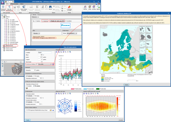
In the “Location data” panel, it is possible to select the climatic conditions to calculate the seasonal performance factor (SPF) of the heat pumps, in accordance with Commission Decision 2013/114 / EU, which applies Article 5 of the European Directive 2009/28/EC. According to the EN 16147 standard, these climatic conditions are also applicable when calculating the seasonal coefficient of performance of heat pumps for DHW production “SCOP (DHW)".
Daikin has supplied this coefficient, providing CYPETHERM EPlus with an improved design model of Daikin's DHW systems (aerothermal and heat pump for DHW) by distinguishing between these climate conditions to determine the corresponding value of "SCOP (DHW)" according to the EN 16147 standard.
CYPETHERM RECS Plus also includes this improvement. Although it does not include the possibility of selecting the SPF climate conditions (since Portugal only has warm weather according to Commission Decision 2013/114/EU), the "SCOP (DHW)" value of Daikin's DHW systems (aerothermal and heat pumps for DHW) of CYPETHERM RECS Plus, corresponds to the warm climate zone.
Daikin Altherma Flex aerothermal system
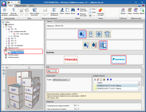
The 2019.d version includes Daikin's "Altherma Flex" range in "Aerothermal-type water-conditioning systems" and "Aerotermal-type DHW systems". The equipment of this range only produce hot water, for heating and/or DHW.
In "Aerothermal-type air conditioning systems", users can choose amongst different indoor and outdoor unit models of the Flex series. This range allows for several indoor units to be connected to a single outdoor unit, as long as the total power of the indoor units lies between 50% and 130% of the power of the outdoor unit.
The Altherma Flex aerothermal equipment must be connected to radiator-type or radiant-floor water conditioning terminal units.
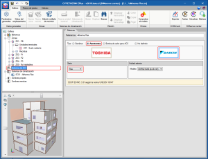
The Altherma Flex range is also available within "Aerothermal-type DHW systems". As with the rest of the aerothermal equipment, if users wish to use an Altherma Flex unit for heating and DHW, the same outdoor unit model must be selected in both sections.
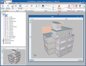
3D view to complete screen
The "3D View" button has been added in the toolbar of the "Building" tab. Users can view, in a new window and in full screen, the 3D view of the BIM model of the building.
From previous versions, the 3D view of the BIM model is also shown in the lower left corner of the screen although it cannot be extended to full screen. The configuration of both 3D views (perspective, elements that are displayed, display mode ...) is independent.
Arquimedes and Job control
Configuration of automatic backups
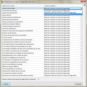
Since previous versions, Arquimedes carries out automatic backups every so often (users can configure this period in File > Preferences > Auto-save time), or when specific processes are carried out (change of currency, price increases, budget adjustment...). As of the 2019.d version, users can configure the automatic backup procedure of these processes.
To do so, the “Automatic backup configuration” panel has been created: File > Preferences > Automatic backup configuration. Users can also use the “Automatic copies” button of the “Processes > Safety copies of the database” menu.
In the new panel (Automatic backup configuration), the options that can be configured for each process are:
- Always create a backup
- Do not create a backup
- Ask before creating a backup
The maximum number of backup copies that are to be kept can also be indicated in the same panel.
The way in which the automatic backups are configured is important, especially, when the database contains a lot of information because each backup can take up a significant amount of space in the storage device.
Bill of quantities of Revit models
Configuration of the Job item assignment dialogue and quantity extraction from the Revit model
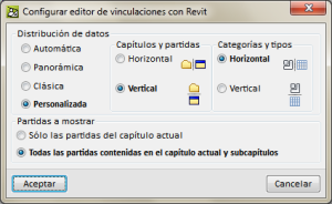
The 2019.d version of Arquimedes allows users to configure the view of the “Job item assignment and quantity extraction” panel, to help them with the Revit model connection process in accordance with its preferences or types of monitors.
To access the configuration of the Revit links editor, the button  must be selected (quantity extraction) that is present in the Decomposition tree window, and choose the “Configure Revit links editor” option.
Users can choose amongst 4 types of views:
- Automatic
This is the option that is active by default. With it, the data distribution that will be shown in the “Job item assignment and quantity extraction” panel will depend on the type of format of the monitor that is being used (width to height ratio). - Panoramic
- Classic
- Personalised
Using this type of view, users decide how to distribute the data of the “Job item assignment and quantity extraction” panel.
Quantities from Revit models and other linked Revit models
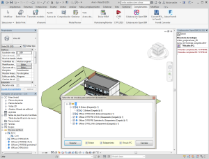
A Revit model can have links to other Revit models. As of the 2019.d version, Arquimedes can extract the quantities of Revit models that are linked to the main or central Revit model.
Arquimedes users can select the linked models whose quantities are to be extracted. The program will request the selection of links to extract the quantities (as can be seen in the attached image), when a Revit project has been linked with an Arquimedes project or when a quantities extraction file (mcsv) has been generated.
As of previous versions, if there is already a link between the Arquimedes project and the Revit project (or if a quantities extraction file of a Revit project has been generated), when the process is carried out again, a panel appears that allows the two links (or extractions) to be compared. As of the 2019.d version, this comparison includes the quantities of the Revit models that have been linked to the main Revit model.
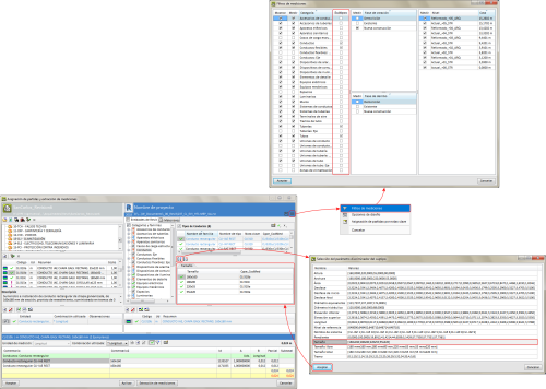
Filter to measure duct, pipe, tube...subtypes
Quantities of “Ducts”, “Pipes”, “Tubes”, etc., categories can be measured more easily using the subtype filter.
As of the 2019.d version, users can define a subtype by indicating a discriminating parameter, to link its contents by grouping them in groups that share the same value for that parameter.
To add a subtype, users must tell the BIM model that is linked to the Revit project, which Subtypes are to be measured. This can be done by pressing the  button and selecting the “Quantity filters” option. In the “Subtypes” column (implemented in this version), the program, by default, predefines filters for “Ducts”, “Flexible ducts”, “Pipes” and “Tubes” categories, if the Revit model contains them. Users can select other subtypes to filter.
Once the “subtype filters” have been established for the types of categories to be measured, a discriminating parameter must be added in the category by pressing on the New subtype button  . The list will show the parameters of the category and only those with more than one value are included.
Once a parameter is selected, having pressed the Accept button, a subtype will become associated to a parameter, which can then be linked to a job item of the bill of quantities to carry out the quantity extraction.
If a type already contains links to several job items of the bill of quantities, these links can be reused, as long as they use the same filter based on the same parameter. To do so, simply press the Add new subtype button. Otherwise, if the type is linked to a single job item, all the links to job items must first be eliminated to be able to define a subtype.
Export the “Floors” and “Ceilings” categories of the “Rooms”
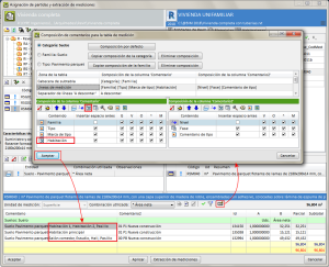
The information on rooms that use the “Floors” and “Ceilings” categories has been incorporated to the data of BIM model in Revit that is exported to Arquimedes. This way Arquimedes can indicate in the comments section of the quantity tables of the room that a specific floor or ceiling is used.
To compose the connects of the quantity lines in the quantity extraction process, having added a job item of the bill of quantities to a type of the BIM model, the “Comments composition” button  , in the quantities table, must be selected, and add the element “Room”
  to the Category, Family, or Type.
To establish whether an element belongs to a specific room, the element must be defined in or in contact with the correspondent room.
Return to the 2019 version download area
Tel. USA (+1) 202 569 8902 // UK (+44) 20 3608 1448 // Spain (+34) 965 922 550 - Fax (+34) 965 124 950
