- New modules and programs
- Open BIM Suspended Ceilings
- CYPECAD
- StruBIM Anchors ACI 318
- CYPELEC Networks, CYPELEC Core, CYPELEC NF and CYPELEC REBT
- CYPELEC Core, CYPELEC NF and CYPELEC REBT
- CYPELEC Core and CYPELEC REBT
- CYPELEC Core
- CYPETHERM LOADS
- CYPETHERM programs with EnergyPlusTM analysis motor (CYPETHERM EPlus and CYPETHERM RECS Plus)
- CYPETHERM HVAC
- Arquimedes and Job control
- Return to the 2019 version download area
New modules and programs
Open BIM Systems
Open BIM Carpentry
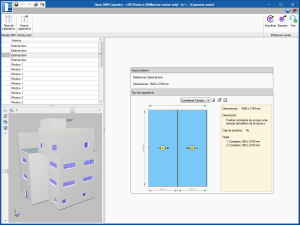
Open BIM Carpentry is a program that has been created to help users to design and create the documentation of the carpentry of a building. In its initial versions, Open BIM Carpentry allows users to specify the design of exterior glazed windows and doors and obtain the corresponding drawings and documents with the specifications that are required for the development of the project.
Open BIM Carpentry is integrated in the Open BIM workflow using the IFC standard and can be downloaded from the BIMserver.center platform.
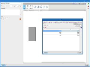
This integration allows Open BIM Carpentry to read the glazed openings of the BIM model that will be used as a reference by users to introduce and design the glazed doors and windows. The program allows users to define the types of windows and doors by specifying the type of sheet/pane, the opening system, the size and layout of the opening and blind box.
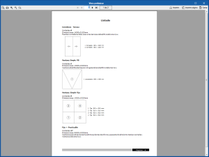
Open BIM carpentry generates a report that contains the necessary information on the breakdown of the windows and doors, and is exported to the BIM model as an attached document in PDF format, which can be used to complete the execution project.
Open BIM Carpentry also exports the 3D geometry of the designed elements to the BIM model located on the BIMserver.centerweb platform. This way, they can be viewed in the 3D views of any of the specialist programs participating in the BIM project and in the 3D viewer of the BIMserver.center platform from mobile devices, tablets, computers...
Users must have the corresponding user license permit to be able to work with “Open BIM Carpentry”.
More information on this new CYPE program will be available shortly.
Open BIM Accessibility
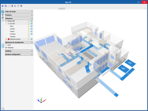
Open BIM Accessibility is a program that allows users to check the accessibility requirements of a building.
In its first version, the program checks section "SUA 9 Accessibility" of the "Basic Document Security of use and accessibility" of the "Technical Building Code" (Spain). In future versions, the program will check other standards by editing the check parameters.
Nonetheless, Open BIM Accessibility also allows users to modify the requirements included in the program to contemplate those of other state, regional or local standards.
This application is integrated in the Open BIM workflow using the IFC standard and can be downloaded from the BIMserver.center platform.
The normal way of working with the program requires for the project to be connected to a BIM project located on the BIMserver.center platform that includes the architectural model (generated by CAD/BIM programs such as IFC Builder - free CYPE program-, Allplan, Archicad or Revit) from which all the necessary accessibility requirements are defined.
Nonetheless, an empty BIM project can be created with the program, in which the floor levels can be defined and then include the necessary accessibility requirements using DXF templates that the program can import.
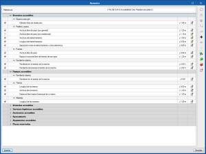
With Open BIM Accessibility, users can define:
- Accessible use units
Spaces in which accessibility requirements must be met and have special necessities (toilets, homes, lodgings...). - Access paths
The path a user in a wheelchair must follow from outside the building and inside it can be indicated. - Access ramps
Allows users to indicate how elevation level differences are treated. - Accessibility elements
Accessible lifts, accessibility signs, accessible car park, opening mechanisms, etc. - Transfer spaces
Control of transfer spaces from accessibility elements to the wheelchairs.
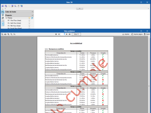
Open BIM Accessibility generates drawings and documents in accordance with the requirements of CTE DB SUA 9. These documents are also exported to the BIM model.
The 3D graphical documentation is visible in the 3D views of the BIMserver.center platform viewer or from any of the specialist programs that collaborate with the project.
Furthermore, the documents that justify the requirements of the CTE DB SUA 9 are met, are imported by “Open BIM Memorias CTE” to then elaborate the “Cumplimiento del CTE (Accesibilidad)” document that is needed for the project.
To be able to work with “Open BIM Accessibility”, users must have the corresponding permits in their user license.
More information on this new CYPE program will be available shortly.
MEP
CYPEPLUMBING Solar Systems
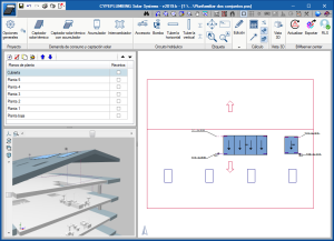
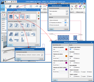
CYPEPLUMBING Solar Systems performs the design and analysis of the complete solar thermal energy contribution installation for hot water and heating, or part of it, in any type of building, in compliance with the corresponding standard and with personalised design configurations of other standards or personal technical limits.
In its first version, “CYPEPLUMBING Solar Systems” includes the prescriptions of CTE DB HE 4 (Spain) and the possibility to establish other conditions to comply with standards of other countries. In upcoming versions, other standards will be implemented, so users will not have to define their requirements and can simply select the code to be applied.
CYPELUMBING Solar Systems can be downloaded from the BIMserver.center platform and is integrated in the Open BIM workflow using the IFC standard.
The program designs the thermal installation using the F-Chart method and performs the hydraulic analysis (automatic design), using the “Darcy and Weisbach” formulas, and calculates the friction factor using the “Colebrook and White” equation.
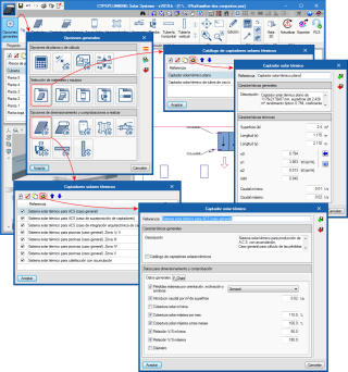
It contains predefined equipment catalogues to develop the installations, but also allows configurable catalogues to be introduced.
CYPEPLUMBING Solar Systems allows users to configure the design and checks that have to be carried out on any of the elements of the installation (solar thermal collectors, storage tanks, valves, circulation pumps, horizontal and vertical pipes).
Having completed the analysis, check and design processes, CYPEPLUMBING Solar Systems generates:
- The results, quantities and checks reports
These are available from the program itself and are also exported to the BIM model where they are available for the rest of the intervening agents who have the permits to consult the project documentation. - The quantities to be exported in the standard FIEBDC-3 format
That can be used by bill of quantity programs to elaborate the budget of the installation. - The drawings of the installation
That can be printed from the program and exported to different formats (DXF, DWG, JPG, EMF, BMP).
To be able to work with “CYPEPLUMBING Solar Systems” users must have the corresponding permit, which is the same as for the CYPECAD MEP module “Solar thermal energy”. The permit must be updated to the 2019 or later versions.
Even though CYPEPLUMBING Solar Systems shares the same permit as the CYPECAD MEP module “Solar thermal energy”, “CYPELUMBING Solar Systems” has important advantages, which include:
- Hot water and heating
CYPEPLUMBING Solar Systems carries out the design and analysis for the production of domestic hot water (DHW) and heating. The module of CYPECAD MEP only designs the solar thermal energy installation for the production of hot water. - Integration in the Open BIM workflow
Unlike the “Solar thermal energy” module of CYPECAD MEP, CYPELUMBING Solar Systems is integrated in the Open BIM workflow, a multidisciplinary and multi-user methodology, which allows projects to be developed in an open, coordinated and simultaneous manner amongst the designers or intervening agents.
More information on this new CYPE program will be available shortly.
Open BIM Suspended ceilings
Project example
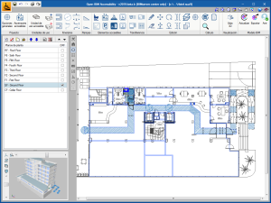
A project example has been included in the program.
CYPECAD
Secondary columns against seismic action
In the 2017.a version, a new option was implemented in the program where users could define the seismic-resistant category of beams, and in the 2017.c version, of beams. As of the 2019.b version, the seismic-resistant category of columns can be defined.
Secondary structural elements against seismic action are those that are not part of the seismic-resistant system of the building against this action.
As of the 2019.b version, CYPECAD allows users to assign and define three seismic-resistant categories for columns:
- Primary column
- Secondary column
- Wall edge reinforcement column
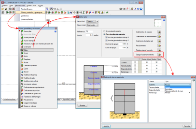
By default, all the columns of a project are considered as primary. It is users who decide which columns are to be considered as secondary or as wall edge reinforcement. For this purpose, the "Seismic Resistant Category" option has been implemented in the column introduction and edit dialogues. With this option, the desired seismic-resistance category can be assigned to each column span.
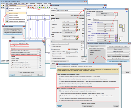
For the purposes of the seismic analysis, the stiffness of the secondary elements will be reduced by applying the factors defined in the "Inertia reduction factors" dialogue ("Project"> "General options" > "Inertia reduction factors”). This reduction will not be applied to the mass of the secondary elements.
In terms of capacity design and seismic design requirements, the design and verification options defined in the “Secondary columns against seismic action” dialogue will be applied to the "secondary columns" and the "wall edge reinforcement columns" ("Project" menu> "General data"> "By position" button> "Options for columns, shear walls, walls and corbels”> "Design/ Code checks" section> "Secondary columns against seismic action" option).
The indicated inertia reduction factors and the capacity design options depend on the selected seismic code. Users, however, can define other reduction factors and select the capacity design options to apply.
For all these options to be active, users must have activated the seismic analysis with a seismic code that is compatible with the selected concrete code.
View the forces on the floor plan
As of the 2019.b version, the forces acting in the floor plan are displayed in the frame editor for frames that are disconnected from the rigid diaphragm.
StruBIM Anchors ACI 318
Project examples
Three project examples have been included in the 2019.b version of StruBIM Anchors ACI 318:
- Steel section - footing
- Steel section - floor slab corner
- Steel beam - concrete wall
CYPELEC Networks, CYPELEC Core, CYPELEC NF and CYPELEC REBT
Connection between CYPELEC Networks and CYPELEC Core, CYPELEC NF and CYPELEC REBT
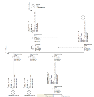
CYPELEC Core, CYPELEC NF and CYPELEC REBT design low voltage installations. In previous versions of CYPELEC Networks, users had to manually introduce the loads that correspond to the low voltage installations (calculated in the aforementioned programs), which are supplied by the medium or high voltage network, and were going to be analysed in CYPELEC Networks.
As of the 2019.b version, and thanks to the Open BIM connection of these programs, CYPELEC Core, CYPELEC NF and CYPELEC REBT can export the demanded or foreseen power (power and power factor) that is required by the installations they design to the BIM model.
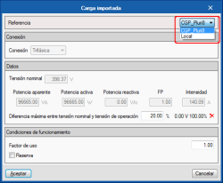
This way, when a project is begun in CYPELEC Networks, by connecting to the BIM model to which the demands of the installations that have been designed in CYPELEC Core, CYPELEC NF and CYPELEC REBT have been exported, CYPELEC Networks users will be able to import the IFCs that are generated by the programs and will decide which loads will be part of the high or medium voltage diagram.
To select these loads, CYPELEC Networks has a new tool represented by  , located in the “Terminal elements” section of the toolbar.
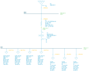
When this tool is selected, the program allows users to select the desired load among those imported from the BIM model to include it in the diagram and continue with the electrical installation. Each time this tool is selected, one of the imported loads can be selected.
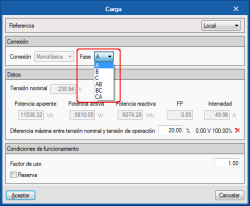
If the imported load is single-phase, it will be possible to select to which phase is connected.
In the project, imported loads can be combinedand user can introduce their own loads created directly in CYPELEC Networks.
CYPELEC Core, CYPELEC NF and CYPELEC REBT
Electric supply using two generators in parallel
As of the 2019.b version, CYPELEC Core, CYPELEC NF and CYPELEC REBT allow for the electrical supply to be provided by two generators connected in parallel, one of which configured as the main supply and the other a complementary supply, to provide for all the installation.
CYPELEC Core and CYPELEC REBT
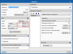
Increase in the number of circuits or number of conductors per pole
The group correction factors of all the installation methods corresponding to the UNE 211435 and IEC 60364-5-52 codes have been checked, to increase the number of conductors per pole (number of circuits) from 9 to 20.
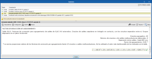
It is possible that some tables, for certain installation methods, do not provide a group correction factor for a high number of conductors, in which case the program uses the most unfavourable factor amongst those indicated in the table, and indicates it with a warning message when checking the maximum admissible current or ampacity.
This increase allows users to use, for example, cables of over 2500 A for transformer outputs.
CYPELEC Core
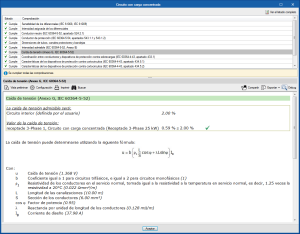
Automatic voltage drop design
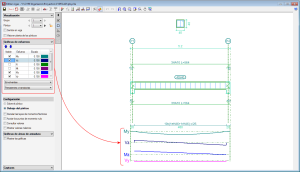
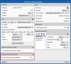
As of previous versions, CYPELEC Core allowed users to activate the maximum allowable voltage drop check for a specific line using the option indicated in the image.
As of the 2019.b version, this limitation becomes a design criterion, in other words, the program will increase the section to comply with the imposed limit.
Translation into Italian and Portuguese
CYPELEC Core has been translated into Italian and Portuguese. Therefore, it can be downloaded from the BIMserver.center and installed in these languages, as well as in Spanish or Catalan, for which it was already available as of its first version.
CYPETHERM LOADS
Thermal envelope of the building in GLTF standard format
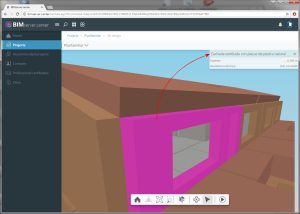
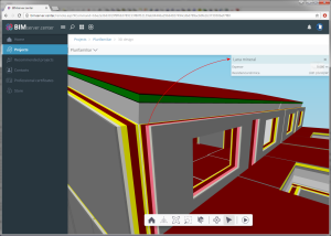
As of the 2019.b version, CYPETHERM LOADS exports two independent GLTF files (attached to the IFC), containing the thermal information of the enclosures of the building, to the BIM project located on the BIMserver.center platform. Each GLTF file allows users to view the data differently in any viewer that interprets the GLTF standard format (AUTODESK Viewer, glTF Viewer, BIMserver.center web viewer...):
- Thermal model, by element
The complete construction solutions used in the building are shown together with their properties (reference, thickness and thermal resistance). - Thermal model, by layers
The individual layers making up each construction solution are shown together with their properties reference, thickness and thermal resistance).
CYPETHERM programs with EnergyPlus™ analysis engine (CYPETHERM EPlus and CYPETHERM RECS Plus)
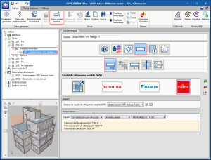
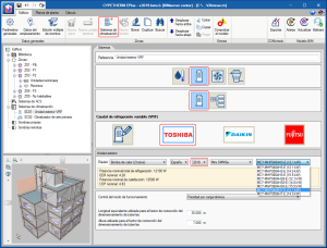
FUJITSU Airstage variable refrigerant flow (VRF) systems
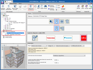
The FUJITSU Airstage equipment catalogue has been integrated into CYPETHERM programs with the EnergyPlus engine (CYPETHERM EPlus and CYPETHERM RECS Plus). This way, the number of manufacturers available to users when defining a variable refrigerant flow (VRF) type system is increased.
The FUJITSU logo has been added to the VRF button located in the "Direct Expansion" Air Conditioning Systems. By selecting it, users can choose between the different series and models of FUJITSU Airstage outdoor units, which are completely defined within the program. Similarly, FUJITSU Airstage indoor units can be added via the "VRF" button (New terminal unit > Direct expansion terminal unit > VRF button).
It is not possible to combine indoor and outdoor VRF systems belonging to different manufacturers, neither can manufacturer models with generic unit.
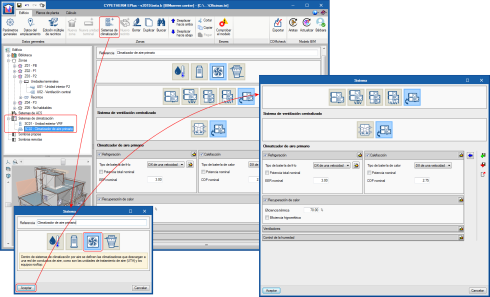
Primary air conditioner
A new type of air conditioning equipment has been added: the Primary air conditioner.
The primary air conditioner can be selected in "Air conditioning systems > Air-air conditioning system > Central ventilation system". It is an air conditioner that introduces treated outdoor air into the building. Options for outdoor air conditioning include cooling, heating, humidity control and heat recovery.
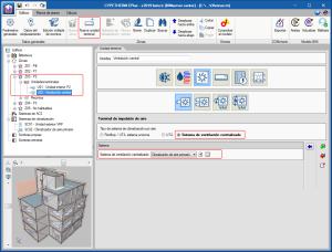
The primary air conditioner is connected to the zones defined in the building via the air conditioning terminal unit: "Air discharge terminal" > "Central ventilation system". The primary air conditioner will perform the function of ventilation in areas to which it is connected, therefore these zones must be defined with "Via the air conditioning system" type of ventilation.
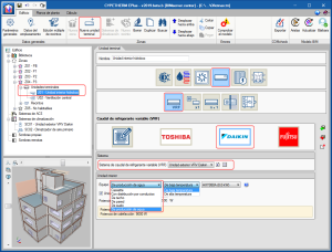
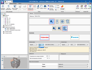
Daikin water production indoor VRV units
Daikin "Water production" type indoor VRV units, offered by the manufacturer, have been added (New terminal unit > Direct expansion terminal unit > Variable refrigerant flow > Daikin > "Water production" indoor water selection).
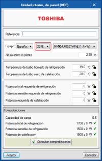
Update of the 2018 Toshiba equipment catalogue
As occurs with CYPETHERM HVAC, some equipment of the Toshiba catalogue has been updated in the 2019.b version of CYPETHERM EPlus and CYPETHERM RECS Plus. This equipment is shown as belonging to the 2018 category in the equipment selection panel.
CYPETHERM HVAC
Update of the 2018 Toshiba equipment catalogue
As occurs with CYPETHERM EPlus and CYPETHERM RECS Plus, some equipment of the Toshiba catalogue has been updated in the 2019.b version ofCYPETHERM HVAC. This equipment is shown as belonging to the 2018 category in the equipment selection panel.
Arquimedes, and Arquimede and Job control
Export information to the BIM model
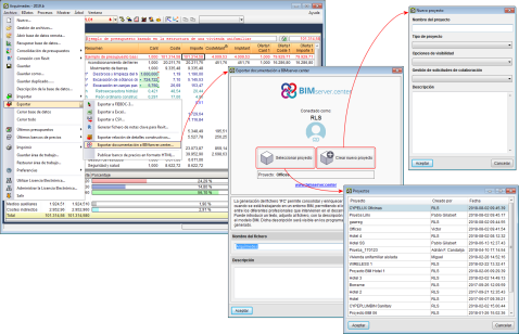
As of the 2019.b version, “Arquimedes” and “Arquimedes and job control” can be connected to a BIM model that is located on the BIMserver.center platform to export the following project information, if it is included in the program:
- Quality control program
- Construction and demolition waste analysis
- Life cycle analysis
- Project specifications
- Quantities
- Bill of quantities
This information can be imported by the Open BIM Memorias CTE program, which will use it to complete the corresponding section of the project documentation.
To do so, a new option has been included in "Arquimedes", and "Arquimedes and Job control": "Export documents to BIMserver.center" (File > Export), which opens a panel with the same name. In this panel, the user can choose the BIM project to which the information is to be exported (from amongst the projects in which the user participates) or to create a new BIM project.
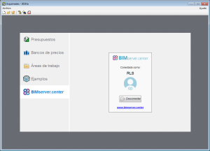
In the start screen of Arquimedes (implemented in version 2019.a), there is also a new section that allows users to connect or disconnect from the BIMserver.center platform or access it using the Web browser used by users.
Return to the 2019 version download area
Tel. USA (+1) 202 569 8902 // UK (+44) 20 3608 1448 // Spain (+34) 965 922 550 - Fax (+34) 965 124 950
