
- New modules and programs
- BIMserver.center
- Open BIM complement for Revit
- CYPECAD
- CYPECAD MEP
- CYPELEC REBT, CYPELEC NF and CYPELEC Core
- CYPELEC Multiline
- CYPETEL Wireless
- CYPEPLUMBING Sanitary Systems
- CYPEPLUMBING Water Systems
- CYPELUX, CYPELUX CTE, CYPELUX RECS, CYPELUX LEED and CYPELUX HQE
- CYPEFIRE Design
- CYPETHERM programs with the EnergyPlus analysis motor (CYPETHERM EPLUS, CYPETHERM HE PLUS and CYPETHERM RECS Plus)
- CYPETHERM HVAC
- Arquimedes
- Return to the 2018 version download area
New modules and programs
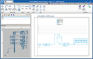
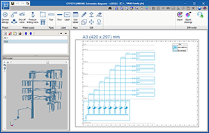
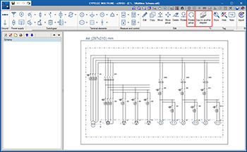
CYPEPLUMBING Schematic diagrams
CYPEPLUMBING Schematic diagrams is a free tool that automatically creates water supply installation diagrams.
This application is integrated in the Open BIM workflow using the IFC standard. It is only available by downloading it from the BIMserver.center platform.
For installations with more than consumer, the program provides two diagrams, one from the supply connection to the water meter assembly and another from the assembly to the shut-off valve of the consumer. For installations with a single consumption point, the program generates a diagram from the supply connection to the shut-off valve of the consumer.
CYPEPLUMBING Schematic diagrams automatically generates the water supply installation diagram if the BIM model contains the required information, which can be generated by CYPEPLUMBING Water Systems. The diagram that is generated can be modified using the tools that are available in the top part of the program screen.
If the BIM model does not contain the aforementioned information, it can be designed manually using the same tools with which it can be modified. Therefore, “CYPEPLUMBING Schematic diagrams” can work autonomously, although a BIM project must always be created on the BIMserver.center platform.
BIMserver.center
Download CYPE programs from the BIMserver.center platform
The following CYPE programs can be downloaded from the BIMserver.center platform:
- iTCalc
Analysis and design of telecommunication installations using systems of the Televés catalogue.
Only available on the BIMserver.center platform (installation in Portuguese) as of the 2018.l version - CYPEDOC CTE SUA 8
Tool designed to evaluate the need to install a protection system against risks due to lightning in accordance with DB SUA 8 of the “Código Técnico de la Edificación”.
Only available on the BIMserver.center platform (installation in Spanish and Catalan) as of the 2018.l version - CYPEPLUMBING Schematic diagrams
Free program designed to create the diagram of a common water supply installation.
Only available on the BIMserver.center platform as of the 2018.l version. - CYPETEL ICT
Analysis and design of the common telecommunications infrastructure to access the telecommunication services inside buildings in accordance with “Real Decreto 346/2011”.
Available on the BIMserver.center platform (installation in Spanish and Catalan) as of the 2018.l version; and also as of previous versions in the CYPE program general menu in Spanish or Catalan, which can be downloaded from the Downloads webpage. - CYPETEL ITED
Elaboration of telecommunication networks for multi-family and single-family homes in accordance with the “Manual ITED 3.ª edição”.
Available on the BIMserver.center platform (installation in Portuguese) as of the 2018.l version; and also as of previous versions in the CYPE program general menu in Portuguese, which can be downloaded from the Downloads webpage. - CYPESOUND CTE
Acoustic design and verification of airborne noise and impact noise insulation, and the reverberation level using the general design option described in CTE DB HR. Check of the immission grade in accordance with law 37/2003, of 17th November, of the noise.
Available on the BIMserver.center platform (installation in Spanish and Catalan) as of the 2018.l version; and also as of previous versions in the CYPE program general menu in Spanish and Catalan, which can be downloaded from the Downloads webpage. - CYPESOUND RRAE
Acoustic design and verification of airborne noise and impact noise insulation; of the sound absorption area; of the reverberation time; and the sound immission level caused by the equipment of the building in accordance with the “Regulamento dos Requisitos Acústicos dos Edificios (DL nº96/2008)” and with the EN 12354 (ISO 15712) design codes.
Available on the BIMserver.center platform (installation in Portuguese) as of the 2018.l version; and also as of previous versions in the CYPE program general menu in Portuguese, which can be downloaded from the Downloads webpage.
Export data to BIMserver.center

3D viewer
Since the 3D view in “GLTF” format was implemented in the 2018.i version of programs integrated in the Open BIM workflow, 3D models can be viewed in the viewer that is integrated on the BIMserver.center Web platform and in its application (App) for mobile devices.
As of the 2018.l version, the amount of information the following CYPE programs export to the 3D viewer of BIMserver.center has been increased:
- CYPELUX, CYPELUX CTE, CYPELUX RECS, CYPELUX LEED and CYPELUX HQE
Exports contour map diagrams. More information on the Contour map diagrams in BIMserver.center section of the new features of CYPELUX of this webpage.
Open BIM complement for Revit
Compatibility of “Revit® 2019” with CYPE programs
As of the 2018.l version of CYPE, the complements that have been developed for Revit (“Open BIM complement” and “Bill of quantities of Revit models”) are compatible with the 2019 version of Revit.
CYPECAD
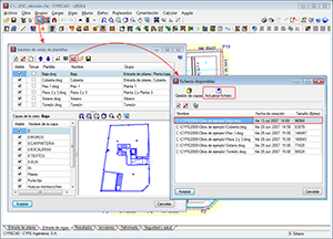
Template updates using the F2 key
As of the 2018.l version, all the drawing templates of the project with changes can be updated using the “F2” key.
Templates are also updated when they are viewed for the first time since the project has been opened or they can be updated manually (one by one) from the “Available files” dialogue box (as shown in the image).
CYPECAD MEP
Update to the 8.9 version of the EnergyPlus™ analysis engine
The 2018.l version of CYPECAD MEP uses the 8.9 version of the EnergyPlus analysis engine, published on the 30th March 2018.
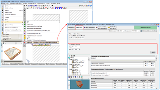
Time period simulation with EnergyPlus™ from CYPECAD MEP
The 2018.l version of CYPECAD MEP and CYPETHERM programs with the EnergyPlus analysis engine (CYPETHERM EPlus, CYPETHERM HE Plus and CYPETHERM RECS Plus) allows users to define the simulation of the time period of EnergyPlus. In previous versions, users could only simulate the whole year or two design days.
When the data of the project in CYPECAD MEP is exported to Energy Plus (from the “Air conditioning” tab), a process begins that ends with the program displaying the “Viewer for data exported to Energy Plus”. It is here that the EnergyPlus analysis motor is used and where, as of this, the 2018.l version, users can select the desired time period.
More information on how to select the simulation period in CYPETHERM programs can be found in the “Time period simulations with EnergyPlusTM from CYPETHERM programs” section.
CYPELEC REBT, CYPELEC NF and CYPELEC Core
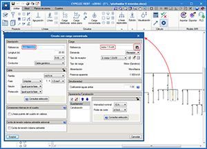
Copy the reference of the line to the load
In some panels, as is the panels of circuits with concentrated loads, users can indicate a reference for the circuit and a different reference for the load. When the same reference is to be used for the circuit and the load, a button has been added (next to the reference of the load) to be able to quickly copy the reference.
CYPELEC Multiline
New editing tools
Two new tools have been added to the “Edit” menu of the CYPELEC Multiline toolbar: “Rotate group” and “Copy to another diagram”.
Rotate group
Allows users to capture several elements and rotate them at once.
Copy to another diagram
Allows users to select one or several elements from a diagram and copy them to another. This tool works in a similar way as the tool for copying elements between floors in other CYPE programs.
CYPETEL Wireless
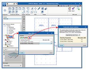
Import assistant for construction element attenuation data
As of the 2018.l version, CYPETEL Wireless has an assistant, which has been created to help define attenuation values of construction elements. The assistant allows users to import attenuation data of different predefined construction elements.
Reading of telecommunication inlets of the BIM model
Thanks to the inclusion of iTCalc in the Open BIM workflow (software that exports the position of telecommunication inlets to the BIM project), CYPETEL Wireless positions the copper pair cable inlets on the floor plans to assist users when configuring their wireless network (as well as displaying them in the 3D view of the BIM model, as occurs with all the programs included in the Open BIM workflow).
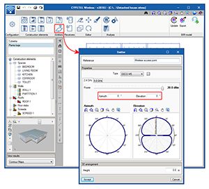
Orientation of emitter antennas
The 2018.l version of CYPETEL Wireless includes the possibility to vary the azimuth and elevation angles of emitter antennas. This allows users to define the direction of the radiation diagram depending on the requirements of the installation.
CYPEPLUMBING Sanitary Systems
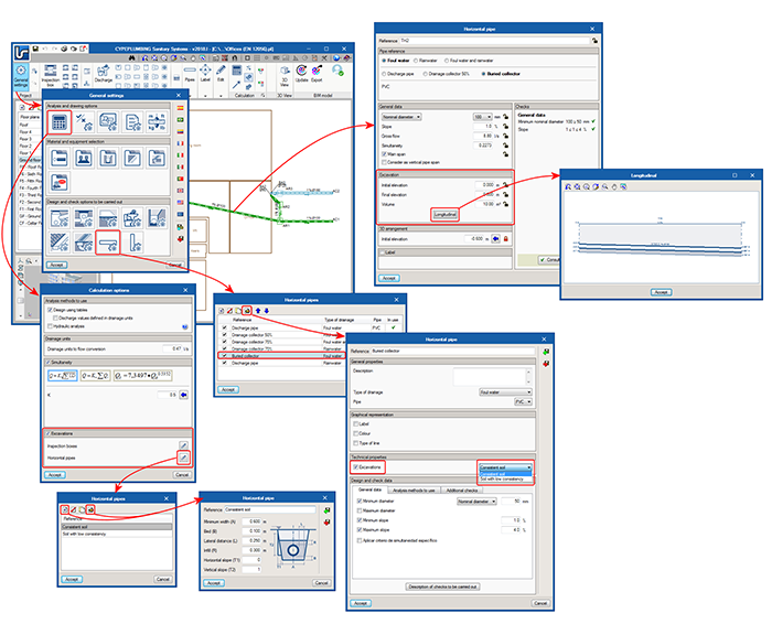
Excavation volume
The 2018.l version of CYPEPLUMBING Sanitary Systems can calculate the excavation volumes of inspection chambers and horizontal pipes. For the program to be able to carry out this calculation, users must define:
- Geometric properties of the transverse excavation profiles
Several transverse profiles of inspection chambers and horizontal pipes can be introduced and included in a library to use them in different projects.
They are defined in “General settings > Analysis and drawing options > Calculation options > Excavations”.
There are no predefined profiles by default; users must create them. In an upcoming version, predefined profiles will exist with the properties that are specified in the selected code. Users will be able to edit them and add new profiles. - Selection of types of inspection chamber and horizontal pipes with excavations
Users must select the transverse excavation profile to be used depending on the type of inspection chambers and horizontal pipes for which the soil must be excavated. - Introduction of inspection chambers and horizontal pipes
When users introduce the types of inspection chambers and horizontal pipes indicated in the previous step, the initial and final elevations of the ground must be introduced, and the program will automatically assign the excavated volume based on these elevations, the data of the transverse section of the excavation and the inlet and outlet elevations of the inspection chambers. The excavated volume that is calculated can be modified manually. Users can block the initial and final elevations of the ground, and the excavation volumes, so they do not change in future result updates.
The program displays the longitudinal profile of the horizontal pipes on-screen, which can be printed or exported to different drawing format files.
The quantities report of the network includes the excavation volumes of the inspection chambers and horizontal pipes for which the previously mentioned data has been defined.
New checks
Maximum distance between cleanouts and cleanouts at pipe spans with a change of direction
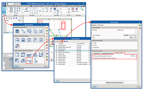
As of the 2018.l version, CYPEPLUMBING Sanitary Systems allows users to define the maximum distance that must exist between horizontal pipe cleanouts and cleanouts at pipe spans with a change of direction.
To do so, the “Horizontal pipe” dialogue box (General settings > Design and check options to be carried out > Horizontal pipes > select or define a type of horizontal pipe) has been reorganised; the “Design and check data” section now consists of three tabs “General data”, “Analysis methods to use” and “Additional checks”. The latter tab contains the two cleanout checks that have been mentioned (Maximum distance between cleanouts and Cleanouts in the changes in direction of the pipe).
These checks can be selected for each type of horizontal pipe that is defined in the project.
The program emits warning when the checks fail for the horizontal pipes for which they have been activated.
These checks are currently deactivated by default and users must activate them if they wish. In an upcoming version, they will appear activated if they are contemplated in the selected code. Users will be able to freely activate, deactivate or modify the maximum distance.
Maximum distance between water seals and ventilated sections
As of the 2018.l version, CYPEPLUMBING Sanitary Systems allows users to define the maximum distance that must be present between the discharge water seals and the closest ventilated section.
This check is located in the “Design and check data” section of the “Discharge” dialogue box (General settings > Design and check options to be carried out > Discharges > selection or definition of a type of discharge) and can be defined individually and with different values for each type of discharge. Users establish the maximum distance for each slope interval they wish to define in a table.
The program will emit warnings when this check fails for the types of discharges for which it has been defined.
This check is currently deactivated by default. Users must activate it, if it is to be contemplated. In an upcoming version, the check will appear activated with the values corresponding to the selected code. Users can modify these values or deactivate the check.
New design options
Specific simultaneity criteria
As of the 2018.l version of CYPEPLUMBING Sanitary Systems, users can define specific simultaneity criteria for a type of horizontal or vertical pipe, different to that which has been defined for all the installation in “General settings > Analysis and drawing options > Calculation options > Simultaneity”.
The specific simultaneity criteria are defined in: General settings >Design and check options to be carried out > “Horizontal pipes” or “Vertical pipes” > Select or define a type of pipe > “Design and check data” section > activate “Apply specific simultaneity criteria”.
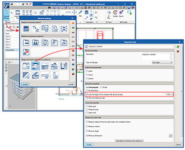
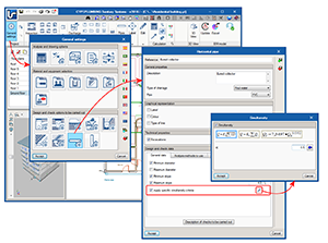
Limit chamber inlet heights
The possibility to “Limit the height of the chamber inlet above its base” has also been implemented. This option can be activated and the limit can be defined individually for each type of “Inspection box” in the “Dimension properties” section of the “Inspection box” dialogue box (General settings > design and check options to be carried out > Inspection boxes > Selection or definition of a type of inspection box).
This option is deactivated by default and it is users that must activate it and indicate the limit value. In an upcoming version, it will appear activated in accordance with the values established in the selected code and users will be able to deactivate or edit it to modify the limit.
CYPEPLUMBING Water Systems
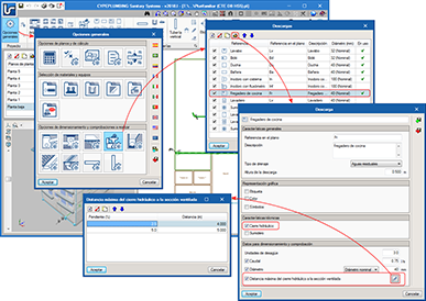
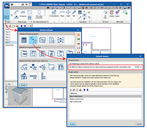
Check the maximum distance between the hot water production equipment and the consumption point
As of the 2018.l version of CYPEPLUMBING Water Systems, users can define the maximum distance between the hot water production equipment and the consumption point. If the check is activated and the distance is defined, the program will display a warning at the consumption points that exceed it.
This check is activated in “General options > Analysis and drawing options > General checks”
The check is deactivated by default. In an upcoming version, it will be activated with the value that is established in the selected code and users will be able to deactivate or edit it to modify the limit.
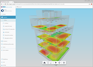
CYPELUX, CYPELUX CTE, CYPELUX RECS, CYPELUX LEED and CYPELUX HQE
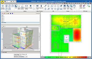
Contour map diagrams in the 3D view of the program
As of the 2018.l version, CYPELUX can represent the contour maps of the results in the 3D view of the BIM model. This option can be activated using the “View results” panel, once the project has been analysed.
Contour map diagrams in BIMserver.center
When the project information is exported to BIMserver.centre, the IFC file that is generated has several “.gltf” file referenced to it, which contain the contour maps of each result represented in the 3D view of the program (maintained horizontal illuminance, unified glare rating, daylight coefficient...). This allows users to view the contour maps in the 3D viewer of BIMserver.center, in a similar way as is done in other Open BIM applications such as CYPETEL Wireless.
The “.gltf” files that are generated by CYPELUX programs are independent of each other and of the file that is generated for lights since the previous version (2018.k), so each one can be viewed independently.
CYPEFIRE Design
IGH (Immeubles de grande hauteur) project types for the Moroccan code
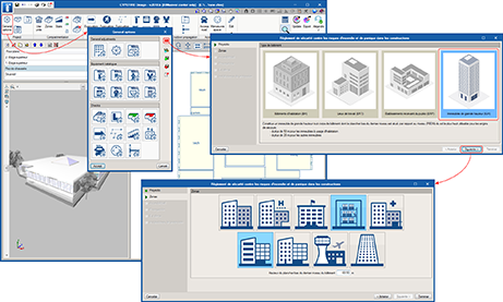
The 2018.l version of CYPEFIRE Design includes the following types of IGH buildings (Immeubles de grande hauteur) for the Moroccan code: “Règlement de sécurité contre les risques d’incendie et de panique dans les constructions”, which correspond to buildings which are over 28m in height or residential buildings with a height of over 50m:
- GHA
- GHO
- GHR
- GHS
- GHU
- GHW
- GHZ
- GHTC
- ITGH
New checks
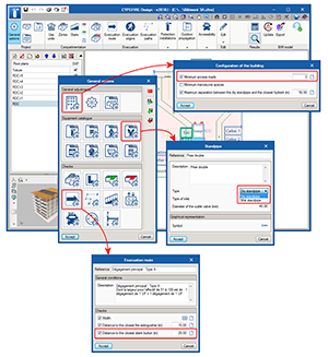
Minimum access roads
The 2018.l version allows users to check the minimum number of access roads that are required depending on the type of code and project to solve.
Distance to alarm buttons
If the alarm buttons are introduced on access roads (as occurred with fire extinguishers as of previous versions), the program will check that any evacuation origin is not located at a distance greater than that introduced by users in the “Evacuation routes” dialogue box.
Wet standpipes
It is now possible to introduce “Wet standpipes”. To do so, the “Dry standpipe” option in the “Equipment catalogue” section of the “General options” dialogue box, has been changed to “Standpipe” and in its description, users can choose the type of standpipe “Dry standpipe” or “Wet standpipe” that is to be defined.
CYPETHERM programs with the EnergyPlus analysis motor (CYPETHERM EPLUS, CYPETHERM HE PLUS and CYPETHERM RECS Plus)
Update to the 8.9 version of the EnergyPlus™ analysis engine
The 2018.l version of CYPETHERM with the EnergyPlus analysis engine uses the new 8.9 version of the engine that was published on the 30th March 2018.
Time period simulations with EnergyPlus™ from CYPETHERM programs
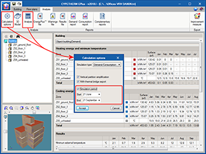
The 2018.l version of CYPECAD MEP and CYPETHERM programs with the EnergyPlus™ analysis engine (CYPETHERM EPlus, CYPETHERM HE Plus and CYPETHERM RECS Plus) allows users to define the simulation of the time period of EnergyPlus. In previous versions, users could only simulate the whole year or two design days.
In the “Analysis” tab of CYPETHERM EPlus or in the “Code verification” tab of CYPETHERM HE Plus and CYPETHERM RECS Plus, the “Calculation options” panel appears when the “Analyse” or “Calculation options” buttons are pressed. The option, “Only simulate the design day” that used to appear in previous versions has been substituted in the 2018.l version by “Simulation period”, where users can define the initial and final day and month of the simulation.
More information on how to select the simulation period in CYPECAD MEP can be found in the “Time period simulation with EnergyPlus™ from CYPECAD MEP” section.
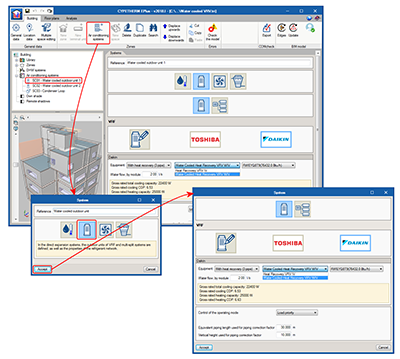
Daikin water-cooled variable refrigerant volume (VRV) outdoor units
New equipment has been added to the Daikin VRV equipment catalogue in CYPETHERM programs with the EnergyPlus analysis engine (CYPETHERM HE Plus, CYPETHERM RECS Plus and CYPETHERM EPlus). As of the 2018.l version, the “Heat pump” and “Heat recovery” versions of Daikin water-cooled VRV outdoor units (series RWEYQ8T9), can be simulated.
Within the Direct Expansion air conditioning systems, in the VRF button, then by clicking on the Daikin logo, users can choose amongst the different series and models of Daikin outdoor VRV units. If a Heat Pump system is selected (2-pipe), the new Water Cooled Heat Pump VRV WIV series appears, and similarly, if a Heat recovery system is selected (3-pipe), the new Water Cooled Heat Recovery VRV WIV series appears.
To simulate a water-cooled VRV system, a water condensation system for heat pumps must be added to the project.
CYPETHERM HVAC
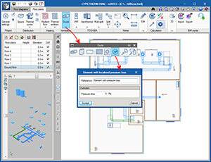
Element with localised pressure loss for air ducts
As of the 2018.l version, users can introduce an element with a localised pressure loss in the duct network to simulate the pressure loss that is generated by filters, dampers, etc.
This element is available in the “Ducts” section of the top toolbar, displayed using the “ΔP” icon.
Arquimedes
Bill of quantities of Revit models
Compatibility of “Revit® 2019” with CYPE programs
The “plugin” for Revit of the 2018.l version of CYPE, “Open BIM complement for Revit” and “Bill of quantities of Revit models” are compatible with the 2019 version of Revit.
Return to the 2018 version download area
Tel. USA (+1) 202 569 8902 // UK (+44) 20 3608 1448 // Spain (+34) 965 922 550 - Fax (+34) 965 124 950