
BIMserver.center
Program downloads on the BIMserver.center platform
The following CYPE programs are available to be downloaded from the BIMserver.center platform:
- CYPELUX CTE
- CYPELUX EN
- CYPELUX HQE
- CYPELUX LEED
- CYPELUX RECS
- CYPETHERM EPlus
- CYPETHERM RT2012
- CYPETHERM COMETH
- CYPETHERM REH
- CYPETHERM RTExistant
- CYPETHERM RECS Plus
- CYPETHERM C.E.
- CYPETHERM LOADS
- CYPETHERM HVAC
- CYPELEC REBT
- CYPELEC NF
- CYPELEC CT
These programs are also available on the main CYPE program menu, which is installed with the file that can be downloaded from the Download Area of the CYPE website.
CYPECAD
Pressures on walls
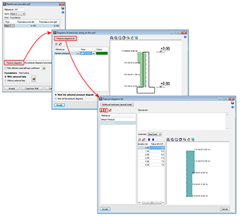
As of the 2018.e version of CYPECAD, pressures acting on walls can be defined. In previous versions, only soil pressures acting on walls could be introduced. With this improvement, as well as soil pressures, users can define a generic pressure diagram associated with any loadcase.
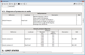
The Project data report includes the soil and generic pressures that have been defined in the project as well as the walls on which they act.
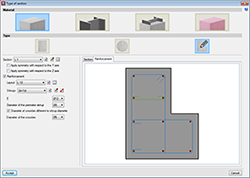
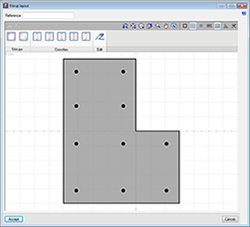
Stirrups in concrete columns with generic sections
The option to define stirrups in generic section columns has been implemented. The stirrups that are defined are measured and detailed in reports and drawings. The program does not carry out a shear check on these type of columns.
Different stirrup layouts can be defined for each longitudinal reinforcement arrangement that has been defined for a section.
When a stirrup arrangement is added or edited, users access the stirrup layout editor which contains different tools to define the stirrups and crossties that join the longitudinal reinforcement bars.
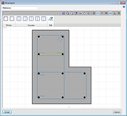
Users can place closed stirrups, open stirrups and different types of crossties. Crossties can have a different diameter to that of the stirrups.
After selecting the type of stirrup or crosstie, users have to select the longitudinal bars to be joined and finish off by clicking on the right mouse button.
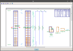
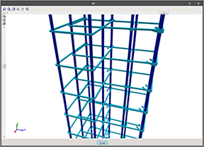
In “Results”, the spacing of the stirrups can be defined in the columns table, as well as the stirrup densification zones. Users can also view the details and consult the 3D view of the reinforcement.
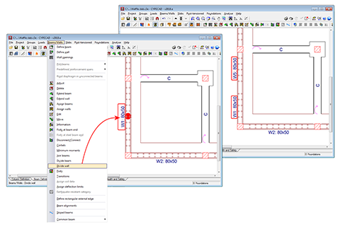
Divide wall
A tool has been implemented to divide walls. When a wall is divided, each part of the wall becomes a new wall with its own reference and properties.
Trapezoidal loads due to construction elements
Walls and partitions that end on a sloped slab (regardless of whether they have been introduced by users or imported from a BIM model) will generate a trapezoidal linear load.
CYPELEC Networks
Loadcase analysis
The definitions of status loadcases were included in the 2018.c version of CYPELEC Networks.
Now, in the 2018.e version, a powerful tool has been introduced to analyse all the loadcases that have been defined, which allows users to view the results of all the loadcases quickly and clearly. This tool allows users to obtain a global view of the results provided by the load flow analysis for all loadcases and aids them to adopt solutions to comply with the corresponding loadcases.
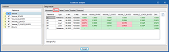
This tool is selected by pressing the “Loadcase analysis” button  located in the “Load flow” section of the toolbar, which opens a panel containing the loadcases that have been defined and their corresponding analysis results, all of which is organised in several tabs:
- Information tab
Shown in this tab are the design properties of the loadcases selected on the left, such as the number of buses, branches, generators, supplies and loads each loadcase consists of. The initial reference bus for the analysis of the load flow calculation is also specified as well as the resultant generation power.
- Buses tab
The resultant voltage values in PU in each bus for each loadcase are transferred here and are compared with the allowable accumulated voltage drop values that have been defined in General settings.
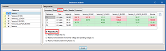
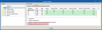
- Cables tab
The “Cables” tab is sub-divided into 4 sections:- Ampacity
Shows the resultant design current that flows through each cable or transmission line, and is compared with its ampacity.
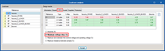
- Maximum voltage drop
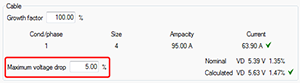
Shows the resultant voltage drop due to the impedance and admittance of the cable or transmission line, and is compared with the maximum voltage drop that has been introduced in the Edit panel.
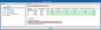
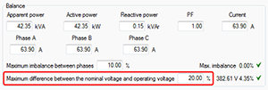
- Maximum error between the nominal voltage and operating voltage (%)
Shows the percentage resultant error between the nominal voltage and operating voltage, and it is compared with the value that is introduced in the Edit panel of the cable or transmission line.
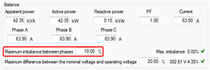
- Maximum imbalance between phases (%)
Shows the percentage resultant imbalance between the most loaded phase and the least loaded, and is compared with the maximum imbalance value between phases that has been introduced in the Edit panel of the cable or transmission line.
- Ampacity
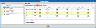
- Loads tab
Here, represented for each loadcase, are the values of the active and reactive power of the loads, which are affected by the use and simultaneity criteria specified for each loadcase.
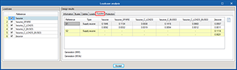
- Supplies tab
The resultant values of the active and reactive power generated by each supply are displayed for each loadcase, in accordance with the load flow calculation.
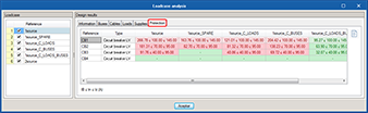
- Protection tab
Also for each loadcase, represented in this tab is the check that relates the nominal or protection regulating current, with the design current of the line and ampacity of the cable it protects.
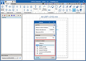
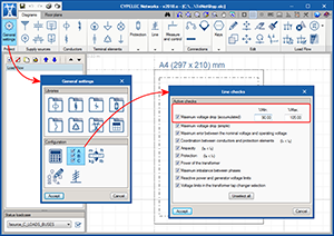
Selection of loadcases to analyse
In the “Settings” option of the “Load flow” section of the toolbar, users can now select the loadcases which are to be analysed. This selection affects the analysis process of the loadcase in such a way that only the properties and results of the loadcases selected in this section will be referred to.
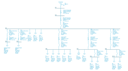
New project example
The project example “General industry” has been added corresponding to the electrical installation of an industry.
CYPEFIRE Design

Generation of the fire safety installations project
As of the 2018.e version, CYPEFIRE Design generates the “Fire safety installation project”. In this document, the program includes detailed check reports which display the titles, descriptions of each section and references of the articles of the design code (Compartmentation, External propagation, Evacuation routes, Fire safety installations, Firefighter accessibility). The “Checks” report (available as of previous versions), only displays a summary in tables of the checks carried out in each section.
New types of projects
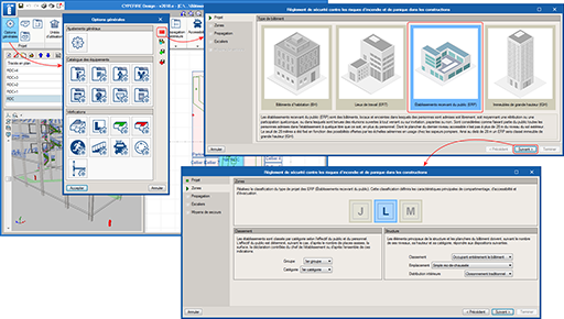
The following types of projects, belonging to the Moroccan code: “Règlement de sécurité contre les risques d’incendie et de panique dans les constructions”, have been added:
- Établissements recevant du public: Salles d’audition, de conférences, de réunions, de spectacles ou à usages multiples (Type L).
- Établissements recevant du public: Magasins de vente, centres commerciaux (Type M).
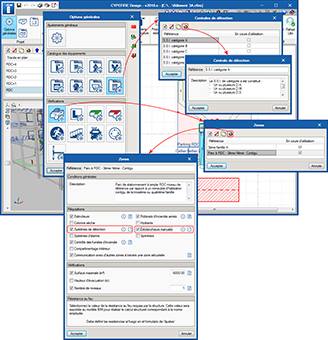
Risk zones
Checks on “Risk zones” have been added in the “Checks” section of the “General settings” panel.
In this version, risk zones are defined based on their description and the fire resistance of the structure. In upcoming versions, the definition of risk zones will be expanded so to reach a similar level as for zones, which will allow users to indicate fire safety installations (fire extinguishers, sprinkler systems, detectors, etc.) and communication with other zones via safe zones.
Firefighter access
A new section “Accessibility” has been implemented in the top toolbar regarding the accessibility options for firefighters. This section contains two tools:
- Access road
The “Access road” for firefighters is a simple graphical tool, designed to comply with the requirements prescribed for these routes. By introducing the basic input data (free width, width of the road and length of the road), it is possible to quickly check if the surrounding elements of the project are valid. - Manoeuvre space
The “Manoeuvre space” is also a graphical tool with which users can define the manoeuvre space the fire truck has to reach the access points of the building. The following checks are carried out:- Minimum free width
- Length
Protection installations
The 2018.e version of CYPEFIRE Design includes a new fire protection element: “Fire alarm control panels”. Also in this version, the requirements of “Alarm buttons” are defined separately.
Detection centres
The detection centres control all the signals the detectors receive and commands the alarm system.
Their definition is very simple. Users must only indicate their reference and a description of the elements that make up the detection centre.
Alarm buttons
Alarm buttons (or manual buttons) already existed in CYPEFIRE Design, but the limits as of which they had to be placed, were defined together with automatic fire detectors (Detection systems). As of the 2018.e version, the limits for these alarm buttons are defined separately and no longer together with the automatic fire detectors.
Open BIM workflow
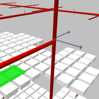
Export the fire resistance of the structure to the BIM model
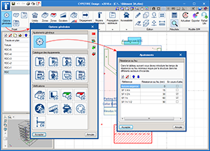
As of the 2018.e version, CYPEFIRE Design exports the fire resistance information of the structure to the BIM model (requirement reference and minimum required fire resistance period of each space). This data can be read by structure programs that can import BIM models such as CYPECAD.
Based on the information of each space, CYPEFIRE Design generates a fire resistance zone that can be exported to the BIM model. When CYPECAD imports the information of the BIM model, it automatically activates the “Check fire resistance” option. Spaces which do not contain fire resistance information generate a “Without fire resistance check” zone.
In CYPEFIRE Design, users can edit the fire resistance period of the structure in the “Adjustments” panel (General options > General adjustments). Within this panel, a minimum resistance period can be associated to each fire resistance denomination of the code. Then, a minimum fire resistance period can be associated to each type of zone or risk zone.
Export sectors which require sprinklers to be installed to the BIM model
As of the 2018.e version, CYPEFIRE Sprinklers can read the information that has been exported to the IFC file from CYPEFIRE Design, such as the need to install sprinklers in a zone or sector that has been created.
As of the 2018.e version, CYPEFIRE Design can export to the BIM model, the requirement to include a sprinkler system installation in zones or sectors that have been created. CYPEFIRE Sprinklers can read this information in the IFC file created by CYPEFIRE Design in the BIM model.
Import glazed openings from the BIM model
Windows defined in the architectonic model of the BIM project can be imported by CYPEFIRE Design. This not only helps users to understand the architectonic model on the program interface but also helps to adequately introduce safety installations and, in upcoming versions, the automatic resolution of checks to avoid external propagation.
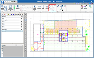
CYPEFIRE Sprinklers
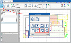
Improved interface
The 2018.e version of CYPEFIRE Sprinklers includes improvements in the organisation of its interface which also contains new tools to introduce seismic supports for the sprinkler systems.
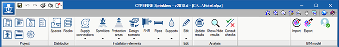
Interface of earlier versions than the 2018.e version
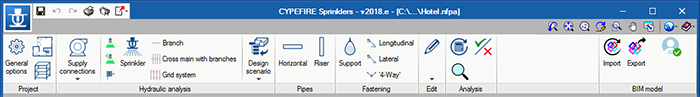
Interface of the 2018.e version
The main differences are:
- Project
Now, all the libraries and configuration menus are located in General options. The “Distribution” menu also disappears and is relocated in the latter. - Installation elements
This menu disappears and is divided into several menus. Now we can find:- Hydraulic analysis elements
Located here are tanks, sprinklers, fire hoses and the tool to create design scenarios. - Pipes
Includes risers and horizontal pipes. - Fastening
Includes supports and seismic supports for pipes.
- Hydraulic analysis elements
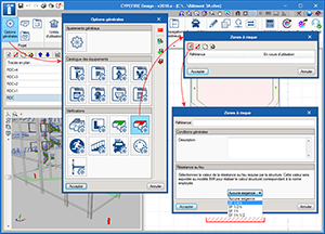
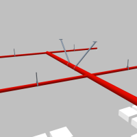
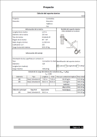
Seismic supports for sprinkler systems
To avoid the sprinkler systems from being damaged during an earthquake, the NFPA 13 code prescribes the use of seismic supports that resist the horizontal loads inflicted on the system. The 2018.e version of CYPEFIRE Sprinklers includes the introduction and check of seismic supports for the sprinkler system in accordance with the prescriptions of this code.
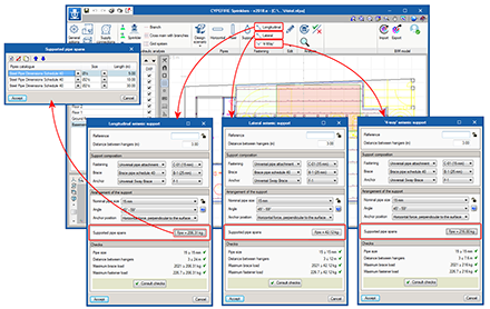
The NFPA 13 code classifies the seismic supports into 3 groups and can be introduced in CYPEFIRE Sprinklers from the “Support” menu of the toolbar:
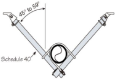
- Lateral support
Prevents movement in the direction perpendicular to the pipe. - Longitudinal support
Prevents movement in the direction parallel to the pipe. - 4-way support
Prevents movement in the 4 directions.
Before introducing them, the main components of the seismic supports must be defined: fastenings, braces and anchors. Users can define, amongst other catalogues, the catalogues for fastenings, braces and anchors in the “General options” dialogue (“General options” menu of the toolbar). Standard catalogues, which are included in the program, can also be used and imported into projects to use directly or modify with user values.
- Fastening
This is the element that holds the pipe to the brace. To define it, users must simply complete the dimensions of this element for each fastening of the catalogue.
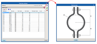
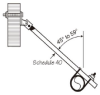
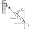
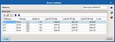
- Brace
This is the main element of the seismic support, consisting of a Schedule 40 pipe that has to resist the horizontal loads caused by the earthquake. To define it, users must introduce the length, diameter of the pipe and loads it can support at 30-44º, 45-59º and 60-90º.
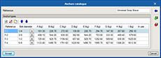
- Anchor
The anchor is the part that keeps the support connected to the structure of the building. In this version of the program, the limits that have been applied are those of anchors to steel structures. In upcoming versions, anchors to timber or concrete structures will be added. To define them, the diameter of the anchorage bolt and load the anchor can resist for each type of assembly must be introduced.
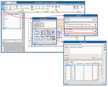
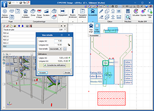
For CYPEFIRE Sprinklers to be able to carry out the required checks on seismic supports, the field “Weight per unit length” has been added to the pipe catalogues of the sprinkler systems (General options > Pipes catalogues) and the seismic coefficient Cp must be defined (General options > General data).
Once all the aforementioned elements have been defined, users must introduce each support that is going to be used at its corresponding position and define its influence zone, i.e. all the pipe spans that are to be held by each seismic support.
With the data indicated above, CYPEFIRE Sprinklers will ensure all the necessary checks are complied with for each type of support. The program generates the report required by the NFPA 13 code.
Improvements in the generated installation project format
The presentation format of the project has been modified. The results are now displayed in a more clear and concise manner. The report of the seismic supports that have been introduced in the model is also included.
CYPETHERM HVAC
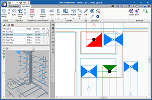
Vertical ducts
The introduction and design of vertical ducts has been implemented. From the properties panel, users can indicate up to what level they are to reach.
On plan, the direction of the flow in the vertical ducts is represented by a cross when it in a downward direction and a circle when the flow is in the upward direction.
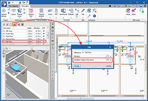
Floor heights and installation height
As of the 2018.e version, the height between floors and the elevation of each floor (which is obtained from the BIM model) are represented in the list of floor plans which is located in the top left of the program screen.
Furthermore, using the edit button of this list  , users can define the installation height of the ducts.
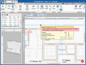
Warnings of flow in the wrong direction
Both horizontal and vertical ducts are introduced with an air flow direction which depends on the initial and final point when the horizontal ducts are drawn or the initial and final elevation in the case of each vertical duct. Using the “Invert the air flow direction in ducts” tool  , users can change the direction of flow.
As of the 2018.e version, if the direction of flow indicated by users is incorrect, the program detects this and emits a warning message at the end of the analysis process.
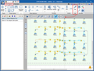
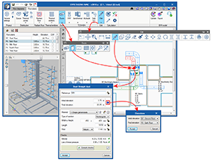
Copy format in circuit diagram
The “Assign” tool  has been added in the Flow diagrams tab of CYPETHERM HVAC. This way, users can quickly copy the length of one pipe to others. Once this tool is activated, the pipe whose length is to be copied is selected using the left mouse button and then, the pipes to which the length is to be assigned are selected with the same mouse button (one by one or using a capture window).
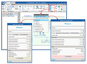
DAIKIN VRV systems
As of the 2018.e version, DAIKIN VRV systems can be introduced in the “Circuit diagram” tab. CYPETHERM HVAC generates a justification report of the designed system.
Arquimedes
Treatment of auxiliary prices as unit items depending on their decomposition
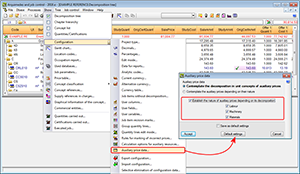
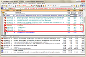
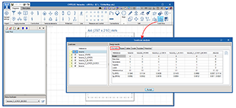
The option “Establish the nature of auxiliary prices depending on their decomposition” (Show > Configuration > Treatment of auxiliary prices) has been implemented, which allows for auxiliary prices that are composed exclusively of unit prices of the same nature (Labour, Machinery or Materials), take on that nature. Logically, these auxiliary prices can also include “Auxiliary measures”-type concepts (%-type concepts). This option establishes the nature condition of the auxiliary prices that comply with the condition, discriminating amongst the three nature types (Labour, Machinery or Materials).
Once this option has been activated, the affected auxiliary prices are recognised in the bill of quantities with the following icons:
 for labour auxiliary prices
 for machinery auxiliary prices
 for materials auxiliary prices
For example, in the image, the auxiliary price “Cuadrilla A” (Work group A), which is only composed of “Labour”-type unit items, can be recognised as a “Labour”-type unit price even though it has a decomposition.
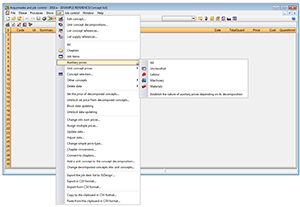
Additionally, the possibility to show auxiliary prices of those which have been assigned a “Labour”, “Machinery” or “Materials” nature has been added in the “Auxiliary prices” option in the List menu of the Concept list window.
Return to the 2018 version download area
Tel. USA (+1) 202 569 8902 // UK (+44) 20 3608 1448 // Spain (+34) 965 922 550 - Fax (+34) 965 124 950