Open BIM add-in for Revit
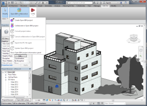
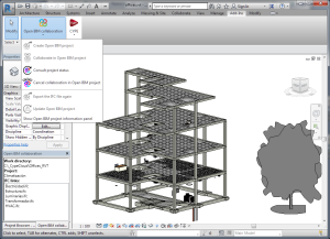
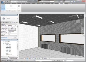
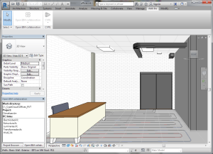
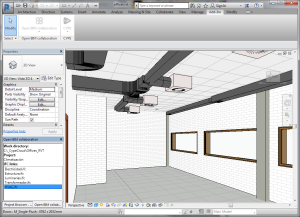
The 2017.f version of CYPE programs includes an add-in for Revit from AutoDesk©, which includes Revit in the Open BIM workflow.
Since CYPE initiated the integration of its programs in a collaborative, multidisciplinary and multi-user Open BIM workflow, applications of other software manufacturers have been able to participate in this project development system by interchanging information using IFC files.
With the Open BIM add-in for Revit, communication between Revit and CYPE’s group of specialised tools is improved. This way, the BIM workflow of projects modelled in Revit and analysed with CYPE programs, is optimised.
The following sub-sections describe the improvements this CYPE add-in provides for Revit:
- Open BIM workflow
- Project modification updates
- Automatic configuration of the export to IFC from the add-in
- Collaboration in the cloud (BIMserver.center®)
Features of the Open BIM add-in for Revit
Open BIM workflow
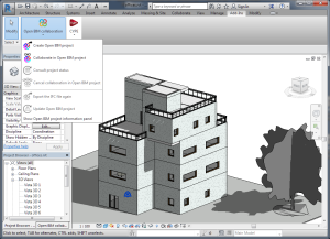
With the "Open BIM add-in for Revit", users can directly begin an Open BIM project in Revit. This way the architectural model can communicate with CYPE's simulation programs, and so achieving a two-way collaboration in real time amongst the various disciplines of the project and Revit using IFC interchange files. This collaboration can be carried out locally (the IFC files making up the project are in a local or internal network directory) or in the cloud (using the BIMserver.center® platform).
Project modification updates
CYPE's Open BIM add-in for Revit informs Revit users of the modifications that have been generated in the projects of the different disciplines, allowing them to decide whether to update the information of the project or not. Without this add-in, i.e. with only the direct link to Revit using IFC format files, users must update the project in Revit.
Automatic configuration of the export to IFC from the add-in
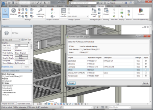
The export process to an IFC file using the Open BIM add-in for Revit, automatically optimises the IFC file that is generated so that CYPE programs can interpret it correctly, as long as the modelling of the project in Revit has also been introduced correctly.
Collaboration in the cloud (BIMserver.center®)
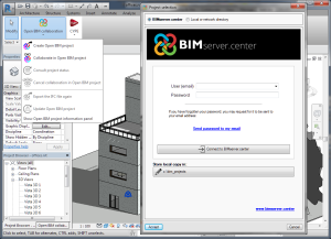
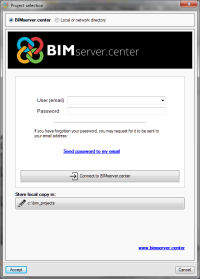
Using CYPE's Open BIM add-in for Revit, the Autodesk application can use the BIMserver.center® service directly. "BIMserver.center®" is a service managed by CYPE to save, synchronise and share BIM project files. This service offers:
- Safe storage in the cloud of BIM project files. All intervening agents can access it from any device and share them in a coordinated manner.
- Acts as a collaboration platform to centralise all files in real time.
- Optimises BIM workflow and communication amongst professionals.
- Until now, only CYPE programs could use the BIM storage service for projects. Now Revit, using the new Open BIM add-in created by CYPE can also use this service, regardless of whether or not there is a connection to other CYPE programs.
Installation of the Open BIM add-in for Revit
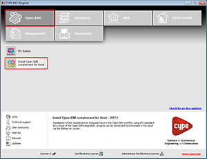
Users can install the Open BIM add-in for Revit the CYPE program menu, by selecting the Install Open BIM add-in for Revit tool.
To be able to install the add-in, Revit (2015 version or higher) must be installed on the same computer where the add-in installation will be executed.
User license
The "Open BIM add-in for Revit" is a free access application. Logically, for it to operate users must hold a Revit user license (2015 version or higher, with the IFC 2015 or IFC 2016 add-in – higher versions of Revit already include this add-in).
If users also wish to include their Revit projects in the Open BIM workflow with CYPE programs, they must hold a CYPE program user license (2017.f version or higher), which includes the programs on which they wish to collaborate.
Code implementation and improvements in its application
Timber structures
ANSI/AWC NDS – 2015 (EEUU)
National Design Specification for Wood Construction.
Implemented in CYPECAD and CYPE 3D.
CIRSOC 601 (Argentina)
Reglamento Aregentino de Estructuras de Madera
Implemented in CYPECAD and CYPE 3D.
Loads on structures. Wind loads
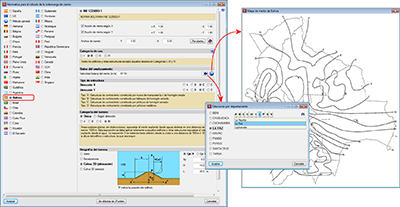
NB 1225003-1 (Bolivia)
Norma Boliviana NB 1225003-1
Implemented in CYPECAD.
CYPECAD
Contour map representation improvements
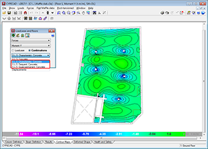
Representation of the S.L.S. of force combinations
As of the 2017.f version, CYPECAD can represent Serviceability Limit State (S.L.S) force combinations in its contour maps.
Contour interval representation
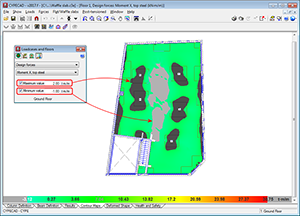
In the contour maps for “Design forces”, “Steel areas” and “Ground bearing pressures”, users can define limits, so zones with values exceeding them are not displayed. In previous versions, zones whose values exceeded the limits were shown in the colour of the limit values. As of the 2017.f version, the zones exceeding the maximum limit are shown in dark grey and the zones below the minimum limit in light grey. This allows users to clearly distinguish the zones exceeding each limit.
Diagram of average values between two points
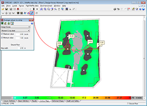
In previous versions, the “Average values in a strip” diagram (which can be defined in the Contour Maps tab), was not drawn when it passed through contour zones with values exceeding the limits established by users.
As of the 2017.f version, this diagram is also represented when it passes through these zones, which are currently displayed in grey (see previous new feature: “Contour interval representation).
Punching shear reinforcement quantities
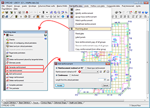
Punching shear reinforcement that is introduced using the “Generate reinforcement” or “Add reinforcement” options (Results > Slabs/Waffle slabs > Punching shear) is measured in the takeoff report (File > Reports > Job takeoffs).
CYPETHERM HVAC
Radiant floor
Polytherm radiant floor
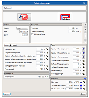
As of the 2017.f version, Polytherm radiant floor systems are incorporated in the program. Users can now select any of the systems offered by Polytherm in their current catalogue.
Circuit and manifold tags
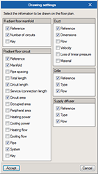
Users can now configure the tags of the radiant floor circuits and manifolds. This way, users can decide what data is to be included in the tags generated by the program (they are displayed on screen and on the installation plans) for these elements of the installation.
CYPETHERM EPlus
Lighting and unoccupied precinct equipment
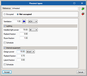
When defining precincts that are “Not occupied”, the definition of lighting and internal equipment is included. This way, the simulation can be carried out of unoccupied precincts with high interior gain, which may affect the energy performance of the adjacent residential precincts.
Return to the 2017 version download area
Tel. USA (+1) 202 569 8902 // UK (+44) 20 3608 1448 // Spain (+34) 965 922 550 - Fax (+34) 965 124 950
