- New programs
- Code implementation and improvements in its application
- CYPECAD
- IFC Builder
- StruBIM Design
- StruBIM Analysis
- CYPELUX and CYPELUX CTE
- CYPESOUND and CYPESOUND CTE
- CYPETHERM LOADS and CYPETHERM EPlus
- CYPECAD MEP, CYPETHERM HE Plus and CYPETHERM EPlus
- CYPETHERM HVAC
- Return to the 2017 version download area
New programs
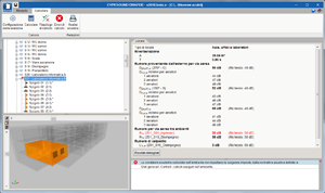
StruBIM Foundations (USA)
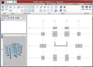
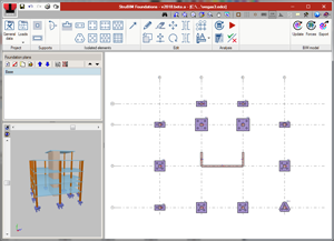
StruBIM Foundations is a tool to design foundations. With the supports of the structure, users can generate, design and check the foundation elements.
This tool is integrated in CYPE’s Open BIM workflow via IFC standard. Users can also import files in XML format.
Initially, StruBIM Foundations designs and checks foundations in accordance with the following codes: ACI 318-14, ACI 318-11 and ACI 318-08.
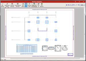
It generates drawings containing the on-plan view of the foundations and the description tables of the footings, pile caps and piles used.
More information can be found on the "StruBIM Foundations" webpage.
CYPETHERM RECS Plus (Portugal)
New program to justify the Portuguese code: “Regulamento de Desempenho Energético de Comércio e Serviçios (RECS)” using a model of the building to carry out its energy simulation with EnergyPlus™.
CYPETHERM RECS Plus is integrated in the Open BIM workflow via IFC standard.
More information (in Portuguese) is available on the “CYPETHERM RECS Plus” webpage.
CYPESOUND DRAPDE (Italy)
Design and verification of sound insulation for airborne and impact noise, sound immissions and reverberation level, in accordance with the D.P.C.M. 5/12/1997 (Determinazione dei requisiti acustici passive degli edifici). This application is integrated in the Open BIM workflow via IFC standard.
More information (in Italian) is available on the “CYPESOUND DRAPDE” webpage.
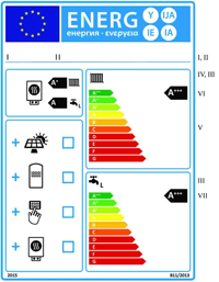
CYPETHERM Etichetta Energetica (Italy)
Provides the energy certification for heating and hot sanitary water equipment. In accordance with the Regolamenti Delegati (UE) 811/2013 and 812/2013 de la Comissione Europea, the program generates the energy certificate, product sheet and technical dossier for the equipment.
More information (in Italian) is available on the “CYPETHERM Etichetta Energetica” webpage.
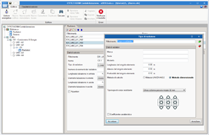
CYPETHERM Contabilizzazione (Italy)
CYPETHERM Contabilizzazione is a program designed to carry out the distribution of the heating and hot sanitary water costs in multi-family residential buildings. CYPETHERM Contabilizzazione allows users to calculate the parts per thousand of the demand or thermal power installed in homes, in accordance with UNI 10200:2015, and generates all the reports of Appendix C of the code.
More information (in Italian) is available on the “CYPETHERM Contabilizzazione” webpage.
Code implementation and improvements in its application
Concrete structures
NB 1225001 (Bolivia)
Norma Boliviana. Hormigón Estructural
Implemented in CYPECAD and CYPE 3D.
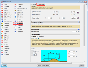
Loads on structures. Wind loads
REP-2014 (Panama)
REP-2014. Reglamento Estructural de Panamá.
Implemented in CYPECAD.
Loads on structures. Seismic loads
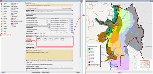
Microzonation of Cali (Decree 411.0.20.0158 of 2014)
As of previous versions, when users selected to carry out a seismic analysis with the NSR-10 code (Colombia), they could choose amongst several microzonations:
- Bogotá D.C.
- Cali (2005)
- Pereira
As of the 2017.e version, the Microzonation of Cali of 2014 has been included (Decree 411.0.20.0158 of 2014).
CYPECAD
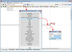
Divide column
The option, “Divide column”, which divides a column into two parts has been implemented in the “Columns, shear walls and starts” menu (Column Definition tab > Introduction). The option divides columns in such a way that the start of the column above is the top of the one below.
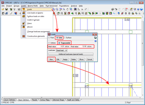
Linear trapezoidal load
As of the 2017.e version, CYPECAD allows users to define linear trapezoidal loads.
IFC Builder
External precincts
As of the 2017.e version, users can define external precincts.
StruBIM Design
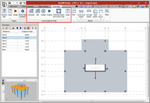
Local analytical models of floor drawings
Introduction
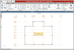
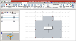
Local analytical models of the floor plans can now be generated, edited and analysed, with the 2017.e version. The local models allow for a floor of the global model to be analysed independently from the rest of the floors, improving the flexibility during the structural analysis. The design of the structural elements of the floors can be carried out with the forces of one model or another.
Generation
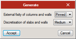
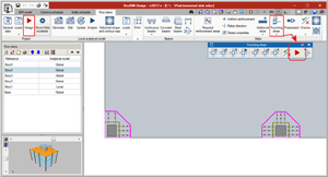
To generate a local model, select the “Generate” icon. There are several possible situations that affect the generation process:
- Generation of local analytical models in projects without an associated BIM model
This type of project has been created without the help of an IFC or XML file from the start, or it has been created using an IFC or XML file but the link with the BIM model has not been kept. In these cases, when users click on “Generate” a panel appears where the type of external fixity to be assigned to columns can be selected, as well as the discretisation size for slabs and walls.
The floor plans of this type of projects generate an analytical model composed of floor slabs, beams, columns and walls defined on plan. Neither loads, loadcases, nor combinations are generated. Columns and beams generate bars, and slabs and walls generate finite element shells. - Generation of local analytical models in projects with an associated BIM model
This type of project has been created based on an XML or IFC file. Regardless of whether a global analytical model has been defined or not, the floor plans of this type of project generate an analytical model based on the BIM model of the floor.
If a global analytical model exists (imported using an XML file or from a results file exported from StruBIM Analysis), the model that is generated will contain a group of loadcases and load patterns equivalent to those of the global model and one or more combination groups of these loadcases. Loads, displacements and fixities are generated in accordance with the type of model that is selected by users amongst the following:
- Only with floor loads
In this case, a model is generated with the beams and slabs defined on the floor plan and the spans of columns and walls that reach that floor. The wall spans that stat at that floor generate a beam with the same section as the wall. Regarding loads, the loads defined in the corresponding floor of the global analytical model are generated. - Floor loads and elements starting on the floor
In this case, a model is generated with the beams and slabs defined on the floor and the column and wall spans that reach that floor. The wall spans that start on that floor generate a beam with the same section as the wall. Regarding the loads, the program generates the loads defined in the corresponding floor of the global analytical model and the loads reaching the floor from elements on higher floors which bear their loads on that floor. - Floor loads, elements starting on the floor and displacements of the supports
In this case a model is generated with the beams and slabs defined on plan. The spans of the columns below generate a support, which is fixed or pinned depending on what users select. Regarding loads, the program generates the loads defined in the floor in the global analytical model, the loads reaching the floor from elements on higher floors which bear on that floor, and the displacements of the columns of the global model by loadcase such as displacements prescribed at the supports, as well as the corresponding loadcases and load patterns.
- Only with floor loads
If the global analytical model is not available, the model that is generated will be that of the first case, but without any information of the global model. In all cases, non-deformable zones at the top of columns will be generated as will the necessary trims at column and beam ends due to the dimensions of the nodes.
Editing
To edit a local model, the “Edit” button must be selected. The editing process of the model is carried out using an interface similar to that of StruBIM Analysis, where users can edit the discretisation size of the shells, fixity coefficients, stiffness factors, mechanical properties of the bars, acting loads...
Updating
The local analytical model can be updated in two ways:
- Using the “Update” option in the floor plans tab
In this case, this option transfers the thickness of the slabs, beam sections and materials from both elements to the analytical model. For elements whose properties are not the same, StruBIM Design displays a warning sign. - When the global BIM model is updated
In this case, the local analytical models of the floor plans that have been defined, are updated. If only the forces of the global model are updated, StruBIM Design will update the loadscases, load patterns, loads and displacements of the local analytical model.
Management of the local model for the comparison and design of elements
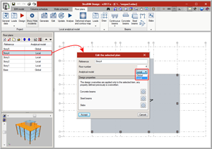
Once the local analytical model has been generated for a floor plan, the forces of the model will be used, by default, to design and check all the elements contained in the plan. Using the “Edit” option from the floor plans list, users can indicate they wish to use the global analytical model again for all the elements of the plan.
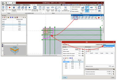
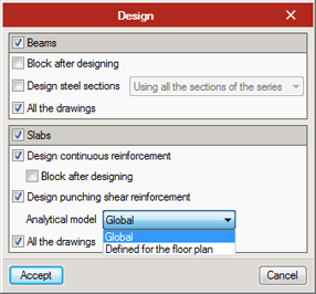
Floor slabs are always designed and checked using the local analytical model defined for the floor plan. When there are floor plans with a local analytical model, StruBIM Design allows users to indicate, for beams and punching shear zones, whether the local or global analytical model is to be used.
Results consultation
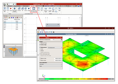
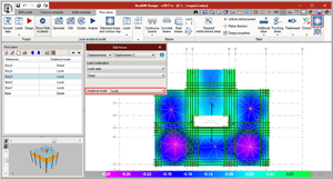
The results from the analysis of the local model can be viewed in the Deformed shaped and contour maps window, and from the Slab forces and Beam forces windows.
It is possible to alternate between the view of the forces of the global model and the local model. As well as the forces, the displacements and stresses can be consulted.
Post-tensioned slabs
Introduction
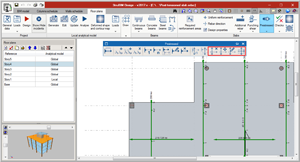
Implemented in the 2017.e version is the design of post-tensioned slabs. This improvement has been created to design the passive reinforcement of post-tensioned slabs, having calculated the forces in the post-tensioning tendons (adherent or non-adherent), and whose properties have been introduced by users.
Users can introduce the path of the tendons, their definition, their stressing loads and their losses (instantaneous and differed). The program generates two post-tensioned load patterns (one with the instantaneous loss and another with the total loss) in which the deviation loads, due to the path of the tendons are introduced. The program also creates three loadcases, two equivalent to the previously mentioned load patterns, and one hyperstatic loadcase with the total loss.
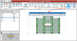
Due to the path of the tendon, forces are produced acting towards the inside of its curvature. The program automatically generates these loads for each tendon. These loads will affect the floor slabs when the local model of that floor plan is analysed. The discretisation of the floor slab during the local analysis is carried out using triangular finite elements which are adjusted to the path of the tendons.
The post-tensioning effect is taken into account when calculating the reinforcement areas required in the slab. When a tendon crosses a critical punching shear perimeter, its effect is taken into account.
Floor slabs containing tendons will be checked and will be designed as post-tensioned slabs in accordance with the ACI 318-14, ACI 318-11 and ACI 318-08 codes.
Generation of loadcases and combinations
In the dialogue box that appears when generating a local model, users can select to automatically generate post-tensioned load patterns. By activating this option, the post-tensioned load patterns, loadcases and combination groups are generated.
- Load patterns
PT Transfer with the instantaneous losses and PT Final with the total losses (instantaneous plus differed) in which the deviation loads produced by the path of the tendons will be introduced. - Loadcases
Three loadcases are created, one equivalent to each of the previously mentioned loadcases and a third hyperstatic loadcase with the total loss. - Combination groups
Four combination groups are created: PT Flexural strength (Ultimate), PT Service (Initial), PT Service (Normal) and PT Service (Long term). Each post-tensioned state will be assigned one of these combination groups.
Implemented tools
- Flexure lines
The intersections, on plan, of the flexure lines with the paths of the tendons represent the points where the tendon curves to reach its maximum elevation.
Flexure lines can be introduced between two points and on reference lines.
- Tendon introduction
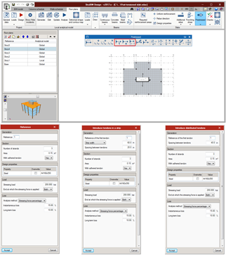
There are several tendon introduction options: Introduction of a single tendon, introduction of concentrated tendons and introduction of distributed tendons. The difference between these options lies in the way the number of tendons that have to be introduced are defined.
- One tendon
One tendon is introduced between two points. - Concentrated tendons
Users indicate the spacing between the tendons and how many there are, or the strip width. - Distributed tendons
Users indicate the spacing between tendons. Once the dialogue box has been accepted, the path of the tendons is defined graphically, and the strip width along which they are to be placed.
- One tendon
With each of these options, users can define:
- Section
Number of strands, their cross-sectional area and their type (adherent or non-adherent). - Tendon material
- Load
Transfer load pattern, final load pattern, stressing load and end at which the stress is being applied. - Stressing loss
Three options appear to define the stressing loss: - Stressing force percentage
- Specified value
- Detailed analysis, based on the friction coefficient due to the curvature, friction coefficient due to accidental deviation, spacer penetration, loss due to elastic shortening of the concrete, loss due to creep of the concrete, loss due to concrete shrinkage and loss due to steel relaxation.
- Tendon schedule
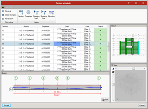
The different properties of the tendons can be edited in the tendon schedule (previously defined during the introduction), as well as the elevations.
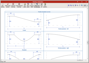
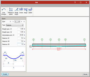
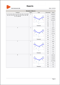
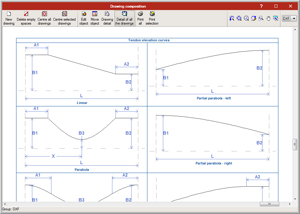
By editing the diagram, users can modify the path of the tendons on the elevation view of the slab. There are several types of elevations that can be assigned to each tendon span:
- Linear
- Parabola
- Reverse parabola
- Harped one point parabola
- Harped two point parabola
- Partial parabola - left
- Partial parabola - right
- Partial rev. parabola - left
- Partial rev. parabola - right
- Representation tools
The tendon groups (concentrated or distributed) can be represented as being grouped or ungrouped. There are label management tools, in case users choose to represent the tendons as grouped. These tools allow user to add, edit, move, and delete labels as well as select the visible tendon of the group.
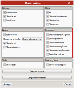
- View options
From the Draw menu, users can access the View options, where several options have been added to view prestressed related elements.
Results output
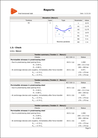
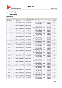
Different reports are generated indicating the properties, elevation geometry and checks of the tendons.
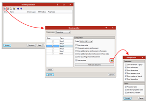
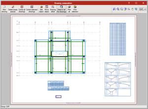
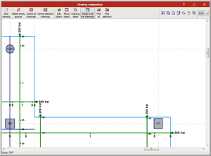
The program also generates floor plans with the tendon distribution and dimensions selected by users in the drawing configuration. Users can also include the Properties table, the elevation properties table and elevation curves table.
Punching shear reinforcement design
Design
The program now automatically designs punching shear reinforcement. In previous versions, the critical punching shear perimeter was only generated for columns or column groups that were not in contact with beams. During the design process, the program regenerates and automatically checks the critical punching shear sections. The design process can be executed from the Punching shear menu (affects only the selected floor) or from “Project > Design” (affects the selected plan or all plans).
The design of all the punching shear reinforcement can be carried out using the forces of the global analytical model or those of the analytical model defined for the floor plan.
Design options
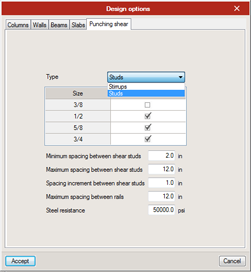
The punching shear reinforcement can be designed using shear studs or stirrups. The type of reinforcement can be selected before the design process begins in “General data > Design options > Punching shear”.
Column design options
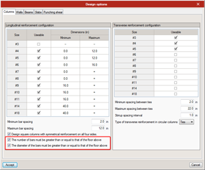
Two new design options for columns have been implemented:
- The number of bars must be greater than or equal to that of the floor above.
- The diameter of the bars must be greater than or equal to that of the floor above.
By activating these options, the number of bars remains the same or is reduced on higher floors, and the diameter of the bars remains the same or is reduced on higher floors.
User warnings
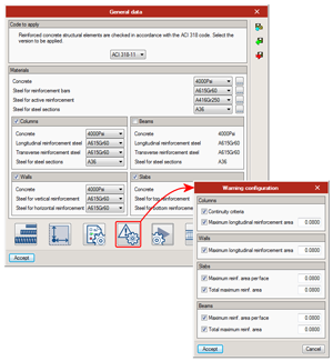
Users can configure the program to generate additional warnings to those provided by the code.
In columns, if the “Continuity criteria” option is activated, a warning is generated for each column span when the number or the diameter of longitudinal bars is less than that of the span above.
For columns, walls and beams, users can indicate for a warning to be generated if a certain steel reinforcement area, defined by them, is exceeded. This is an additional warning or check to those required by the code.
Import reference lines
Users can now import reference lines which make up a grid during the creation process of the project using a BIM model.
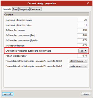
Check shear outside the plane in walls
The option to check shear outside the plane in walls is not obligatory; in previous versions, it was.
When users indicate for it to not be checked, the check report of the wall will indicate the acting shear, the shear resistance of the concrete section of the wall, and if necessary, the required reinforcement area.
StruBIM Analysis
Hyperstatic analysis
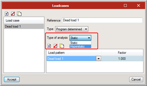
As of the 2017.e version, a new attribute has been added to loadcases: the “Type of analysis”.
Users can select between a static analysis or hyperstatic analysis. In previous versions, a static analysis was carried out for each loadcase. The hyperstatic analysis is required when structures are designed with post-tensioned slabs. Even though users can choose to carry out a hyperstatic analysis for any loadcase, this type of analysis is logical when there is equilibrium amongst loads that are introduced, as occurs with post-tensioned cases, since the supports of the structure are eliminated.
Non-deformable zones
Users can define non-deformable zones in shells. When a non-deformable zone is introduced on a shell, there is the hypothesis that that part of the shell is infinitely rigid. Non-deformable zones can be used to simulate the size of nodes. When a local analytical model is generated from StruBIM Design, a non-deformable zone is placed at the support of each column, with the same size as the column.
Calculation of node dimensions during the model import process
The program now calculates the dimensions of nodes during the import phase of a model. Trims at bars with the same size as the nodes, are assigned. By default, the trims at ends have an assigned stiffness zone factor equal to zero.
Shell stiffness factors
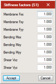
Users can define factors that modify the stiffness of shells. Using these factors, the axial, bending and shear stiffness can be modified, for the local axes of the shell.
Shell eccentricity
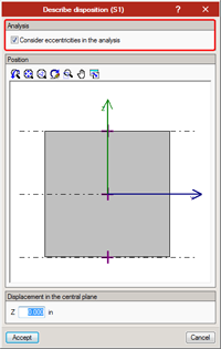
When the layout of shells is defined, users can choose whether or not to consider the eccentricity of the shell during the analysis of the forces.
Menu reorganisation
The program menus have been reorganised. The options and buttons of the program have been groups into three menus or tabs: Geometry, Loads and Analysis:
- Geometry
Contains the element introduction and editing options for elements, and properties of nodes, bars and shells. - Loads
Contains the load introduction and editing options. - Analysis
Allows users to consult and export results.
Simultaneous editing and analysis of various projects
As of the 2017.e version, users can open and analyse several StruBIM Analysis projects simultaneously.
CYPELUX and CYPELUX CTE
These new features have also been implemented in CYPELUX RECS (Portugal).
New analysis motor (Radiance)
As of the 2017.e version, CYPELUX uses the Radiance analysis motor (developed by the Lawrence Berkeley National Laboratory) to carry out the lighting analyses for normal and emergency lighting. This new analysis methodology provides more precise results for indirect lighting, carry out the discretisation of non-point light sources and view realistic light scenes.
Scene rendering
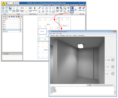
Thanks to the inclusion of the Radiance analysis motor in CYPELUX, users can represent the lighting effects produced by the installation of normal or emergency lighting on a precinct.
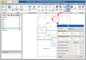
To do so, the View option has been added to the program. This option contains three new buttons:
- New view
It is possible to introduce different points of view on the floor plan and configure its properties.
- Render
Using this option, users can indicate which view is to be rendered.
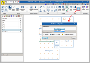
- Rendering configuration
When rendering takes place, users can choose whether the lighting to be viewed is normal (internal and external) or emergency lighting, as well as the degree of precision of the scene.
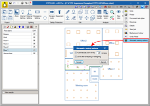
Autosave
The autosave option has been implemented in the 2017.e version of CYPELUX. The autosave can be carried out in two ways:
- Automatically save every... minutes
Save the project automatically in the indicated time interval. - Save after analysing or designing
Save the project automatically upon analysing the lighting installation.
Neither option is activated by default. Hence, users must activate the option they wish to apply.
CYPESOUND and CYPESOUND CTE
Sound of the openings of air conditioning ducts
As of the 2017.c version, CYPESOUND and its specific versions for some countries, import, from a BIM model, the noise produced by the openings of ventilation systems. Users then had to specify the other properties that specify the noise produced by these openings in a precinct.
As of the 2017.e version, CYPESOUND, CYPESOUND CTE (Spain), CYPESOUND RRAE (Portugal), CYPESOUND NRA (France) and CYPESOUND DRAPDE (Italy), automatically calculate the following parameters: “r” (radius of the largest sphere that can be inscribed in the precinct) and “D” (directivity factor of the source) of the grilles and diffusers. This way, the noise generated by the HVAC duct networks in the precincts can be obtained more easily.
The analysis is carried out during the import process of these elements, based on IFC files, hence the CYPESOUND project must import them from the BIM model (either because the project is linked to a BIM model or, if it is not, because the BIM model has been imported without maintaining the link). Logically, the imported BIM model must include the design of the duct installation for heating, ventilation and air conditioning. CYPETHERM HVAC allows users to export these installations to the BIM model.
CYPETHERM LOADS and CYPETHERM EPlus
Edge management
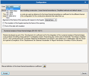
The 2017.e version of CYPETHERM LOADS and CYPEHERM EPlus has improved edge management. As of the 2017.e version, users can choose the code with which edges are to be analysed, so they can be detected as being thermal bridges (ISO 14683, ISO 14683- Italy, HE1 2006, HE1 2013, RT2005/2012 and REH).
This improvement has also been included in CYPETHERM RT2012 (France) and CYPETHERM RTExistant (France).
CYPECAD MEP, CYPETHERM HE Plus and CYPETHERM EPlus
EnergyPlus 8.6 analysis motor update
In the 2017.e version, CYPE has updated the EnergyPlus™ analysis motor in all the programs which use it: CYPECAD MEP, CYPETHERM HE Plus and CYPETHERM EPlus and the new CYPETHERM RECS Plus. This way, CYPE uses the latest version that is available of the analysis motor of the US Department of Energy (DOE): version 8.6, published on 27th September 2016.
CYPETHERM HVAC
BIM model
Import columns, doors and windows
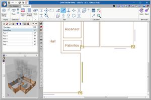
Columns, doors and windows defined in the IFC model are now imported to CYPETHERM HVAC. This feature not only aids in understanding the architectonic model on which the installations are being designed, but they are also taken into account when inserting air conditioning equipment.
Radiant floor
Detection of doors and columns of the BIM model during the automatic generation of the radiant floor
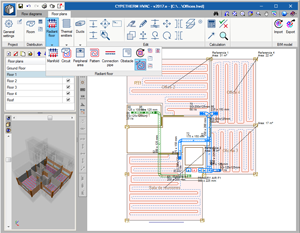
As of previous versions, using the “Generate circuits” button, the program detects all the spaces for which a design heating temperature has been defined, and automatically generates the radiant floor circuit. As of this version (2017.e), the generating process interprets that the columns in the BIM model are obstacles and the doors are an entry point for the pipes of the radiant floor.
Remember, once the radiant floor has been generated, the installation must be designed so the program can calculate the area and power generated by each circuit.
Manifold flow meters
Users can use flow meters in the hydraulic balancing of the manifolds of the radiant floor; only balancing valves were available up to now.
Circuit-manifold connection pipes
The behaviour of the connection pipes of the radiant floor (from the circuit to the manifold) has been improved. Now, the thermal contribution in the precinct through which these pipes go through is accounted for and graphical representation problems have been solved.
Thermal emitters
Detection of windows of the BIM model during the automatic generation of radiators
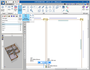
In the 2017.e version, the “Generate thermal emitters” option has been implemented. If this button is selected, the program provides a radiator below each window, by default, thanks to the interpretation of the BIM model.
The radiators that are placed are not designed. It is not until users press the design button that the program will select the number of elements each radiator requires to cover the heating thermal load.
Description of the thermal parameters of the emitters
The definition of the thermal emitters has been simplified by substituting the “average temperature”, which was indicated up to now, with the entry and outlet temperatures.
Internal design temperature in the emitters
The thermal emitters adopt the internal design temperature of the precinct in which they are located. Users can block this temperature in the emitters.
Ducts
Configuration of the generation of duct fittings
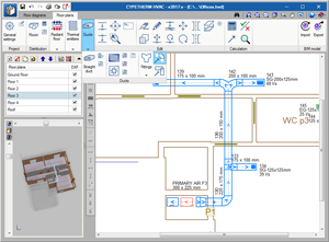
When users select the “Generate fittings” button, a new dialogue appears where the generation process of the duct ties can be configured:
- Delete existing fittings
By selecting this option, any fittings that were placed before the generating process are deleted. The new fittings are generated in accordance with the dimensions of the spans they have to connect. - Generate in all the floor plans
Intersections between ducts and columns
If there are any intersections between the columns of the BIM model and the ducts of the installation, the program will warn users with an error message.
Return to the 2017 version download area
Tel. USA (+1) 202 569 8902 // UK (+44) 20 3608 1448 // Spain (+34) 965 922 550 - Fax (+34) 965 124 950
