
(30th October 2013)
![]()
- Code implementation and improvements in its application
- CYPECAD
- Eurocode 2 (EU, France and Portugal) in the advanced beam editor
- Seismic design
- Reinforcement ductility criteria and capacity design criteria for seismic design for the combination of Eurocode 2 concrete code (EU, France and Portugal) and Eurocode 8 seismic code (EU, France, Portugal and Belgium)
- Fundamental period of the structure with user values for NSR10 (Columbia) and NC 46:1999 (Cuba)
- Dimensions and effective mechanical steel areas of slabs for capacity checks of concrete columns and beams
- Maximum size and nature of the aggregate
- Reduction of the concrete resistance of columns
- Axial stiffness coefficients for columns, shear walls and walls
- Reduction of reinforcement anchorage and splice lengths in columns, only for bars in tension
- Advanced beam editor
- Improvements in the work environment
- Dropped rectangular beams with variable sections
- Divide a bar pack (change the layer of some of the bars of a pack)
- On-screen consultation of the required and effective areas of the reinforcement of a frame
- Representation of the floor slab in the transverse sections of beams in the frames drawing
- Drawing of secondary beams in the frames drawing
- Strut3D
- CYPECAD MEP
- Improvements in the work environment of CYPECAD MEP
- Floating tool windows and their tools
- Appearance of the floating windows
- Visibility of the floating windows (keep visible or hide automatically)
- Distribution of the tools of the floating windows along the sides of the display
- Memorisation of the position, appearance and visibility of the floating windows
- Thermal analysis for France
- Thermal analysis for Italy
- Selection of heating or sanitary hot water systems with several generators acting in series
- Selection of heating or sanitary hot water systems with several accumulators (generators in series with a shared accumulator or generators with an independent accumulator)
- Selection of heating or sanitary hot water systems with a heat pump to carry out the thermal analysis
- Selection of heating systems with cogeneration to carry out the thermal analysis
- Selection of auxiliary heating or sanitary hot water generation systems using solar thermal collectors to carry out the thermal analysis
- Selection of photovoltaic collectors to carry out the thermal analysis
- Air conditioning
- “ASHRAE Weather Data Viewer 4.0” climate database
- Radiant floor. Automatic and manual selection of the most unfavourable circuit
- Radiant floor. Optimisation of the analysis of the power provided by each circuit
- Electricity (Brazil, Spain and Portugal)
- Arquimedes
- Return to the 2014 version download area
Code implementation and improvements in its application
Concrete code
ABNT NBR 6118 Projeto Junho 2013 (Brazil)
Projeto de estruturas de concreto – Procedimiento
This document is a project revision of the ABNT NBR 6118 2007 code, which is currently not in force, however it is foreseen that it will substitute the current standard.
It has been implemented in CYPECAD (including Strut3D) and Metal 3D.
Eurocode 2 (EU, France, Portugal)
- Eurocode 2 (EU)
Design of concrete structures. EN 1992-1-1:2004/AC 2008
- Eurocode 2 (France)
Calcul des structures en béton. NF EN 1992-1-1:2005/NA: Mars 2007
- Eurocode 2 (Portugal)
Projecto de estruturasdebetão. NP EN 1992-1-1:2010/NA
These codes were already implemented as of previous versions. They were also included, in previous versions, in the group of codes which use CYPECAD’s advanced beam editor (which implies that as well as the advantages obtained from using this editor, detailed Ultimate Limit State reports and reinforcement tables can be automatically generated) ![]() .
.
Now, as of the 2014.d version, when the selected concrete code is Eurocode 2 (EU), Eurocode 2 (France) or Eurocode 2 (Portugal), beams are edited using CYPECAD’s advanced beam editor. This implies important improvements in the application of these codes:
- Detailed U.L.S. and S.L.S. check reports for concrete beams (including check for failure due to torsion)
- U.L.S. and S.L.S. reports for steel beams
- Graphs and numerical values of the required and effective reinforcement areas
- Bar bending diagrams and reinforcement detailing configurations for frame drawings
- Design of dropped beams with a variable section
- And generally provides a graphical interface to edit the resistance elements of the frame (reinforcement, steel sections, lattices etc.) that is quick and easy to use.
More information can be found in the “Advanced beam editor” section on the webpage dedicated to concrete beams in CYPECAD ![]() .
.
If an analysis with seismic loads is carried out, each one of the Eurocodes; Eurocode 2 (EU), Eurocode 2 (France) and Eurocode 2 (Portugal), has a corresponding set of seismic codes with which it is compatible, and allow for CYPECAD’s advanced column and beam editors to be used, taking into account their capacity design criteria to design concrete beams and columns:
- Eurocode 2 (EU)
- Eurocode 8 (EU)
EN 1998-1. Eurocode 8: Design of structures for earthquake resistance. Part 1: General rules, seismic actions and rules for buildings. - Eurocode 8 (France)
NF EN 1998-1/NA (2007) Eurocode 8: Calcul des structures pour leur résistance aux séismes.Partie 1 : Règles générales, actions sismiques et règles pour les bâtiments Annexe nationale à la NF EN 1998-1:2005.1 - Eurocode 8 (Portugal)
NP EN 1998-1 (2010). Eurocódigo 8 - Projecto de estruturas para resistência aos sismos. Parte 1: Regras gerais, acções sísmicas e regras para edifícios. - Eurocode 8 (Belgium)
NBN-ENV 1998-1-1: 2002 NAD-E/N/F Eurocode 8: Conception et dimensionnement des structures pour la résistance au séisme. Partie 1-1: Règles générales. Actions sismiques et exigencies générales pour les structures - PS 92 (France)
Règles de Construction Parasismique - Règles PS applicables aux bâtiments – PS 92. - PS 92 (version révisée 2010) (France)
Règles de Construction Parasismique - Règles PS applicables aux bâtiments – PS 92 (version révisée 2010). - RPA 99/v 2003 (Algeria)
Règles Parasismiques Algériennes RPA 99 / VERSION 2003. - RPS 2000 (Morocco)
Règlement de Construction Parasismique. - RPS 2011 (Morocco)
Règlement de Construction Parasismique (version révisée 2011). - 1997 UBC (USA)
Uniform Building Code. - 2009 IBC (USA)
International Building Code.
- Eurocode 2 (France)
- Eurocódigo 8 (Francia)
NF EN 1998-1/NA (2007) Eurocode 8 : Calcul des structures pour leur résistance aux séismes. Partie 1 : Règles générales, actions sismiques et règles pour les bâtiments Annexe nationale à la NF EN 1998-1:2005.1 - PS 92 (France)
Règles de Construction Parasismique - Règles PS applicables aux bâtiments – PS 92. - PS 92 (version révisée 2010) (France)
Règles de Construction Parasismique - Règles PS applicables aux bâtiments – PS 92 (version révisée 2010). - RPA 99/v 2003 (Algeria)
Règles Parasismiques Algériennes RPA 99 / VERSION 2003. - RPS 2000 (Morocco)
Règlement de Construction Parasismique. - RPS 2011 (Morocco)
Règlement de Construction Parasismique (version révisée 2011). - 1997 UBC (USA)
Uniform Building Code. - 2009 IBC (USA)
International Building Code.
- Eurocódigo 2 (Portugal)
- Eurocode 8 (Portugal)
NP EN 1998-1 (2010). Eurocode 8 - Projecto de estruturas para resistência aos sismos
Parte 1: Regras gerais, acções sísmicas e regras para edifícios. - 1997 UBC (USA)
Uniform Building Code. - 2009 IBC (USA)
International Building Code.
The concrete and seismic codes that are available for the capacity design criteria for concrete columns and beams can be found in the “Capacity design criteria for seismic design of concrete columns and beams” section on the CYPECAD webpage ![]() .
.
More information can also be found in the “Design codes available for use with the Advanced beam editor” section on the Concrete beams webpage ![]() .
.
Loads on structures. Seismic loads.
Reinforcement ductility criteria and capacity design criteria for seismic design for Eurocode 8 (EU, France, Portugal and Belgium)
When an analysis is carried out in CYPECAD using any of the indicated seismic design codes, combined with Eurocode 2 (EU), Eurocode 2 (France) and Eurocode 2 (Portugal), the program takes into account the reinforcement ductility criteria and the capacity design criteria for seismic design of the selected seismic code. These criteria are justified in the Ultimate Limit State reports generated by the advanced column and beam editors of CYPECAD.
More information on the combined use of these concrete and seismic codes can be found in the “Eurocode 2 (EU, France and Portugal)” section on this webpage ![]() .
.
ASCE 7-10 (USA)
Minimum Design Loads for Buildings and Other Structures.
Implemented in CYPECAD and Metal 3D.
Users can choose to CYPECAD carry out the dynamic analysis (modal spectral) or static analysis (equivalent lateral force) proposed by the ASCE 7-10 design code. The analysis method (dynamic or static) is selected using the Analysis method option within the dialogue box where seismic action is defined.
When the dynamic analysis (modal spectral) method is used, CYPECAD takes into account the correction due to base shear ![]() .
.
NC 46:1999 (Cuba)
Construcciones sismoresistentes. Requisitos básicos para el diseño y construcción.
This code was already implemented in CYPECAD and Metal 3D as of previous versions using the dynamic analysis (modal spectral) method.
For this design code, the 2014.d version of CYPECAD includes:
- A static analysis method (equivalent lateral force)
The analysis method (dynamic or static) is selected using the Analysis method option within the dialogue box where seismic action is defined.
- The correction due to base shear
This correction is applied to the seismic analysis using the dynamic analysis (modal spectral) method. To calculate the base shear using the NC 46:1999 code, CYPECAD has two options to indicate the value of the Fundamental period of the structure:
- In accordance with the code
- Specified by the user
More information on the correction due to base shear carried out by CYPECAD ![]() .
.
More information on how to establish the Fundamental period of the structure ![]() .
.
NSR-10 (Columbia)
Reglamento Colombiano de Construcción Sismo Resistente (2010).
This code was already implemented in CYPECAD and Metal 3D as of previous versions. Now, for the 2014.d version, CYPECAD has two options to indicate the value of the Fundamental period of the structure (used to calculate the base shear):
- Based on the code (only possibility in previous versions)
- Specified by the user (implemented in the 2014.d version)
More information on how to establish the Fundamental period of the structure ![]() .
.
CYPECAD
Eurocode 2 (EU, France and Portugal) in the advanced beam editor
The 2014.d version of CYPECAD allows users to use the advanced beam editor with the Eurocode 2 concrete codes (Eurocode 2 (EU), Eurocode 2 (France – which includes the National Application Document for France), Eurocode 2 (Portugal – which includes the National Application Document for Portugal)) combined with their corresponding seismic codes.
The ductility reinforcement criteria and capacity design criteria are also included and are indicated in the seismic codes that are compatible with Eurocode 2 (EU), Eurocode 2 (France) and Eurocode 2 (Portugal) as is indicated in section: “Eurocode 2 (EU, France and Portugal)” on this webpage, where more information can be found on the combined used of these concrete and seismic codes ![]() .
.
Seismic design
Reinforcement ductility criteria and capacity design criteria for seismic design for the combination of Eurocode 2 concrete code (EU, France and Portugal) and Eurocode 8 seismic code (EU, France, Portugal and Belgium)
The 2014.d version of CYPECAD includes the reinforcement ductility criteria and the capacity design criteria when they are combined in the same analysis with the Eurocode 2 concrete codes: Eurocode 2 (EU), Eurocode 2 (France), Eurocode 2 (Portugal) with their corresponding seismic codes.
More information on the combined use of these concrete and seismic design codes can be found in the Eurocode 2 (EU, France and Portugal) section on this webpage ![]() .
.
Fundamental period of the structure with user values for NSR10 (Columbia) and NC 46:1999 (Cuba)
When either of these codes is used in CYPECAD (NSR-10 (Columbia) and NC 46:1999 (Cuba)), there are two options to indicate the value of the Fundamental period of the structure (used to calculate the base shear):
- Based on the code (only possibility in previous versions)
- Specified by the user (implemented in the 2014.d version)
Both options can be selected in the Estimation of the fundamental period of the structure section in the Code for the calculation of seismic loading dialogue box (Job ˃ General data ˃ select “With seismic loading” in the “Loads” section ˃ select Columbia or Cuba as the country and the NSR-10 or NC 46:1999 codes respectively).
The value of the fundamental period of a building must be obtained based on the properties of its seismic resistant system, in the direction under consideration, in accordance with structural dynamics principles. Alternatively, most seismic codes have other procedures to estimate the fundamental period:
- In accordance with empirical formulas provided in their articles
- In accordance with other methods, as long as they are adequately sustained analytically or experimentally
The estimated fundamental period is applied in the static shear analysis at the base of the structure (base shear) to adjust the dynamic results to the minimum values prescribed in the codes, when the dynamic method is applied, and to generate the equivalent static lateral forces when the static method is applied.
The values indicated by the codes are limits that can be applied in the absence of more precise data. If users have fundamental period values, which are more adjusted to their structure (calculated using other methods or with software tools such as CYPECAD, which calculate the fundamental period of the structure in both directions – the values can be consulted after the analysis in the “Justification of seismic action” report: File ˃ Print > Job report) they can specify them using the option Specified by the user located in the Code for the calculation of seismic loading dialogue box.
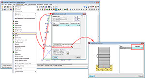
Dimensions and effective mechanical steel areas of slabs for capacity checks of concrete columns and beams
CYPECAD, as of previous versions, takes into account the capacity design criteria of concrete beams and columns, for specific codes when undertaking the seismic analysis of the structure ![]() .
.
The geometric and mechanical properties of the columns and beams are automatically contemplated with the capacity checks (as of previous versions) as are, optionally, the properties of the floor slabs bearing on beams reaching a column (as of the 2014.d version).
To define the geometric and mechanical properties of the floor slabs, with regards to the capacity checks for concrete beams and columns, a new option has been implemented in the program: Assign data for the capacity check (Beam Definition tab > Beams/Walls).
The aforementioned option will only be visible if a seismic analysis is carried out with a design code which has the capacity check implemented for CYPECAD ![]() .
.
When this option is activated, a dialogue box appears where users can define the following data:
- Effective width (1)
- Effective width (2)
- Effective depth (3)
- Mechanical steel area of the top reinforcement
- Mechanical steel area of the bottom reinforcement
Users can assign them freely to any side or end of beams reaching columns. This way, slabs which have different geometric or mechanical properties at either side of the beam, or beams which only have the floor slab on one side can be contemplated.
To identify each of the sides and ends of the beam to which the data has been assigned for the capacity checks, the program displays small magenta triangles at these zones, which are displayed when the option Assign data for capacity check is selected. The triangles will be displayed in green at zones where the properties of the slab have not been assigned, in which case, the dimensions and steel areas of the slab will not intervene in the capacity checks for the concrete beams and columns.
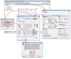
Maximum size and nature of the aggregate
A new option has been implemented whereby users can define a different maximum aggregate size for each type of element: floor slabs, foundations, columns or walls (Job ˃ General data ˃ Aggregate properties in the reinforced concrete section).
Additionally, when the concrete EHE-08 (Spain) or ABNT NBR 6118 Projeto Junho 2013 (Brazil) codes are used, the nature of the aggregate can also be defined, with different values for floor slabs, foundations, columns or walls if users indicate it so. These design codes contain a correction coefficient of the longitudinal deformation module of the concrete, which depends on the nature of the aggregate used for its elaboration.
Using the EHE-08 code, the following aggregate nature types can be selected in accordance with that indicated in Table 39.6 (belonging to the comments of article “39.6. Módulo de deformación longitudinal del hormigón”):
- Cuarcita
- Arenisca
- Caliza normal
- Caliza densa
- Ofita basalto y otras rocas volcánicas - Poroso
- Ofita basalto y otras rocas volcánicas - Normal
- Granito y otras rocas plutonicas
- Diabasas
In the EHE-08 design code, the correction coefficient of the modulus of elasticity of the concrete is contained within the comments of the code, and so it is not obligatory for users to comply with it. When the nature of the aggregate is quartzite (cuarcita), the correction factor of the elasticity modulus has a value of 1, and this would be the option to be used if the reduction factor is not to be applied or, obviously, if this is the real nature of the aggregate that is used.
Using the ABNT NBR 6118 Projeto Junho 2013 code, the following aggregate natures can be selected as indicated in article “8.2.8. Módulo de elasticidade”:
- Basalto
- Diabásio
- Granito
- Gnaisse
- Calcário
- Arenito
Using the ABNT NBR 6118 Projeto Junho 2013 code, when a value of 1 is assigned to the correction coefficient of the modulus of elasticity of the concrete, it belongs to aggregates with “Granito” and “Gnaisse” natures.
Reduction of the concrete resistance of columns
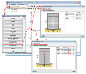
CYPECAD now allows users to apply reduction coefficients to the concrete resistance for each column span that is selected. This is possible with codes which can use the advanced column editor ![]() .
.
These coefficients are defined using the Concrete resistance option (Column Definition tab > Introduction > Columns, shear walls and starts). A column is selected using the left mouse button, after which a dialogue box appears on-screen where users can:
- If the Job general data option is activated, user can:
- View the type and general concrete reduction coefficients of the job
- If the option: Reduce the concrete resistance is activated, users can:
- View the type and general concrete reduction coefficients of the job
- Introduce concrete resistance reduction coefficients for each column span
- Modify the concrete resistance reduction coefficient at the required spans
This allows users to define the design resistance of the concrete for each column span if any tests have been carried out indicating the concrete has a low resistance.
Using the “Copy” option of the “Columns, shear walls and starts” dialogue box (Column Definition tab > Introduction > Columns, shear walls and starts), the program allows for the properties of a selected column to be copied to another that has already been introduced. Amongst the properties that can be copied are the reduction coefficients of the column selected as the model column, if the Concrete resistance option is activated in the dialogue box that appears when the column is selected.
Axial stiffness coefficients for columns, shear walls and walls
In previous versions, users could only introduce one axial stiffness coefficient for all the reinforced concrete columns, shear walls and walls of the job. As of the 2014.d version, three generic axial stiffness coefficients exist which can have different values:
- Axial stiffness coefficient for columns
- Axial stiffness coefficient for shear walls
- Axial stiffness coefficient for walls (reinforced concrete walls and plane stress walls
 )
)
As well as the three generic axial stiffness coefficients, the 2014.d version of CYPECAD also allows for specific axial stiffness coefficients to be assigned to each column, shear wall, reinforced concrete wall or plane stress wall of the job.
An axial stiffness coefficient can be assigned to these elements with a different value at each span, following the process detailed below:
- For columns
The individual axial stiffness coefficients are assigned to each column (Column Definition tab > Introduction > Columns, shear walls and starts > Axial stiffness coefficient > select a column > select “Column properties which differ from the general properties of the job” > Introduce the axial stiffness coefficients for each floor).
- For shear walls
The axial stiffness coefficients for shear walls are assigned to each shear wall type, which implies that all the shear walls of the same type that are introduced will have the axial stiffness coefficients for that type (Column Definition tab > Introduction > Columns, shear walls and starts > Edit > select a shear wall > Define types > select “With different axial stiffness coefficient” > introduce the axial stiffness coefficients for each floor).
- For reinforced concrete walls and plane stress walls
The axial stiffness coefficients for walls are assigned to each wall span that is introduced in a single introduction step (Beam Definition tab > Beams/Walls > Edit > select a wall span > select “With different axial stiffness coefficient” > introduce the axial stiffness coefficients for each floor).
Reduction of reinforcement anchorage and splice lengths in columns, only for bars in tension
As of previous version, the anchorage length of the columns at the last floor and the splice length at other floors could be reduced. Now, with the 2014.d version, users can reduce the length of only bars that are in tension, in which case, a minimum resultant length for bars in tension has been established as Lb (basic anchorage length). This way, the anchorage lengths and splice lengths (if the reduction is also applied to floors below the last floor) will be more uniform.
To implement this new option, the “Reduction of anchorage lengths in columns” dialogue box now contains a new option: “Only for bars in tension”. This option can be activated separately for the last floor and for floors below the last floor.
Advanced beam editor
Improvements in the work environment
Some of the buttons of the toolbar situated at the top of CYPECAD’s advanced beam editor (reinforcement edition, introduce openings, transverse sections), open floating windows that also contain other tools to edit the frames. As of the 2014.d version, these floating windows can be configured, offering the following options:
- Appearance of the floating windows
- Visibility of the floating windows (remain visible or hide automatically)
- Distribution of the tools of the floating windows around the work area
- Memorisation of the position, aspect and visibility of the floating windows
These improvements are the same as those that have been implemented for CYPECAD MEP and are explained in more detail on this webpage ![]() .
.
Dropped rectangular beams with variable sections
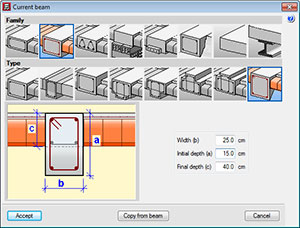
Dropped rectangular beams with variable sections can now be introduced in jobs analysed in accordance with a concrete code or seismic code (if a seismic analysis is being carried out) available for use with the advanced beam editor ![]() .
.
This possibility was already available with Continuous beams program. Now in CYPECAD, within the beam introduction dialogue box, a new type of beam has been added for which the program requests the width, initial depth and final depth.
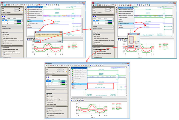
Divide a bar pack (change the layer of some of the bars of a pack)
A new option; Divide, has been implemented in the longitudinal reinforcement edition box of CYPECAD’s advanced beam editor. This option allows users to divide a pack of bars, in such a way that the number of bars indicated by users then becomes part of the other pack. By implementing this option, the one or two packs remaining after the division can be changed to other reinforcement layers.
In previous versions, to change bars belonging to a bar pack from one layer to another, user had to carry out two steps: reduce the number of bars of the packet and create another packet with the same number of bars that were removed (as well as having to indicate the same diameter, position and bar length). This procedure was not only a longer process but also increased the possibility of there being errors in the modifications.
On-screen consultation of the required and effective areas of the reinforcement of a frame
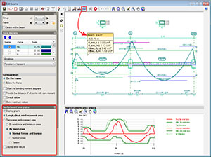
A new option has been implemented: “Consult the required and effective areas” (![]() button) in the advanced beam editor of CYPECAD. When this option is selected, the program displays the required and effective areas of the reinforcement of the frame at the point of the longitudinal section where the cursor is positioned.
button) in the advanced beam editor of CYPECAD. When this option is selected, the program displays the required and effective areas of the reinforcement of the frame at the point of the longitudinal section where the cursor is positioned.
The information displayed moves with the cursor along the frame and displays the corresponding areas at the point where the cursor is positioned.
The data that is visualised on-screen corresponds to the type of reinforcement selected in the “Reinforcement area graphs” section in the left lateral menu of the advanced beam editor (longitudinal reinforcement area, transverse reinforcement area, resistance reinforcement and minimum steel areas...).
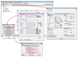
Representation of the floor slab in the transverse sections of beams in the frames drawing
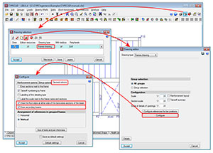
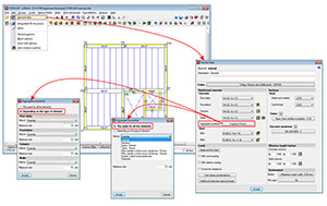
A new option has been included in the 2014.d version of CYPECAD: “Draw the floor slabs at either side of the transverse sections of the beam”. This option is located in the configuration dialogue box for the frames drawing (see image). By activating this option, the floor slab will be displayed in the transverse sections of the frames in the frames drawing.
This option is only available with jobs analysed in accordance with a concrete code or seismic code (if a seismic analysis is being carried out) available for use with the advanced beam editor ![]() .
.
Drawing of secondary beams in the frames drawing
The 2014.d version of CYPECAP includes the option to “Draw secondary beams” in the configuration dialogue box for the frames drawing (see image). This option draws secondary beams (or not draw them if left inactivated) in the longitudinal section of the frames represented in the frames drawings. For CYPECAD, a secondary beam is that which divides which the longitudinal reinforcement of the beam.
This option will only be available with jobs analysed in accordance with a concrete code or seismic code (if a seismic analysis is being carried out) available for use with the advanced beam editor ![]() .
.
Strut3D
Implementation, in Strut3D, of the following concrete codes: ABNT NBR 6118 2007 (Brazil), ABNT NBR 6118 Projeto Junho 2013 (Brazil) and Eurocode 2 (EU, France and Portugal)
The tool, Strut3D, was implemented in the 2013.e version. This tool allows users (in CYPECAD and Metal 3D – using the Pile caps module – and in Foundation elements) to check pile caps using a general analysis methodology whereby the D regions of the reinforced concrete are analysed using a strut and tie method. This tool was only available for use with the Spanish EHE-08 concrete code.
In the 2014.b version, more codes could be used with Strut3D: ACI 318M-08 (USA), Nch430.Of2008 (Chile), NTE E.060:2009 (Peru) and NSR-10 (Columbia).
With the 2014.d version, Stut3D has been implemented to be used with more concrete codes:
- ABNT NBR 6118 2007 (Brazil)
Projeto de estruturas de concreto – Procedimento
- ABNT NBR 6118 Projeto Junho
Projeto de estructuras de concreto – Procedimento (project code that will substitute the code that is currently in force; ABNT NBR 6118 2007)
- Eurocode 2 (EU)
Design of concrete structures. EN 1992-1-1:2004/AC 2008
- Eurocode 2 (France)
Calcul des structures en béton. NF EN 1992-1-1:2005/NA: Mars 2007
- Eurocode 2 (Portugal)
Projecto de estruturas de betão. NP EN 1992-1-1:2010/NA
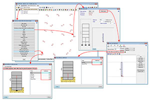
Pile displacements
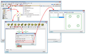
A new option, “Displacement of the piles” has been implemented in the “Piles” dialogue box (see image). This option allows users to introduce a displacement value for each pile of the pile cap with respect to its original position. The displacement is introduced using the X and Y components of the local axes of the pile cap.
This option has been implemented so a change in the position of the piles during the execution phase of the job can be contemplated. If this occurs, the designer can introduce the displacement the piles have undergone with respect to those of the project, and by selecting the check option, can check whether or not the pile cap continues to meet its requirements.
Therefore, the effect of the displacements of the piles that are introduced using this option, are only used to check the pile cap. The design and drawings that are generated are all carried out bearing in mind the original position of the piles.
CYPECAD MEP
Improvements in the work environment of CYPECAD MEP
Floating tool windows and their tools
The improvements in the work environment of CYPECAD MEP of the 2014.d version are related with the use of the floating windows that appear with many of the buttons of the top toolbar, and with the possibility to distribute the tools that contain the floating windows around the working area.
The configuration of these windows and tools is independent for each tab of CYPECAD MEP (Acoustics, Air conditioning, Fire (FDS)...), and so the work in each tab can be adapted to the requirements and habits of each user. For example, if a user usually introduces the construction elements in the Thermal analysis tab, the tools can be distributed in the left lateral side of the work window so that they will always be available in that window and will not appear in other tabs, in which different tools can be included.
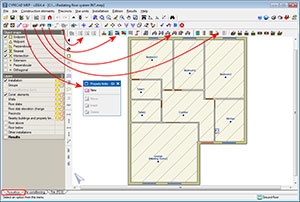
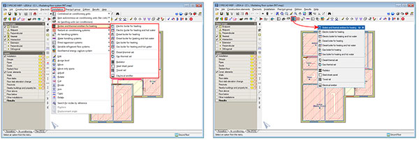
In previous versions, the floating windows appeared on-screen when they were sought from the drop-down menus or when the buttons that appear on the top toolbar where selected. Now, the floating windows only appear when the buttons in the toolbar are selected, whilst the drop-down menus display the different tools in successive drop-down menus by simply placing the mouse cursor on the required option. This way, users can see all the available tools of each drop-down menu, select the required menu and pass the mouse cursor across each option or across other menus. Previously, in order to see the tools of each option, it first had to be selected and then select another option to locate more tools.
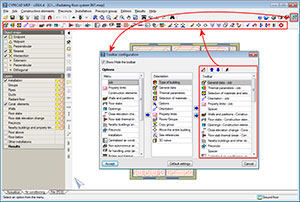 The buttons of the top toolbar are configured using the
 ![]() button, located in the top right of the program window.
button, located in the top right of the program window.
The new configuration possibilities of the floating windows and of the tools they contain are detailed below:
- Appearance of the floating windows
- Visibility of the floating windows (keep visible or hide automatically)
- Distribution of the tools of the floating windows along the sides of the display
- Memorisation of the position, appearance and visibility of the floating windows
Appearance of the floating windows
As of the 2014.d version, the floating windows in CYPECAD MEP can be viewed in three different ways, depending on the distribution of the tools they contain (in previous versions only two types of view modes existed):
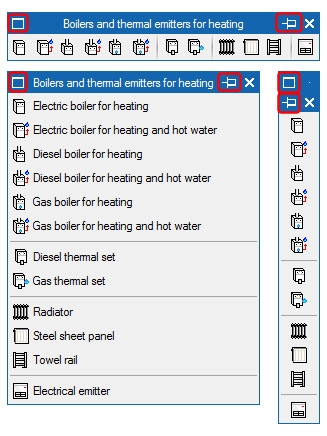
- Tools distributed in a row (without text)
- Tools distributed in a column (with text)
- Tools distributed in a column (without texts) (new view mode of the 2014.d version)
To change the appearance of the floating windows, simply press the ![]() button (situated in the top left hand corner of each window) successively.
button (situated in the top left hand corner of each window) successively.
Visibility of the floating windows (keep visible or hide automatically)
As of the 2014.d version, CYPECAD MEP allows for floating windows to remain visible even if users select other tools of the same tab. This way several floating windows will be accessible at the same time.
For a floating window to remain visible, simply press the ![]() button located in the top right-hand corner. By pressing this button successively, the visibility status of the window changes:
button located in the top right-hand corner. By pressing this button successively, the visibility status of the window changes:
-
 If the button has this appearance, the window remains on screen if even if other tools are selected
  If the button has this appearance, the window will automatically hide when another tool is selected.
There is another way for the tools of the floating windows to always be accessible. This consists in removing them from the windows and distributing them around the working area ![]() .
.
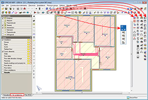
Distribution of the tools of the floating windows along the sides of the display
The tools contained by the floating windows can be positioned around the working area of CYPECAD MEP.
To do so, simply move a floating window to the side, above or below the work area as is shown in the image. The floating windows can be moved on screen like any Windows dialogue box (by constantly pressing the left mouse button whilst it is being displaced).
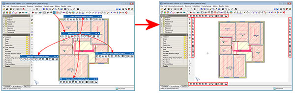
When users begin to move the floating window, the cursor changes appearance and displays an open hand![]() , and when it reaches the side of the work area where the tools of the floating windows can be placed, the cursor changes and displays a pointing hand
, and when it reaches the side of the work area where the tools of the floating windows can be placed, the cursor changes and displays a pointing hand ![]() . At that moment, if the left mouse button is released, the floating window will disappear and its tools will remain positioned on the edge of the work area which the window was displaced to.
. At that moment, if the left mouse button is released, the floating window will disappear and its tools will remain positioned on the edge of the work area which the window was displaced to.
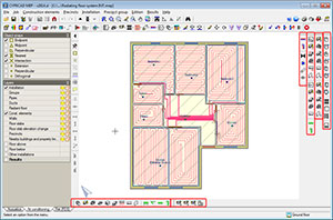
The tools of several floating windows can be placed along the edge, and can be placed alongside one another or below one another. Each tool column or line has a space with a greater width at its start than those separating each tool.
The tools placed in this order are memorised by the program. This way, users can configure the work window of each tab (Acoustics, Air conditioning, Fire (FDS)...) with the tools they usually use.
If users wish to, they can place the tools within their original floating windows. To do so, simply drag the tools placed on the edge toward the inside of the work area, constantly pressing the left mouse button on the spacer at the start of each tool column or line.
Memorisation of the position, appearance and visibility of the floating windows
In previous versions the floating windows did not appear on-screen at the same positions as users had left them last time the program was used. As of the 2014.d version, the program records the position, appearance and visibility of the floating windows, and the distribution of the tools around the work area. This way, when users enter the program or change tab (Acoustics, Air conditioning, Fire (FDS)...), the tool configuration of the floating windows is the same as last time the program was used.
Thermal analysis for France
Improvements and updates have been implemented in the Thermique tab of CYPECAD MEP for France related with technical regulations: RT 2005, RT Existant and RT 2012.
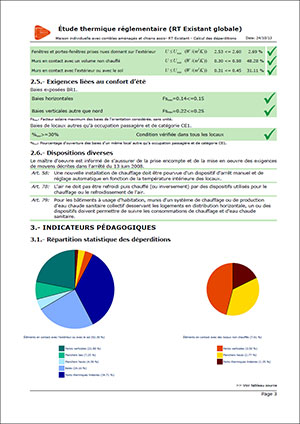
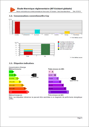
RT 2005 and RT Existant
The Étude thermique RT 2005 and RT Existant reports have been improved; graphs have been added, which represent the percentage loss due to the construction elements and the energy consumptions of the building.
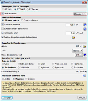
RT 2012
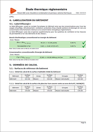
As of the 2014.d version, users can verify, in the analysis of the RT 2012, whether or not the requirements of the Effinergie tag are met ![]() . This check is carried out in the Étude thermique réglementaire RT 2012 report.
. This check is carried out in the Étude thermique réglementaire RT 2012 report.
Furthermore, as of this version, electric and gas double service thermodynamic generators, for heating and sanitary hot water production can be introduced.
The XML file of the RT 2012: Fiche Standardisée RT 2012, 1163_V1.7., has also been updated.
Thermal analysis for Italy
Selection of heating or sanitary hot water systems with several generators acting in series
The 2014.d includes the possibility to select heating, sanitary hot water or mixed systems with several generators acting in series.
Within the “Definizione dei sistemi” dialogue box (Studio termico tab > Dati generali > edit or add in the Sistemi collettivi section) users can introduce systems with several generators working in series. These systems can also be used autonomously for a zone of the building. To do so, zones must be defined in the building (Zone menu) and assign the system to the desired zone in the “Sistemi autonomi” section.
Selection of heating or sanitary hot water systems with several accumulators (generators in series with a shared accumulator or generators with an independent accumulator)
The 2014.d includes the possibility to select heating, sanitary hot water or mixed systems with several accumulators (generators in series with a shared accumulator or generators with an independent accumulator).
Within the “Definizione dei sistemi” dialogue box (Studio termico tab > Dati generali > edit or add in the Sistemi collettivi section) users can introduce systems with several accumulators (generators in series with shared accumulator or generators with an independent accumulator). These systems can also be used autonomously for a zone of the building. To do so, zones must be defined in the building (Zone menu) and assign the system to the desired zone in the “Sistemi autonomi” section.
Using the edit button in the “Accumulo” section of the “Definizione dei sistemi” dialogue box, the data of the selected system can be defined.
Selection of heating or sanitary hot water systems with a heat pump to carry out the thermal analysis
The 2014.d version includes the possibility to select heating, sanitary hot water or mixed systems with a heat pump; so that the primary energy demand and efficiency of the heating systems of the building are taken into account in the analysis. This analysis is carried out in accordance with the UNI/TS 11300-4 code (Utilizzo di energie rinnovabili e di altri metodi di generazione per la climatizzazione invernale e per la produzione di acqua calda sanitaria).
Users can select a type of pump in the “Generazione” section of the “Definizione dei sistemi” dialogue box (Studio termico tab > Dati generali > edit or add in the Sistemi collettivi section). These systems can also be individual and for this, zones have to be defined in the building (Zone menu) and assign the system to a zone in the “Sistemi autonomi” section.
Using the edit button in the “Generazione” section of the “Definizione dei sistemi” dialogue box, the data of the selected system can be defined.
Within reports: “Fabbisogni di energia primaria e rendimenti per la climatizzazione invernale del sistema edificio-impianto” and “Fabbisogno di energia primaria e rendimenti per la produzione di acqua calda sanitaria” (Studio termico > File > Stampare > Relazioni del progetto) the results can be consulted.
Selection of heating systems with cogeneration to carry out the thermal analysis
The 2014.d version includes the possibility to select heating and sanitary hot water systems using cogenerators; so that the primary energy demand and efficiency of the heating systems of the building are taken into account in the analysis. This analysis is carried out in accordance with the UNI/TS 11300-4 code (Utilizzo di energie rinnovabili e di altri metodi di generazione per la climatizzazione invernale e per la produzione di acqua calda sanitaria).
Users can select a type of cogenerator in the “Generazione” section of the “Definizione dei sistemi” dialogue box (Studio termico tab > Dati generali > edit or add in the Sistemi collettivi section). These systems can also be individual and for this, zones have to be defined in the building (Zone menu) and assign the system to a zone in the “Sistemi autonomi” section.
Using the edit button in the “Generazione” section of the “Definizione dei sistemi” dialogue box, the data of the selected heating system can be defined.
Within the report: “Fabbisogni di energia primaria e rendimenti per la climatizzazione invernale del sistema edificio-impianto” (Studio termico > File > Stampare > Relazioni del progetto) the results can be consulted.
Selection of auxiliary heating or sanitary hot water generation systems using solar thermal collectors to carry out the thermal analysis
The 2014.d version includes the possibility to select auxiliary generation systems for heating, sanitary hot water or mixed systems using solar thermal collectors; so that the primary energy demand and efficiency of the heating systems of the building are taken into account in the analysis. This analysis is carried out in accordance with the UNI/TS 11300-4 code (Utilizzo di energie rinnovabili e di altri metodi di generazione per la climatizzazione invernale e per la produzione di acqua calda sanitaria).
Users can select a type of cogenerator in the “Generazione” section of the “Definizione dei sistemicuadro” dialogue box of the “Definizione dei sistemi” dialogue box (Studio termico tab > Dati generali > edit or add in the Sistemi collettivi section). These systems can also be individual and for this, zones have to be defined in the building (Zone menu) and assign the system to a zone in the “Sistemi autonomi” section.
Using the edit button n the “Generazione” section of the “Definizione dei sistemi” dialogue box, the data of the selected heating system can be defined.
Within reports: “Fabbisogni di energia primaria e rendimenti per la climatizzazione invernale del sistema edificio-impianto” and “Fabbisogno di energia primaria e rendimenti per la produzione di acqua calda sanitaria” (Studio termico > File > Stampare > Relazioni del progetto) the results can be consulted.
Selection of photovoltaic collectors to carry out the thermal analysis
The 2014.d version includes the possibility to select photovoltaic collectors so that the primary energy demand is taken into account in the analysis. This analysis is carried out in accordance with the UNI/TS 11300-4 code (Utilizzo di energie rinnovabili e di altri metodi di generazione per la climatizzazione invernale e per la produzione di acqua calda sanitaria).
Users can select the photovoltaic collectors in the “Generazione” section of the “Definizione dei sistemi” dialogue box (Studio termico tab > Dati generali > edit or add in the Sistemi collettivi section). These systems can also be individual and for this, zones have to be defined in the building (Zone menu) and assign the system to a zone in the “Sistemi autonomi” section.
Air conditioning
“ASHRAE Weather Data Viewer 4.0” climate database
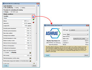
The “Weather Data Viewer 4.0” of the American Society of Heating, Refrigerating and Air-conditioning Engineers (ASHRAE) has been incorporated in the 2014.d version. Using this database, users can select any of the 5,564 stations located around the world to import the weather data required for the air conditioning design.
To access this base, click on “General data (Air conditioning)” (Air conditioning tab > Job > General data) and click on the ![]() (ASHRAE Weather Data Viewer 4.0) button in the “Climatic conditions” section. Using the selection menu, users can choose amongst any of the 5,564 locations to import the data and work with them.
(ASHRAE Weather Data Viewer 4.0) button in the “Climatic conditions” section. Using the selection menu, users can choose amongst any of the 5,564 locations to import the data and work with them.
Radiant floor. Automatic and manual selection of the most unfavourable circuit
With the 2014.d version, important improvements have been introduced in the analysis and edition of the radiant floors which provide more adjusted results and greater control on behalf of users.
In this sense, the automatic selection of the most unfavourable circuit of each manifold has been optimised, which is what will establish the impulse temperature calculation. Now, the automatic selection of the radiant floor carried out by the program, not only takes into account the load required by each circuit (as was done in previous versions), but also takes into account the specific properties of each circuit.
Furthermore, in the 2014.d version the possibility has been implemented for users to determine, in accordance with their criteria, which is the most unfavourable circuit, that will establish the calculation of the impulse temperatures. This way, users can have greater control on the design of the installation. The selection of the most unfavourable circuit is carried out when the circuit is edited.
In both cases (automatic selection and manual selection) the program indicates, in the analysis report, which circuit has been used to calculate the impulse temperature of the manifold; the value of its thermal fluid density is displayed in bold text in the circuit design section.
Radiant floor. Optimisation of the analysis of the power provided by each circuit
The calculation of the real power provided by each circuit has been optimised. Furthermore, this data is now included in the analysis reports. This way, the power which theoretically should be covered by a circuit can be seen (required power – which is used to design the circuit) and the real power that it is providing due to the design conditions that have finally been selected (installed power).
 Electricity (Brazil, Spain and Portugal)
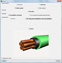
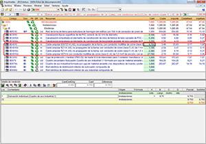
Improvements in the selection of the supply cable
The cable selection in the electricity program has been restructured. The new panel facilitates the selection of the cable that supplies the different nodes that are introduced in the program.
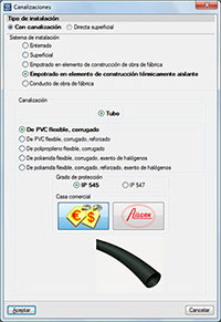 Improvements in the selection of the type of installation (Channelled or Direct surface)
The selection of the type of installation when the different electric channels are introduced has been restructured. The new panel facilitates the selection of the installation system as well as the material used in it.
Bill of quantities of the installation
Two different job units appear in the bill of quantities of the electric installation generated by the program:
- IEH010 (corresponding to the cables)
- IEO010 (corresponding to the channels)
Arquimedes
Import quantities from ArchiCAD 17 (64-bit)
The 2014.d version of Arquimedes has been updated to adapt the quantities imported from ArchiCAD’s new version “ArchiCAD 17 (64-bit)”.
Return to the 2014 version download area
Tel. USA (+1) 202 569 8902 // UK (+44) 20 3608 1448 // Spain (+34) 965 922 550 - Fax (+34) 965 124 950