
New features and download of the 2013.k version
(22 March 2013)
![]()
- New modules and programs
- Code implementations and improvements in its application
- Loads on structures. Seismic loads
- Thermal insulation
- RT Existant (France)
- UNI/TS 11300-1, UNI 10349 (Italy), UNI 10351 (Italy), EN ISO 13786 (EU)
- EN ISO 6946, EN ISO 13370, EN ISO 13790:2008, EN ISO 13789, EN ISO 14683, EN ISO 10211
- Acoustic insulation
- Electricity
- New features in CYPECAD
- Advanced beam editor of CYPECAD
- Advanced column editor of CYPECAD
- Post-tensioned concrete slabs
- Capacity design criteria for seismic design of concrete columns and beams with the 1997 UBC (USA) code
- New features in Metal 3D
- Punching shear verification
- New features in CYPECAD MEP
- New features in Arquimedes and Job Control
- Return to the 2013 version download area
New modules and programs
Geothermal energy harvesting systems (Building services)
The 2013.k version arrives with a new module: Geothermal energy harvesting systems, integrated in the Air Conditioning tab of CYPECAD MEP. This new module has been conceived to design geothermal energy harvesting systems.
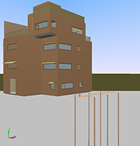
Geothermal heat pump systems are geothermal systems with low enthalpy which use a heat pump and an energy harvesting system in the ground to utilise the temperature of the ground. The key aspect of the efficiency of this type of system lies in the utilisation of the energy that is accumulated in the ground in a constant and stable manner, in such a way that the electrical energy consumed by the system is less than that which is consumed by a conventional heat pump system.
Once users select a geothermal heat pump (Air Conditioning tab > Installation > Centralised air conditioning units) and define the energy requirements to be covered by the pump (results of which can be obtained using the Export to energy plusTM and Calculation of summer and winter thermal loads modules), the program can then design the geothermal heat exchanger that would be required for the installation to operate correctly.
The design of the geothermal exchanger is based on the proposed design procedure contained in the manual of the American Society of Heating, Refrigerating and Air-Conditioning Engineers (ASHRAE) “Ground-Source Heat Pumps: Design of Geothermal Systems for Commercial and Institutional Buildings”.
More information on this new CYPECAD MEP module is available here: Geothermal energy harvesting systems.
CYPECAD MEP for Italy (Building services)
As of the 2013.k version, CYPECAD MEP is available in Italian. CYPECAD MEP for Italy includes the following tabs: Studio termico, Acustica, Climatizzazione and Incendio (FDS).
More information on this implementation will be available shortly on the Italian webpage of CYPE.
Code implementations and improvements in its application
Loads on structures. Seismic loads
1997 UBC (USA)
Uniform Building Code.
This seismic load was already implemented in CYPECAD and Metal 3D as of previous versions. As of the 2013.k version, if users select the 1997 UBC (USA) code and combine it with any of the concrete codes CYPECAD allows to be used with the Advanced beam editor, the editor may also be used.
Additionally, the U.L.S. reports for columns and beams that are generated by their advanced editors, include the capacity design criteria for bending and shear for the seismic design of concrete supports, and capacity design criteria for shear for the seismic design of concrete beams.
Thermal insulation
RT Existant (France)
Réglamentation Thermique RT Existant.
Implemented in the new module: RT Existant par element et globale Th-C-E ex, integrated in the “Étude climatique” tab of CYPECAD MEP (installed in French and if the country selected in the job is France).
More information on this new CYPECAD module can be found in the French webpage of CYPE.
UNI/TS 11300-1, UNI 10349 (Italy), UNI 10351 (Italy), EN ISO 13786 (EU)
- UNI/TS 11300-1 (Italy)
Prestazioni energetiche degli edifici – Parte 1: Determinazione del fabbisogno di energia termica dell’edificio per la climatizzazione estiva ed invernale.
- UNI 10349 (Italy)
Riscaldamento e raffrescamento degli edifici – Dati climatici.
- UNI 10351 (Italy)
Materiali da costruzione – Conduttività termica e permeabilità di calcolo e permeabilità al vapore.
- EN ISO 13786 (EU)
Thermal performance of building components. Dynamic thermal characteristics. Calculation methods.
These codes have been implemented in the module: Verifica dell’isolamento termico conformemente alla UNI 11300-1, integrated in the “Studio termico” tab of CYPECAD MEP (installed in Italian and if the country selected in the job is Italy).
EN ISO 6946, EN ISO 13370, EN ISO 13790:2008, EN ISO 13786, EN ISO 14683, EN ISO 10211
- EN ISO 6946 (EU)
Building components and building elements. Thermal resistance and thermal transmittance. Calculation method
- EN ISO 13370 (EU)
Thermal performance of buildings. Heat transfer via the ground. Calculation methods
- EN ISO 13790:2008 (EU)
Energy performance of buildings. Calculation of energy use for space heating and cooling
- EN ISO 13789 (EU)
Thermal performance of buildings. Transmission and ventilation heat transfer coefficients. Calculation method
- EN ISO 14683 (EU)
Thermal bridges in building construction. Linear thermal transmittance. Simplified methods and default values
- EN ISO 10211 (EU)
Thermal bridges in building construction. Heat flows and surface temperatures.
These codes were already implemented in the modules corresponding to the thermal study of those countries for which CYPECAD MEP has been implemented. Now, in the 2013.k version, a new module has been implemented: Verifica dell’isolamento termico conformemente alla UNI 11300-1, integrated in the “Studio termico” tab of CYPECAD MEP for Italy.
Acoustic insulation
DPCM 5/12/1997 (Italy)
Determinazione dei requisiti acustici passivi degli edifici.
This code has been implemented in the module: Verifica dell’isolamento acustico conformemente al DPCM 5/12/1997, integrated in the “Acustica” tab of CYPECAD MEP (installed in Italian and if the country selected in the job is Italy).
Electricity
ABNT NBR 5410:2004 (Brazil)
Norma Brasileira ABNT NBR 5410 (2004). Instalações eléctricas de baixa tensão.
Implemented in the Electricidade tab of CYPCAD MEP (installed in Portuguese for Brazil and if the country selected in the job is Brazil).
New features in CYPECAD
Advanced beam editor of CYPECAD
Improved consultation of U.L.S. and S.L.S. checks
In previous versions, the U.L.S. and S.L.S checks dialogue box displayed the complete report of the checks carried out by the program (![]() U.L.S. and S.L.S. checks at the worst case point or
U.L.S. and S.L.S. checks at the worst case point or ![]() U.L.S. and S.L.S. checks at a point buttons of the Advanced beam editor). To identify the failed checks or consult a specific check, users had to run through the entire report.
U.L.S. and S.L.S. checks at a point buttons of the Advanced beam editor). To identify the failed checks or consult a specific check, users had to run through the entire report.
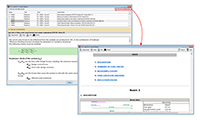
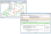
Now, as of the 2013.k version, a detailed check and specific check have been implemented in the dialogue box, for each U.L.S. and S.L.S. check, which helps to speed up the verification procedure. These checks can be found in the U.L.S. and S.L.S. checks dialogue box; within the top-half is a list of the checks that have been carried out (indicating whether or not these fail). Users select the check to be consulted, which is then displayed in more detail in the bottom-half of the screen:
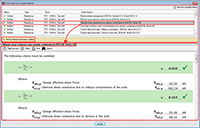
The checks that have been carried out are displayed in a table containing the following columns:
- Status
Displays a green tick with the word Verified, or a red cross with Not verified.
- Type
Indicates the type of check (resistance, cracking, deflection...).
If the checks that have been carried out are of the same type, the “Type” column will not appear. This may occur in the case of a frame with steel spans for which only the surrounding temperature resistance has been checked, without checking for fire resistance or deflection limits.
- Zone
Indicates the span interval at which the check has been carried out and the zone of the affected transverse section (top or bottom reinforcement). If the check affects the whole span, then a text will appear indicating the entire span.
If the U.L.S. and S.L.S. checks dialogue box has been viewed using the ![]() button (U.L.S. and S.L.S. checks at a point), the “Zone” column does not appear in the report.
button (U.L.S. and S.L.S. checks at a point), the “Zone” column does not appear in the report.
- Code checks
Includes a description of the check.
 Above the table is a box that users can mark to Only show the failed checks, which will not appear if no checks fail or if all fail.
 Below the table, the program indicates the number of checks that fail (together with a red cross on the left) or a text indicating “All the checks have been verified” (together with a green mark on the left).
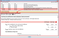
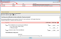
The details of the check selected in the table appear in the bottom-half of the “U.L.S. and S.L.S. checks” dialogue box. This part of the dialogue box is headed with the description of the check selected in the table displaying the checks (the same text that appears in the Code checks column), and is the followed by detailed information on the check. This information can be seen in the preview of the print-out or be printed directly.
The complete U.L.S. and S.L.S. checks report (![]() U.L.S. and S.L.S. checks at the worst case point or
U.L.S. and S.L.S. checks at the worst case point or ![]() U.L.S. and S.L.S. checks at a point buttons, both of the selected span) as was in previous versions in the U.L.S. and S.L.S. checks dialogue box, can now be obtained by selecting the
U.L.S. and S.L.S. checks at a point buttons, both of the selected span) as was in previous versions in the U.L.S. and S.L.S. checks dialogue box, can now be obtained by selecting the ![]() button, situated in the top right-hand corner of this dialogue box.
button, situated in the top right-hand corner of this dialogue box.
These detailed and specific U.L.S. checks have also been implemented in CYPECAD’s advanced column editor, and in the U.L.S. checks dialogue box of Metal 3D or Integrated 3D structures of CYPECAD.
Advanced column editor of CYPECAD
Improved consultation of U.L.S. checks
As of previous versions, CYPECAD provided U.L.S. reports for concrete columns using its advanced column editor, which displayed all the checks carried out during the design process (Results > Columns > Edit > select column > select ![]() symbol from the “Summary of code checks” table – to generate the U.L.S. checks report of the selected column span -, or click on the
symbol from the “Summary of code checks” table – to generate the U.L.S. checks report of the selected column span -, or click on the ![]() button – to generate the U.L.S. checks report of the worst case span for each check).
button – to generate the U.L.S. checks report of the worst case span for each check).
To identify the failed checks or consult a specific check, users had to run through the entire report.
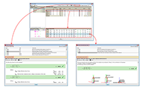
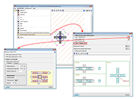
Now, as of the 2013.k version, a detailed check and specific check have been implemented in CYPECAD’s advanced column editor, for each U.L.S. check, which helps to speed up the verification procedure. As has been done with the U.L.S. and S.L.S. checks reports for concrete beams, when users select any of the options to consult the U.L.S. checks of the concrete columns ( ![]() symbol or
symbol or ![]() button), a dialogue box appears, displaying a list of the checks that have been carried out in the top-half of the box. Users select the check to be consulted, which is then displayed in more detail in the bottom-half of the screen.
button), a dialogue box appears, displaying a list of the checks that have been carried out in the top-half of the box. Users select the check to be consulted, which is then displayed in more detail in the bottom-half of the screen.
This dialogue box has the same properties as the dialogue box that appears when using the concrete beam editor, explained in detail, in the previous section of this webpage (Advanced beam editor of CYPECAD)
Post-tensioned concrete slabs
Distance between the tendons and the top surface at intermediate supports
The distance between the tendons and the top surface at intermediate supports (their least top cover) is defined as generic data for the job in the Options dialogue box (Beam Definition tab > Post-tensioned > Options), together with the other parameters to be introduced to define the layout of the tendons.
Different parameters can be defined for the tendons when these are being introduced (Beam Definition tab > Post-tensioned > Introduce concentrated tendons or Introduce distributed tendons) or when editing a specific tendon (Beam Definition tab > Post-tensioned > Edit a tendon). Users can select two options in the Layout section of the dialogue boxes that appear when introducing or editing tendons:
- General job parameters
This option informs users of the parameters that have been defined in the Options dialogue box. By selecting it, the general job parameters can be assigned to the introduced or edited tendons.
- Particular tendon parameters
This option opens a dialogue box where the layout parameters of the tendons that are being introduced or edited can be defined. By selecting it, the specific parameters are assigned to those tendons. The previous versions contained the option to define the Distance between the tendons and the top surface at intermediate supports. In the 2013.k version, this parameter has disappeared from the dialogue boxes which assign specific parameters and, now, the smallest top cover is defined when introducing the flexure lines of the tendons. The general cover for the whole job is still defined in the Options dialogue box (Beam Definition tab > Post-tensioned > Options).
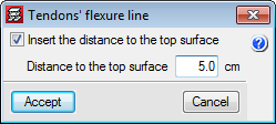
In the new 2013.k version, when a flexure line is introduced, a dialogue box appears in which users can activate the option to Insert the distance to the top surface and define its numerical value for the flexure line that is being introduced. The tendons that cross this flexure line will adopt this value as their minimum top cover at that point. If the option to “Insert the distance to the top surface” has not been activated, the value of the cover will be that which has been defined in the Options dialogue box (Beam Definition tab > Post-tensioned > Options) in the parameter: Distance to the top surface in the intermediate supports.
Bearing in mind the introduction of the flexure lines now includes this possibility, two new options have been implemented in the “Pot-tensioned” dialogue box (Beam Definition tab > Post-tensioned), which allow for a flexure line, which has already been introduced, to be edited (Edit flexure lines of the tendons) or assign a selected flexure line to others that are selected individually or using a capture window (Assign flexure lines of the tendons).
By having the distance between the tendons and the top surface at intermediate supports as an option in the flexure lines box, different top covers can be defined for the same tendon in a more rapid and intuitive manner, which is useful for cantilevers or slabs with varying depths.
Representation of the deviation loads when editing the tendons
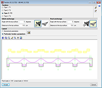
The 2013.k version includes the representation of the deviation loads of a tendon in the longitudinal section that appears in its edition dialogue box (Beam Definition tab > Post-tensioned > Edit a tendon).
Capacity design criteria for seismic design of concrete columns and beams with the 1997 UBC (USA) code
The 2013.e, 2013.g, 2013.h, 2013.i and 2013.j versions of CYPECAD implemented the capacity design criteria for bending and shear for the seismic design of concrete supports, and capacity design criteria for shear for the seismic design of concrete beams in accordance with the following codes: ACI 318M-08 (USA – International), EHE-08 (Spain), NCSE-02 (Spain), NSR10 (Colombia) and IS 13920:1993 (India).
Now, implemented for the 2013.k version, are the capacity design criteria for bending and shear for the seismic design of concrete supports, and capacity design criteria for shear for the seismic design of concrete beams in accordance with the 1997 UBC (USA) code.
New features in Metal 3D
U.L.S. checks
Improved consultation of U.L.S. checks
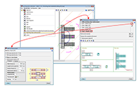
As of previous versions Metal 3D and the integrated 3D structures of CYPECAD generate detailed ultimate limit state check reports for steel (rolled, welded and cold-formed), aluminium and timber bars (Analysis > U.L.S. checks > select a bar). To identify the checks that fail or consult a specific check, users must run through the entire report.
Now, as of the 2013.k version (as has been done for columns and beams in CYPECAD), “Metal 3D” and “Integrated 3D structures of CYPECAD” include a detailed check and specific check for each U.L.S. check, which helps to speed up the verification procedure.
The top-half of the dialogue box that appears when users select the U.L.S. checks option from the Analysis menu, displays a table containing a list of all the checks that have been carried out. Users select the check to be consulted, which is then displayed in more detail in the bottom-half of the screen.
This dialogue box has the same properties as the dialogue box that appears when using the concrete beam editor, explained in detail, in the section on the Advanced beam editor of CYPECAD of this webpage.
Punching shear verification
Punching shear reinforcement using beams
The 2013.k version of Punching shear verification allows users to provide reinforcement using beams. Now, the Types of reinforcement dialogue box (General data > Punching shear reinforcement > Edit or create a type of reinforcement) includes the possibility to select a Beam or Crossed beams as well as reinforcement at 45º. Several beams can be included in one or both directions (appropriate for punching shear reinforcement in the case of very wide columns).
New features in CYPECAD MEP
Geothermal energy harvesting systems in the Air Conditioning tab
The 2013.k version arrives with a new module: Geothermal energy harvesting systems, integrated in the Air Conditioning tab of CYPECAD MEP. This new module has been conceived to design geothermal energy harvesting systems.
More information on this new module of CYPECAD MEP can be found in the New modules and programs section of this webpage.
CYPECAD MEP for Italy
As of the 2013.k version, CYPECAD MEP is available in Italian. CYPECAD MEP for Italy includes the following tabs: Studio termico, Acustica, Climatizzazione and Incendio (FDS).
More information on this implementation will be available shortly on the Italian webpage of CYPE.
Export to IFC format from CYPECAD MEP
Improved export of air ducts
The export of air ducts to IFC format has been improved. The improvements consist of the assignment of colours and materials, as well as their corresponding descriptive texts.
Specific entities for the connections of the ducts are also included. These elements are generated by the program and, therefore, are only exported to IFC format if the installation has been analysed.
Improved export of boilers and emitters for heating
The export of boilers and emitters for heating: Electric boilers for heating, Electric boilers for heating and SHW, Gasoil boilers for heating and SHW, Gas boilers for heating, Gas boilers for heating and SHW, Gasoil thermal sets, Gas thermal sets, Biomass boilers, Radiators, Steel plate panels, Towel rails and Electrical emitters.
All these elements were already exported to IFC format (Industrial Foundation Classes) as of previous versions. Now, with the 2013.k version, the materials and colours are assigned appropriately in accordance with the IFC entity.
New features in Arquimedes and Job Control
Import from CSV format
The tool used to import concepts in CSV format to Arquimedes has been improved (Decomposition tree menu > Tree > Import from CSV format). In previous versions, this option was called “Import decomposition from CSV format” and allowed for a CSV file to be imported to be added as the decomposition of a chapter.
As of the 2013.k version, this option is now called Import from CSV format and allows for information to be imported from:
- CSV format files
- The clipboard of the operating system, where the user has copied information from Excel spreadsheets
The option, Import from CSV format, has also been included in the contextual menu that appears when users click, using the right mouse button, on a “Chapter” or “Job item” type concept (with or without decomposition) in the “Decomposition tree” window of Arquimedes.
Additionally, the program offers several import possibilities, depending on the concept that has been selected in the Decomposition tree window of Arquimedes. These possibilities are displayed in a dialogue box before importing, when the option to Import from CSV format is selected. These are:
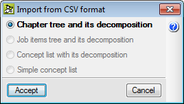
- Chapter tree and its decomposition
This option must be used when the information to be imported contains one or more chapter levels, including job items with their decomposition and, optionally, their quantity details. For the information to be extracted appropriately, each decomposed element, be it a chapter or job item, must have a line referred to as the “decomposition footer” that indicates which is the last element of its decomposition, and so be able to interpret the nested decompositions correctly. The files produced when the jobs are exported to Excel belong to this type of format.
This option can be activated in the “Import from CSV format” dialogue box if the concept that has been selected previously is of the “Chapter” type (including the root chapter).
- Job items tree and its decomposition
This type of import should be used when the information to be imported only contains job items with their corresponding decompositions and details. This format is a subgroup of the previous format, and so the same rules are applicable concerning the “decomposition footer”.
As in the previous option, it is only active when the selected concept is of the “Chapter” type.
- Concept list with its decomposition
The information imported using this option requires a more simple format. A “decomposition footer” is not required. In this case, the different column arrangement is used to distinguish the decomposed concepts (do not have a price or amount) from the unit items they are composed of (contain quantity and price).
It is active with the “Chapter” and “Job item” concept types.
- Simple concept list
The information imported using this option requires the most simple format. It consists of a list of concepts that may or may not contain a quantity or yield, which will be added to the decomposition of the current concept.
It is active with the “Chapter” and “Job item” concept types.
Once the option has been chosen, the program opens another dialogue box to edit the data import process.
Executed quantity and Executed amount columns with data at job unit level
The ExecQuant and ExecPrice columns contain new data at unit price level.
- ExecQuant
The yield can be obtained, at unit price level, based on the direct charges to job items and on the charge repercussions to chapters. Now, the yield can be obtained of the execution of a unit of a corresponding job item (by adding all the supplied quantities charged to a job item and dividing by the executed quantity of the job item).
- ExecPrice
At unit level, the price of the supply is displayed in the charge, or if there is no charge, the probable price in the ProbablePrice column. This way, the price of the root chapter will reflect the foreseen cost at the end of the job as a result of the current execution and the weighted average price of all the supplies that have been contracted of that concept by the cost centre, if it has been contracted, or otherwise, the foreseen price (price in the reference budget of the job control).
Improvements in concept duplication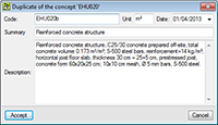
A new option has been implemented for when users wish to obtain a new concept as a duplicate of another existing concept: Paste duplicate, included in the contextual menu that appears by right clicking with the mouse button on the original concept. This option appears if the original concept has been copied previously (right click with the mouse button on the concept to be duplicated > Copy).
Once the Paste duplicate option has been selected, the Duplicate of the concept dialogue box appears, where the program proposes a new code for which users can then modify the measurement units, date, summary and description of the original concept. The quantity of the original concept is not copied during the duplication process.
Improvements in concept organisation
To help organise the concepts at the same level, new options have been included in the contextual menu of the “Decomposition tree” window, which are used to move the selected concept upwards or downwards.
More options in contextual menus
Two new options have been implemented in the contextual menu that appears in the “Decomposition tree” window when a concept is selected using the right mouse button: Change unit price to auxiliary item and Change the nature of the concept.
These options simplify the creation process of a bill of quantities or a price database by reusing existing concepts and adapting their nature or changing them to auxiliary prices if necessary. As of previous versions, a job unit with decomposition can be changed to a unit concept using the option Delete the decomposition of the concept.
New report templates
The following report templates have been implemented:
- Multi-language templates:
- Valuation report with indication of the partial certification of each job item
Template file: pl_00229.pla
Type: Certification
Within this template, the certified quantity lines are identified in the job items with their corresponding closed certification.
- Valuation report summary
Template file: pl_00230.pla
Type: Summary certif.
Prints the valuation report summary.
- Templates in Portuguese for Brazil:
- Curva ABC de materiais
Template file: pl_br002.pla
Type: ZG Brasil
- Orçamento – Planilha Mo+Mat 6 colunas
Template file: pl_br004.pla
Type: ZG Brasil
- Orçamento com Quantidades por insumo
Template file: pl_br003.pla
Type: ZG Brasil
- Orçamento de materiais e mão de obra
Template file: pl_br001.pla
Type: ZG Brasil
- Templates in French
- Devis estimatif
Template file: pl_afrf001.pla
Type: ZG Afrique Francophone
Return to the 2013 version download area
Tel. USA (+1) 202 569 8902 // UK (+44) 20 3608 1448 // Spain (+34) 965 922 550 - Fax (+34) 965 124 950