
New features and download of the 2013.c version
(10th August 2012)
![]()
Code implementation and improvements in its application
Code regarding loads on structures. Wind loads
NV 65:2009 (France)
Règles NV 65. Règles définissant les effets de la neige et du vent sur les constructions et annexes.
Implemented in CYPECAD. This code was already implemented in the Portal frame generator.
Code regarding loads on structures. Seismic loads
Norma Técnica E.030 (Peru). Static analysis method and correction due to base shear
Norma Técnica E.030 (Peru). Static analysis method and correction due to base shear.
Peru’s E.030 code (seismic design) was already implemented in previous versions in CYPECAD and Metal 3D for the dynamic analysis method (spectral modal).
For this code, the 2013.c version includes in CYPECAD:
- A static analysis method (equivalent lateral force)
Users can select the analysis method (dynamic or static) using the Analysis method option within the dialogue box in which seismic action is defined. - The correction due to base shear
This correction is applied when the seismic design is carried out using the dynamic analysis method (spectral modal).
Continuous beams
Reinforcement area graphs
Implemented in Continuous beams are graphs representing the required area of the reinforcement and the effective area of the reinforcement provided in a frame.
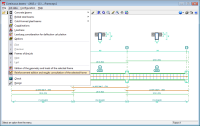
These graphs are represented in the reinforcement edition screen (Job data > Reinforcement edition and results consultation of the selected frame). Displayed in the top part of the screen is the reinforcement of the frame (where the force diagrams can be represented) and in the bottom part are the area graphs.
Users can select the longitudinal reinforcement area representation (top and bottom) or that of the transverse reinforcement area. The area required depending on the resistance and minimum required reinforcement can be represented in each representation (longitudinal or transverse) or just the area required depending on the resistance. The numerical values of the areas can also be viewed. These representation options can be configured in the Reinforcement area graphs section, located in the left side menu of the reinforcement edition screen.
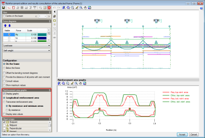
The reinforcement area graphs are of great use for when introducing or modifying the reinforcement. Users can see the areas covered by the reinforcement whilst the introduction or modification is taking place (even deducting its anchorage length).
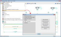
Beam options
The 2013.c version includes more design and check options for concrete beams, and for representation in drawings and takeoff for steel beams. The options of Continuous beams can be edited in Job data > Options. All the available options can be consulted in this dialogue box. The options which have been implemented in the 2013.c version are:
- Design / Code checks
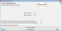
- Assembly reinforcement
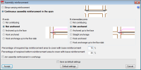
The program considers the following construction arrangements:
- Stirrup-carrying reinforcement
- Continuous assembly reinforcement in the span
- Top reinforcement
- Bottom reinforcement
- Transverse reinforcement
- Stirrup symmetry
- Tie all the longitudinal bars
This option allows for all the longitudinal bars to be tied using crossties even if they are provided in different layers. It is of great use for countries where this is commonly used in their construction methods (France, Morocco or Algeria). - Stirrups of different diameter in a beam
- Multiple stirrup layout
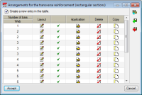
- Stirrup-carrying reinforcement
The transverse reinforcement layout is configured in this section for when stirrup-carrying assembly reinforcement construction layout is used (can be selected in the Assembly reinforcement option). There are different configurations for:
- Rectangular sections
- Rectangular sections with one flange
- Rectangular sections with two flanges
- Assembly reinforcement
- Steel beams
- Length to consider in steel beams
The length to consider for steel beams in beam drawings and in their takeoff is indicated in this section:
- Up to the face of the support element
- Up to the axis of the support element
- Up to the axis in intermediate supports and the external face in end supports
- Length to consider in steel beams
Tel. USA (+1) 202 569 8902 // UK (+44) 20 3608 1448 // Spain (+34) 965 922 550 - Fax (+34) 965 124 950